Page 2010 of 2057

Speed Control
Inspection and Verification
1. Verify the customer concern by operating thesystem.
2. Visually inspect for obvious signs of mechanical or electrical damage.
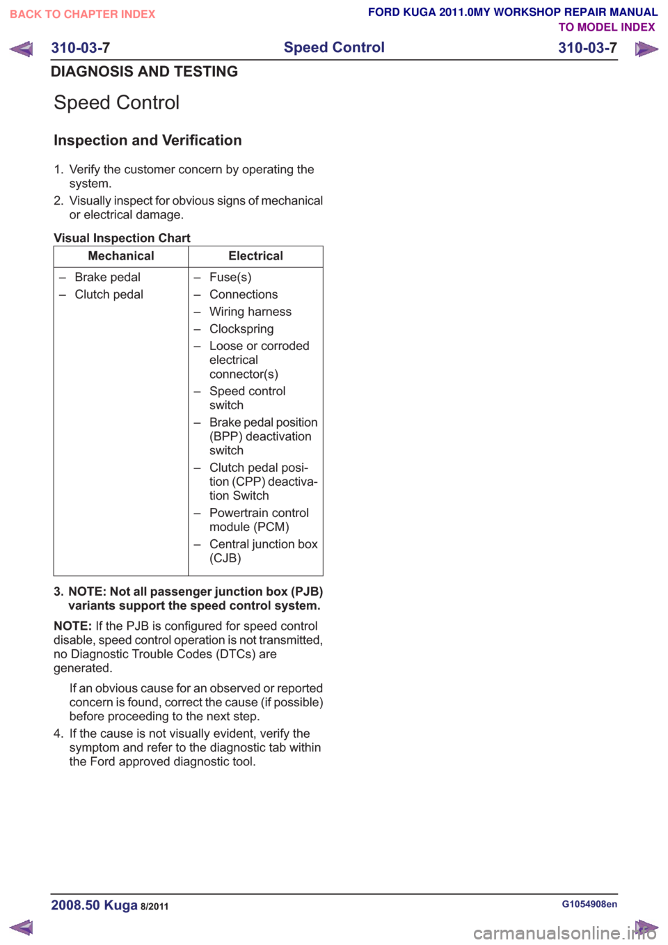
Visual Inspection Chart
Electrical
Mechanical
– Fuse(s)
– Connections
– Wiring harness
– Clockspring
– Loose or corrodedelectrical
connector(s)
– Speed control switch
– Brake pedal position (BPP) deactivation
switch
– Clutch pedal posi- tion (CPP) deactiva-
tion Switch
– Powertrain control module (PCM)
– Central junction box (CJB)
– Brake pedal
– Clutch pedal
3. NOTE: Not all passenger junction box (PJB) variants support the speed control system.
NOTE: If the PJB is configured for speed control
disable, speed control operation is not transmitted,
no Diagnostic Trouble Codes (DTCs) are
generated.
If an obvious cause for an observed or reported
concern is found, correct the cause (if possible)
before proceeding to the next step.
4. If the cause is not visually evident, verify the symptom and refer to the diagnostic tab within
the Ford approved diagnostic tool.
G1054908en2008.50 Kuga8/2011
310-03- 7
Speed Control
310-03- 7
DIAGNOSIS AND TESTING
TO MODEL INDEX
BACK TO CHAPTER INDEX
FORD KUGA 2011.0MY WORKSHOP REPAIR MANUAL
Page 2012 of 2057

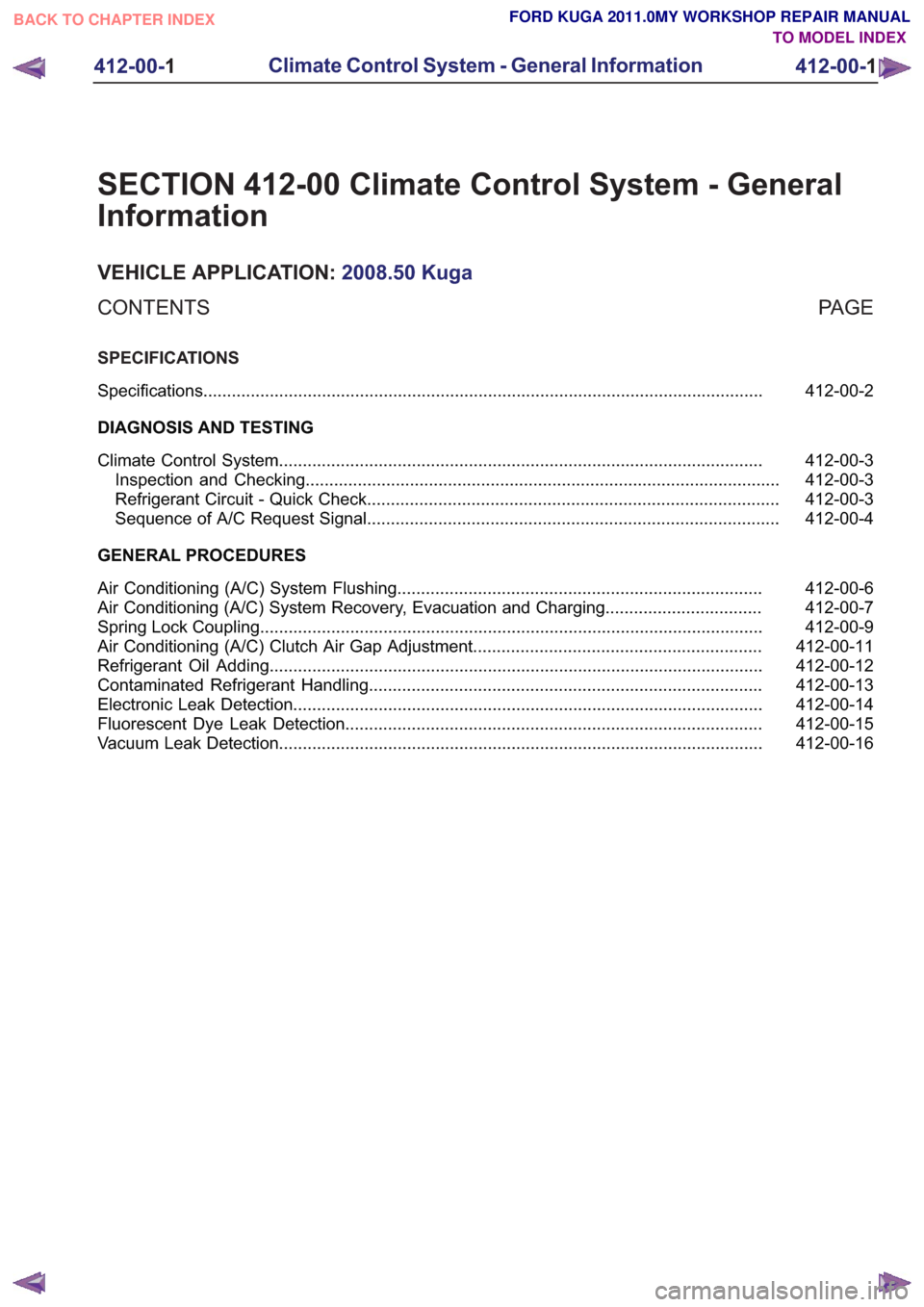
SECTION 412-00 Climate Control System - General
Information
VEHICLE APPLICATION:2008.50 Kuga
PA G E
CONTENTS
SPECIFICATIONS
412-00-2
Specifications ........................................................................\
..............................................
DIAGNOSIS AND TESTING 412-00-3
Climate Control System ........................................................................\
..............................
412-00-3
Inspection and Checking ........................................................................\
............................
412-00-3
Refrigerant Circuit - Quick Check ........................................................................\
...............
412-00-4
Sequence of A/C Request Signal ........................................................................\
...............
GENERAL PROCEDURES 412-00-6
Air Conditioning (A/C) System Flushing ........................................................................\
.....
412-00-7
Air Conditioning (A/C) System Recovery, Evacuation and Charging .................................
412-00-9
Spring Lock Coupling ........................................................................\
..................................
412-00-11
Air Conditioning (A/C) Clutch Air Gap Adjustment .............................................................
412-00-12
Refrigerant Oil Adding ........................................................................\
................................
412-00-13
Contaminated Refrigerant Handling ........................................................................\
...........
412-00-14
Electronic Leak Detection ........................................................................\
...........................
412-00-15
Fluorescent Dye Leak Detection ........................................................................\
................
412-00-16
Vacuum Leak Detection ........................................................................\
..............................
412-00-1
Climate Control System - General Information
412-00- 1
.
TO MODEL INDEX
BACK TO CHAPTER INDEX
FORD KUGA 2011.0MY WORKSHOP REPAIR MANUAL
Page 2020 of 2057
Spring Lock Coupling
Special Tool(s)412-026
Disconnect Tool, Spring Lock
Coupling (3/8" red)
23023A
412-027
Disconnect Tool, Spring Lock
Coupling (1/2" blue)
34001
412-038
Disconnect Tool, Spring Lock
Coupling (5/8" black)
34003
412-069
Disconnect Tool, Spring Lock
Coupling (3/4" white)
34002
Materials
Specification
Name
WSH-M1C231-B /
6U7J-M1C231-AA
Compressor Oil - Air
Conditioning 1.
Refer to: Air Conditioning (A/C) System Health
and Safety Precautions (100-00 General
Information, Description and Operation).
2. NOTE: Choose the special tool according to the
line diameter.
Special Tool(s): 412-026, 412-027, 412-038,
412-069
E68499
3.
E68500
4. CAUTION: Make sure that all openings are sealed.
E68501
G549834en2008.50 Kuga8/2011
412-00- 9
Climate Control System - General Information
412-00- 9
GENERAL PROCEDURES
TO MODEL INDEX
BACK TO CHAPTER INDEX
FORD KUGA 2011.0MY WORKSHOP REPAIR MANUAL
Page 2021 of 2057
5. CAUTION: Make sure that all openingsare sealed.
• Check the locking spring for damage.
• Carefully remove damaged locking springswith a thin wire, and renew them.
E68502
6.Install new refrigerant line O-rings.
E68523
7. CAUTION: Never lubricate connections
and O-rings with mineral oil.
Coat the O-rings for the refrigerant line with
clean refrigerant oil.
Material: Compressor Oil - Air Conditioning(WSH-M1C231-B / 6U7J-M1C231-AA)
refrigerant oil
8.
E68503
G549834en2008.50 Kuga8/2011
412-00- 10
Climate Control System - General Information
412-00- 10
GENERAL PROCEDURES
TO MODEL INDEX
BACK TO CHAPTER INDEX
FORD KUGA 2011.0MY WORKSHOP REPAIR MANUAL
Page 2026 of 2057

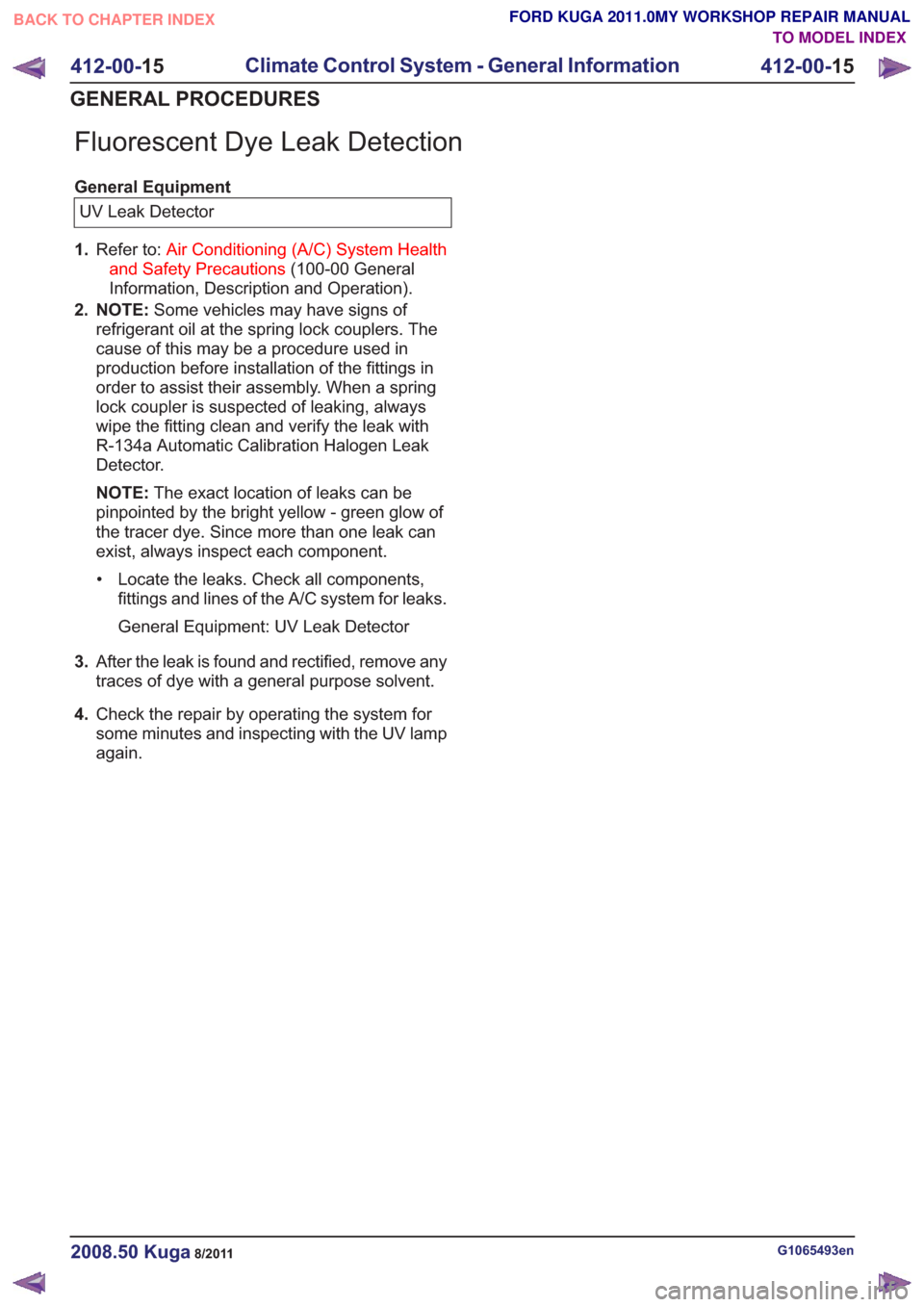
Fluorescent Dye Leak Detection
General EquipmentUV Leak Detector
1. Refer to: Air Conditioning (A/C) System Health
and Safety Precautions (100-00 General
Information, Description and Operation).
2. NOTE: Some vehicles may have signs of
refrigerant oil at the spring lock couplers. The
cause of this may be a procedure used in
production before installation of the fittings in
order to assist their assembly. When a spring
lock coupler is suspected of leaking, always
wipe the fitting clean and verify the leak with
R-134a Automatic Calibration Halogen Leak
Detector.
NOTE: The exact location of leaks can be
pinpointed by the bright yellow - green glow of
the tracer dye. Since more than one leak can
exist, always inspect each component.
• Locate the leaks. Check all components, fittings and lines of the A/C system for leaks.
General Equipment: UV Leak Detector
3. After the leak is found and rectified, remove any
traces of dye with a general purpose solvent.
4. Check the repair by operating the system for
some minutes and inspecting with the UV lamp
again.
G1065493en2008.50 Kuga8/2011
412-00- 15
Climate Control System - General Information
412-00- 15
GENERAL PROCEDURES
TO MODEL INDEX
BACK TO CHAPTER INDEX
FORD KUGA 2011.0MY WORKSHOP REPAIR MANUAL
Page 2051 of 2057

permitted, the high-pressure switch turns off the
refrigerant compressor.
The compressor on-off cycle is controlled by the
dual pressure switch depending on the pressure
in the refrigerant accumulator. The dual pressure
switch turns the refrigerant compressor off
permanently if the pressure falls below a permitted
value (e.g. if there is a leak).
Component Description
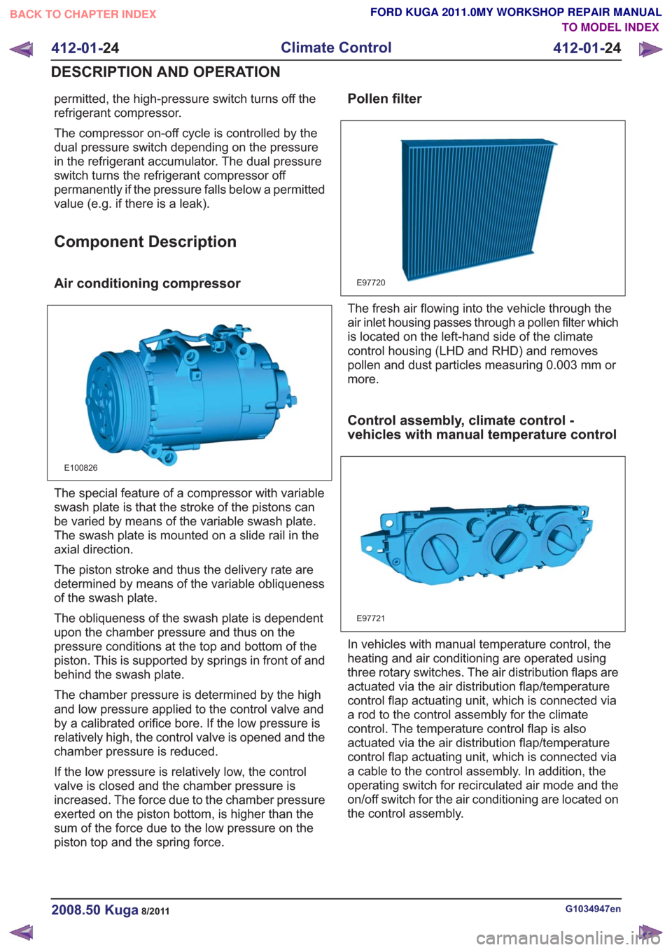
Air conditioning compressor
E100826
The special feature of a compressor with variable
swash plate is that the stroke of the pistons can
be varied by means of the variable swash plate.
The swash plate is mounted on a slide rail in the
axial direction.
The piston stroke and thus the delivery rate are
determined by means of the variable obliqueness
of the swash plate.
The obliqueness of the swash plate is dependent
upon the chamber pressure and thus on the
pressure conditions at the top and bottom of the
piston. This is supported by springs in front of and
behind the swash plate.
The chamber pressure is determined by the high
and low pressure applied to the control valve and
by a calibrated orifice bore. If the low pressure is
relatively high, the control valve is opened and the
chamber pressure is reduced.
If the low pressure is relatively low, the control
valve is closed and the chamber pressure is
increased. The force due to the chamber pressure
exerted on the piston bottom, is higher than the
sum of the force due to the low pressure on the
piston top and the spring force.
Pollen filter
E97720
The fresh air flowing into the vehicle through the
air inlet housing passes through a pollen filter which
is located on the left-hand side of the climate
control housing (LHD and RHD) and removes
pollen and dust particles measuring 0.003 mm or
more.
Control assembly, climate control -
vehicles with manual temperature control
E97721
In vehicles with manual temperature control, the
heating and air conditioning are operated using
three rotary switches. The air distribution flaps are
actuated via the air distribution flap/temperature
control flap actuating unit, which is connected via
a rod to the control assembly for the climate
control. The temperature control flap is also
actuated via the air distribution flap/temperature
control flap actuating unit, which is connected via
a cable to the control assembly. In addition, the
operating switch for recirculated air mode and the
on/off switch for the air conditioning are located on
the control assembly.
G1034947en2008.50 Kuga8/2011
412-01-24
Climate Control
412-01- 24
DESCRIPTION AND OPERATION
TO MODEL INDEX
BACK TO CHAPTER INDEX
FORD KUGA 2011.0MY WORKSHOP REPAIR MANUAL