2011 FORD KUGA Rf key
[x] Cancel search: Rf keyPage 458 of 2057

Turn signals
Description
Item
External mirror housing
1
Turn signals
2
The GEM switches the direction indicators and the
direction indicator side repeaters on.
The GEM sends a signal to the instrument cluster
via the CAN bus to switch on the relevant turn
indicator and the acoustic signal.
The signals from the hazard flasher switch and
from the multifunction switch are transmitted to the
GEM via a wiring connection.
The turn signals and the warning lamp flash at a
specified frequency and, in the case of failure of a
turn signal, the frequency is doubled.
The turn signal lamps also have a one-touch lane
change function. If the multifunction lever is
pressed just slightly then the relevant turn signal
lamp is actuated 3 times by the GEM.
Interior lighting
Depending on the vehicle specification, the interior
lighting includes:
• Left and right-hand footwell lamps
• Overhead lights at front and rear
Depending on the vehicle specification, the
switchable interior lighting includes:
• Map lights
• Mirror lights in sun visors
• Glove compartment lamp
• Luggage compartment lamp
The front and rear overhead lights are switched on
by the GEM. The interior lighting is switched on if one of the
following conditions is satisfied:
One of the vehicle's doors is opened.
The ignition key is in the "0" or "I" position and the
vehicle is unlocked.
The ignition key is turned from the "II" to the "I" or
"0" position.
The interior lighting is switched off when all of the
doors are closed and one of the following
conditions is satisfied:
• 25 seconds have elapsed since the last door
was closed.
• The ignition key is turned from the "0" or "I" to the "II" position.
• The ignition key is in the "0" or "I" position while the vehicle is locked.
The dimmer function is not used if the interior
lighting is switched off via the battery protection
function.
Heated windscreen
The heated windshield is switched on by the GEM
under the following conditions:
• The heated windshield switch is operated, the ignition switch is in position "II" and the charge
warning lamp is switched off.
• The "Defrost" function of the two-zone air conditioning has been activated, the ignition
switch is in the position "II" and the charge
warning lamp is off.
• The battery voltage has exceeded 16 V for more
than 20 seconds (power management strategy).
Manual requests for switching off the heated
windshield by pressing the switch are ignored
at this time.
• The engine was started at an outside air temperature below 4°C and an engine
temperature below 65°. Manual requests for
switching off the heated windshield by pressing
the switch are accepted.
NOTE: If the battery voltage returns to the normal
range, the disabling of the heated windshield is
switched off. It is then switched off.
The heated windshield is switched off by the GEM
under the following conditions: G1030788en
2008.50 Kuga 8/2011 419-10-8
Multifunction Electronic Modules
419-10-8
DESCRIPTION AND OPERATIONTO MODEL INDEX
BACK TO CHAPTER INDEX
FORD KUGA 2011.0MY WORKSHOP REPAIR MANUAL12E98941
Page 461 of 2057

Generic Electronic Module (GEM)
Refer to Wiring Diagrams Section 419-10, for
schematic and connector information.
Special Tool(s) / General Equipment
Terminal Probe Kit
418-S035Digital multimeter
Ford approved diagnostic tool
Description of operation
A diagnosis of the generic electronic module (GEM)
can be performed with the Ford approved
diagnostic tool. Furthermore, an integrated service
mode enables testing of the input and output
signals without the need for further tools. To enable
activation of service mode:
• Switch off the ignition
• Switch off all other electrical consumers
• Apply the handbrake
• Shift to neutral
• Close the doors.
Activate service mode
Proceed as follows to activate service mode:
• PRESS and HOLD the switch of the heated rear
window
• SWITCH ON the ignition.
• RELEASE the switch of the heated rear window
A signal sounds and the turn signal lamps
illuminate to indicate that service mode has been
successfully activated.
NOTE: If the alarm is armed (in vehicles fitted with
an anti-theft alarm system), service mode cannot
be activated.
Input signals
SWITCH the windshield wiper switch to the "Off"
position to test the input signals. The following is
a list of the switch signals to be tested, in no
particular order: • Turn signals (right, left, hazard warning lights)
• Windshield wiper stage I
• Windshield wiper stage II
• Windshield washer system
• Rear window wiper
• Rear window washer system
• Doors open/closed
• Door key cylinder set/reset switch
• Remote control for central locking with double
locking
• Hood up/down (in vehicles fitted with anti-theft alarm system)
• Tailgate open/closed
• Mini liftgate open/closed
• Manual A/C request signal
• Manual AUX heater request signal
• Heated windshield (if fitted)
• Parking brake
• Brake fluid level
• Cruise control system
• Autolamps
• Dipped beam
• Main beam
• Headlamp flasher
• Side lights
• Reversing lamp
• Tailgate release
• Mini liftgate release
• Interior scanning system
• Ignition switch, terminal 15 (turn key to 0 position, then turn key to II position.)
An acoustic signal sounds and the turn signal
lamps flash to indicate receipt of each input signal
by the generic electronic module.
Test the windshield wiper "intermittent mode" stage
input signal (only vehicles with adjustable
intermittent mode)
The windshield wiper switch must be switched to
"intermittent mode" in order to test the input signal.
The delay times of the input signals can then be
tested by operating the rotary switch. Each change
of the rotary switch position is indicated by an
acoustic signal and illumination of the turn signals. G1055084en
2008.50 Kuga 8/2011 419-10-11
Multifunction Electronic Modules
419-10-11
DIAGNOSIS AND TESTINGTO MODEL INDEX
BACK TO CHAPTER INDEX
FORD KUGA 2011.0MY WORKSHOP REPAIR MANUAL29011A
Page 464 of 2057

Generic Electronic Module (GEM)
General Equipment
Ford Diagnostic Equipment
Removal
CAUTIONS: Modules must not be swapped between
vehicles.
Compare the number of relays and fuses
in the defective GEM and the new GEM.
Transfer from the defective GEM any relays
and fuses which are not in the new GEM.
In doing so, pay attention that fuses with
the correct Ampere rating are used, by
referring to the wiring diagrams.
When installing a new GEM on vehicles
with a diesel engine, make sure that a fuel
pump fuse (F111) with 5A is used.
When installing a new GEM on vehicles
with a petrol engine, make sure that a fuel
pump fuse (F111) with 15A is used.
NOTE: GEM is integrated into the central junction
box (CJB) and cannot be removed individually.
1. NOTE: This step is only necessary when
installing a new component.
Upload the GEM configuration information using
the Programmable Modules Installation Routine.
General Equipment: Ford Diagnostic Equipment
2. Refer to: Battery Disconnect and Connect
(414-01 Battery, Mounting and Cables,
General Procedures).
3. 4.
5.
Installation
1.
To install, reverse the removal procedure.
2. NOTE: This step is only necessary when
installing a new component.
Download the GEM configuration information
to the newly installed GEM using the
programmable modules installation routine.
3. NOTE: This step is only necessary when
installing a new component.
Program all keys using the Key Programming
Routine.
General Equipment: Ford Diagnostic Equipment G1065605en
2008.50 Kuga 8/2011 419-10-14
Multifunction Electronic Modules
419-10-14
REMOVAL AND INSTALLATIONTO MODEL INDEX
BACK TO CHAPTER INDEX
FORD KUGA 2011.0MY WORKSHOP REPAIR MANUALE51159 122E102019 E102020
Page 1202 of 2057
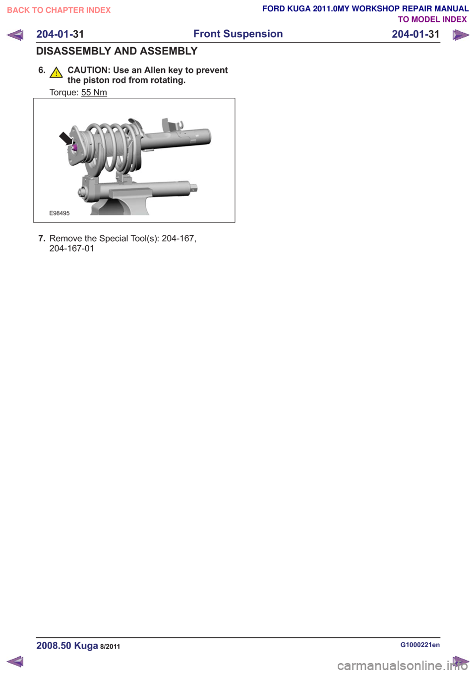
6. CAUTION: Use an Allen key to preventthe piston rod from rotating.
Torque: 55Nm
E98495
7.Remove the Special Tool(s): 204-167,
204-167-01
G1000221en2008.50 Kuga8/2011
204-01- 31
Front Suspension
204-01- 31
DISASSEMBLY AND ASSEMBLY
TO MODEL INDEX
BACK TO CHAPTER INDEX
FORD KUGA 2011.0MY WORKSHOP REPAIR MANUAL
Page 1422 of 2057
Description
Item
Front wheel sensor, right-hand side
8Description
Item
9 ESP switch
Testing the brakes on a roller dynamometer
- 4X4 vehicles only
On 4X4 vehicles a brake test on a roller
dynamometer must only be performed under the
following conditions.
• The brake test must not exceed a duration of 1 minute.
• Ignition key in position 0.
• The roller speed must not exceed 5 km/h.
ABS/ESP module or hydraulic control
unit (HCU)
E96821
1
23
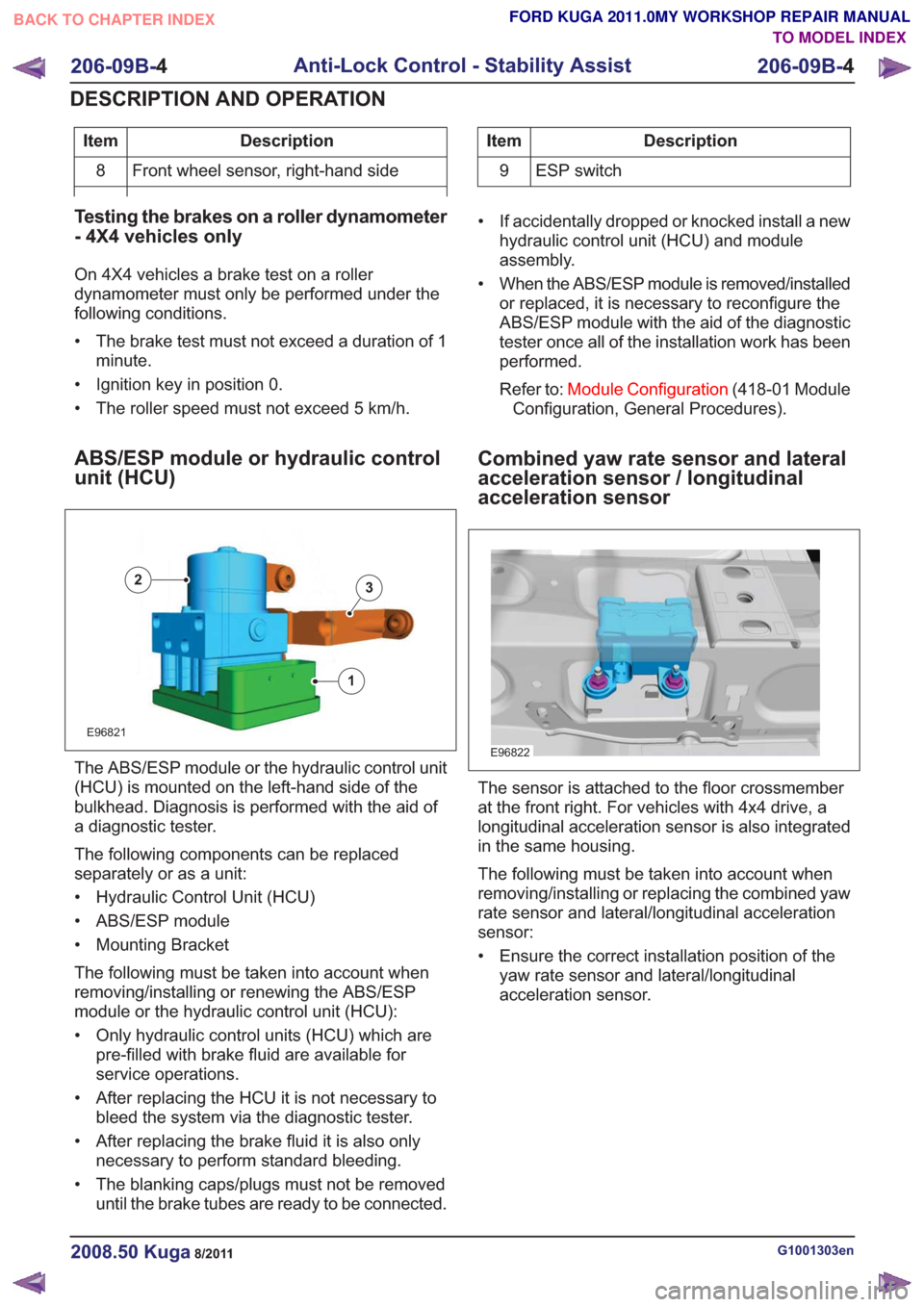
The ABS/ESP module or the hydraulic control unit
(HCU) is mounted on the left-hand side of the
bulkhead. Diagnosis is performed with the aid of
a diagnostic tester.
The following components can be replaced
separately or as a unit:
• Hydraulic Control Unit (HCU)
• ABS/ESP module
• Mounting Bracket
The following must be taken into account when
removing/installing or renewing the ABS/ESP
module or the hydraulic control unit (HCU):
• Only hydraulic control units (HCU) which are pre-filled with brake fluid are available for
service operations.
• After replacing the HCU it is not necessary to bleed the system via the diagnostic tester.
• After replacing the brake fluid it is also only necessary to perform standard bleeding.
• The blanking caps/plugs must not be removed until the brake tubes are ready to be connected. • If accidentally dropped or knocked install a new
hydraulic control unit (HCU) and module
assembly.
• When the ABS/ESP module is removed/installed or replaced, it is necessary to reconfigure the
ABS/ESP module with the aid of the diagnostic
tester once all of the installation work has been
performed.
Refer to: Module Configuration (418-01 Module
Configuration, General Procedures).
Combined yaw rate sensor and lateral
acceleration sensor / longitudinal
acceleration sensor
E96822
The sensor is attached to the floor crossmember
at the front right. For vehicles with 4x4 drive, a
longitudinal acceleration sensor is also integrated
in the same housing.
The following must be taken into account when
removing/installing or replacing the combined yaw
rate sensor and lateral/longitudinal acceleration
sensor:
• Ensure the correct installation position of the yaw rate sensor and lateral/longitudinal
acceleration sensor.
G1001303en2008.50 Kuga8/2011
206-09B- 4
Anti-Lock Control - Stability Assist
206-09B- 4
DESCRIPTION AND OPERATION
TO MODEL INDEX
BACK TO CHAPTER INDEX
FORD KUGA 2011.0MY WORKSHOP REPAIR MANUAL
Page 1714 of 2057
Throttle Body(23 198 0)
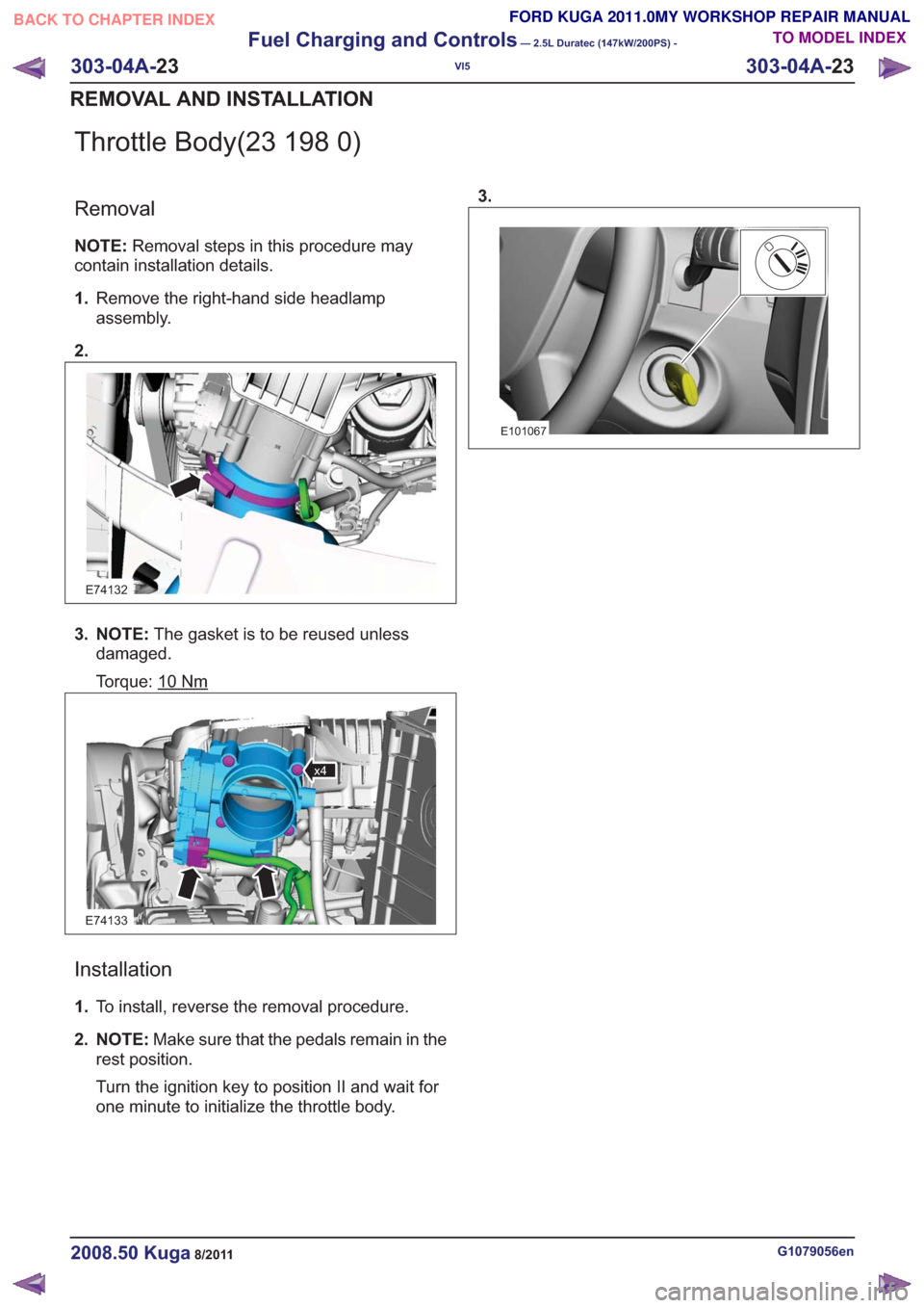
Removal
NOTE:Removal steps in this procedure may
contain installation details.
1. Remove the right-hand side headlamp
assembly.
2.
E74132
3. NOTE: The gasket is to be reused unless
damaged.
Torque: 10
Nm
E74133
x4
Installation
1. To install, reverse the removal procedure.
2. NOTE: Make sure that the pedals remain in the
rest position.
Turn the ignition key to position II and wait for
one minute to initialize the throttle body. 3.
E101067
G1079056en2008.50 Kuga8/2011
303-04A-
23
Fuel Charging and Controls
— 2.5L Duratec (147kW/200PS) -
VI5
303-04A- 23
REMOVAL AND INSTALLATION
TO MODEL INDEX
BACK TO CHAPTER INDEX
FORD KUGA 2011.0MY WORKSHOP REPAIR MANUAL
Page 1747 of 2057
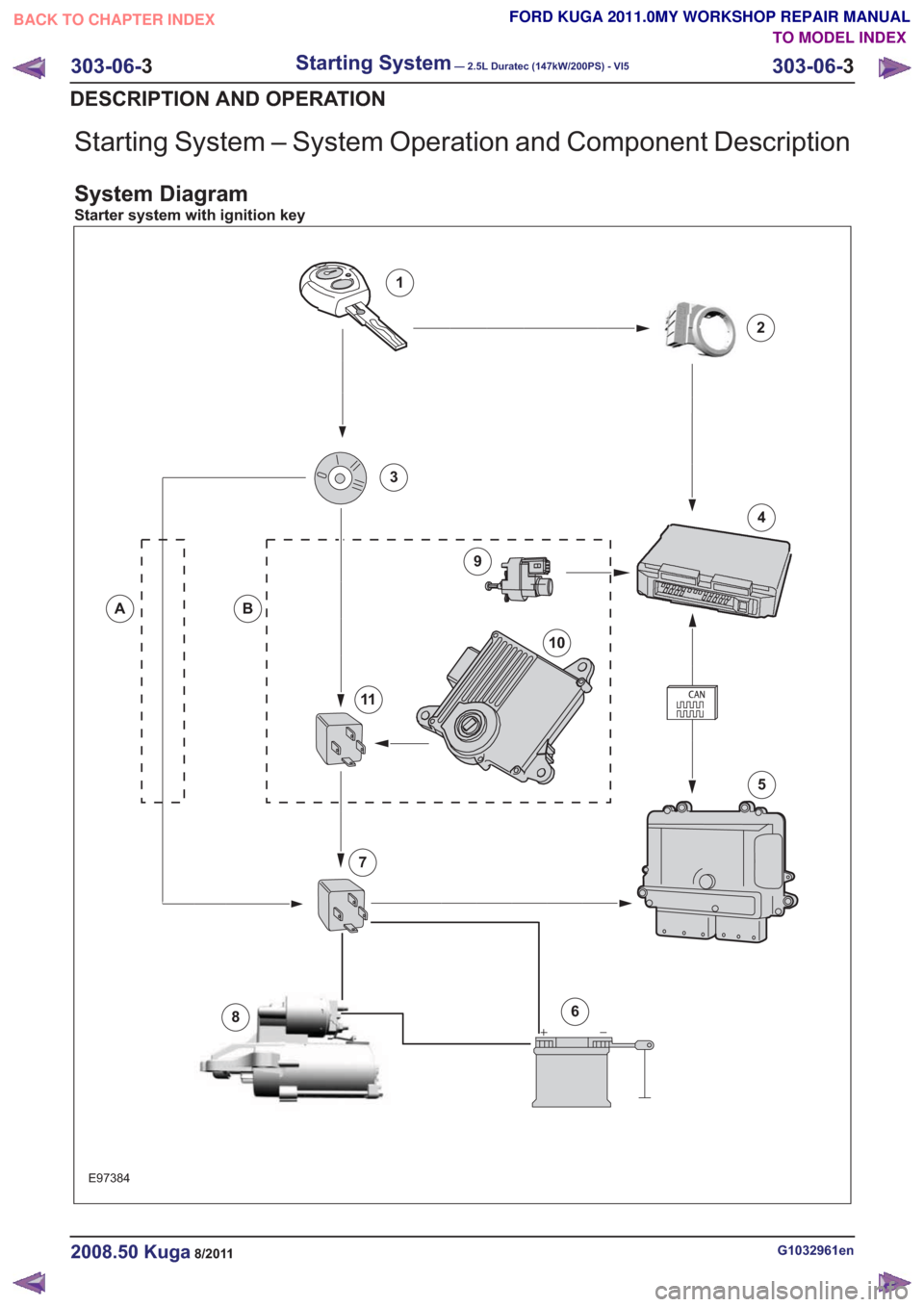
Starting System – System Operation and Component Description
System Diagram
Starter system with ignition key
E97384
1
2
4
6
5
8
9
10
11
3
BA
7
G1032961en2008.50 Kuga8/2011
303-06-3
Starting System— 2.5L Duratec (147kW/200PS) - VI5303-06-
3
DESCRIPTION AND OPERATION
TO MODEL INDEX
BACK TO CHAPTER INDEX
FORD KUGA 2011.0MY WORKSHOP REPAIR MANUAL
Page 1748 of 2057
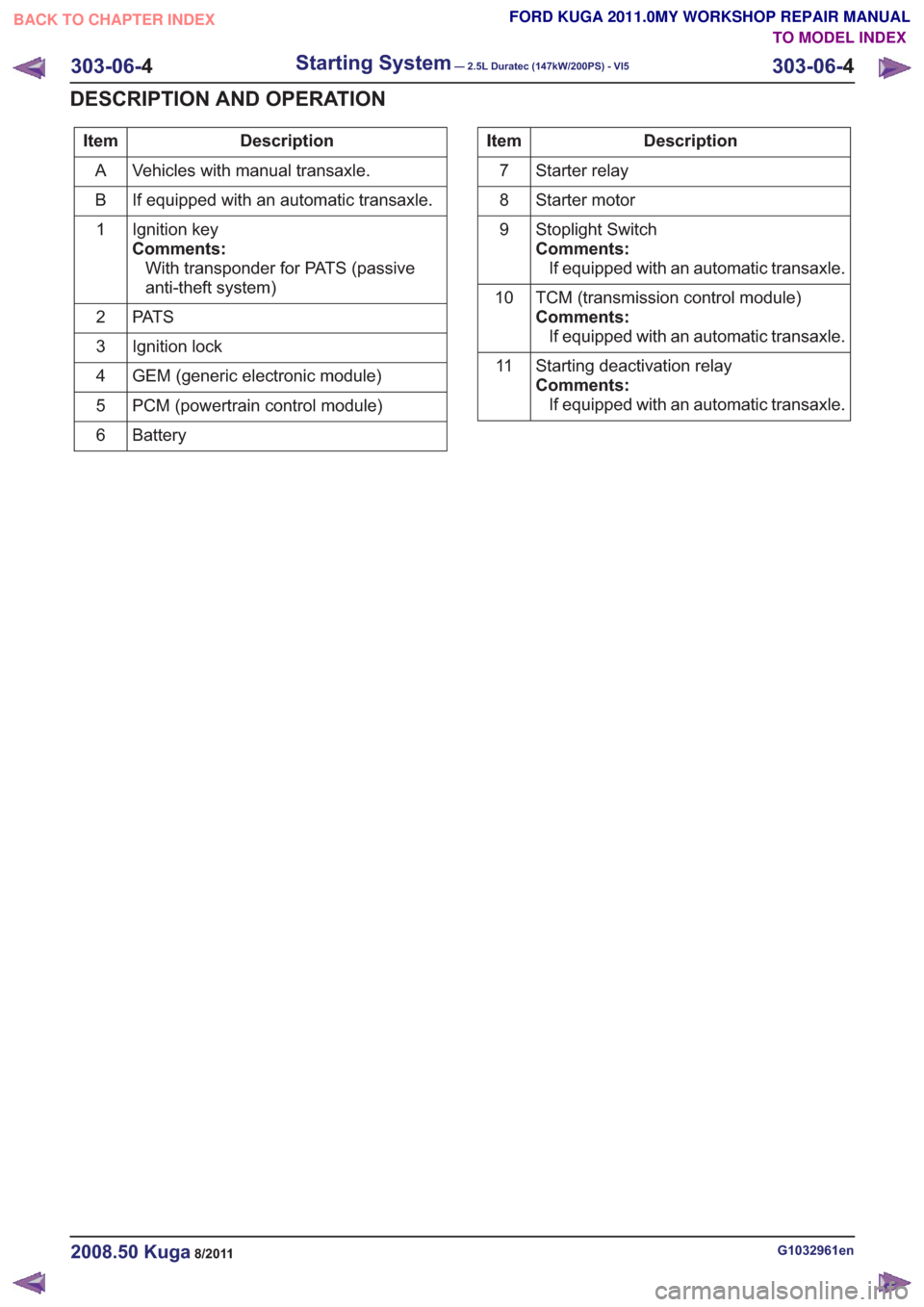
Description
Item
Vehicles with manual transaxle.
A
If equipped with an automatic transaxle.
B
Ignition key
Comments:With transponder for PATS (passive
anti-theft system)
1
PAT S
2
Ignition lock
3
GEM (generic electronic module)
4
PCM (powertrain control module)
5
Battery
6Description
Item
Starter relay
7
Starter motor
8
Stoplight Switch
Comments:If equipped with an automatic transaxle.
9
TCM (transmission control module)
Comments:If equipped with an automatic transaxle.
10
Starting deactivation relay
Comments:If equipped with an automatic transaxle.
11
G1032961en2008.50 Kuga8/2011
303-06-
4
Starting System— 2.5L Duratec (147kW/200PS) - VI5303-06-
4
DESCRIPTION AND OPERATION
TO MODEL INDEX
BACK TO CHAPTER INDEX
FORD KUGA 2011.0MY WORKSHOP REPAIR MANUAL