2011 FORD KUGA AUX
[x] Cancel search: AUXPage 460 of 2057

Windshield wash/wipe system
Refer to:
Wipers and Washers (501-16 Wipers and
Washers, Description and Operation).
Anti-theft
Refer to: Anti-Theft - Active (419-01 Anti-Theft -
Active, Description and Operation).
Electric booster Heater
Refer to: Auxiliary Climate Control (412-02 Auxiliary
Climate Control, Description and Operation).
Climate control
Refer to: Climate Control (412-01 Climate Control,
Description and Operation). G1030788en
2008.50 Kuga 8/2011 419-10-10
Multifunction Electronic Modules
419-10-10
DESCRIPTION AND OPERATIONTO MODEL INDEX
BACK TO CHAPTER INDEX
FORD KUGA 2011.0MY WORKSHOP REPAIR MANUAL
Page 461 of 2057

Generic Electronic Module (GEM)
Refer to Wiring Diagrams Section 419-10, for
schematic and connector information.
Special Tool(s) / General Equipment
Terminal Probe Kit
418-S035Digital multimeter
Ford approved diagnostic tool
Description of operation
A diagnosis of the generic electronic module (GEM)
can be performed with the Ford approved
diagnostic tool. Furthermore, an integrated service
mode enables testing of the input and output
signals without the need for further tools. To enable
activation of service mode:
• Switch off the ignition
• Switch off all other electrical consumers
• Apply the handbrake
• Shift to neutral
• Close the doors.
Activate service mode
Proceed as follows to activate service mode:
• PRESS and HOLD the switch of the heated rear
window
• SWITCH ON the ignition.
• RELEASE the switch of the heated rear window
A signal sounds and the turn signal lamps
illuminate to indicate that service mode has been
successfully activated.
NOTE: If the alarm is armed (in vehicles fitted with
an anti-theft alarm system), service mode cannot
be activated.
Input signals
SWITCH the windshield wiper switch to the "Off"
position to test the input signals. The following is
a list of the switch signals to be tested, in no
particular order: • Turn signals (right, left, hazard warning lights)
• Windshield wiper stage I
• Windshield wiper stage II
• Windshield washer system
• Rear window wiper
• Rear window washer system
• Doors open/closed
• Door key cylinder set/reset switch
• Remote control for central locking with double
locking
• Hood up/down (in vehicles fitted with anti-theft alarm system)
• Tailgate open/closed
• Mini liftgate open/closed
• Manual A/C request signal
• Manual AUX heater request signal
• Heated windshield (if fitted)
• Parking brake
• Brake fluid level
• Cruise control system
• Autolamps
• Dipped beam
• Main beam
• Headlamp flasher
• Side lights
• Reversing lamp
• Tailgate release
• Mini liftgate release
• Interior scanning system
• Ignition switch, terminal 15 (turn key to 0 position, then turn key to II position.)
An acoustic signal sounds and the turn signal
lamps flash to indicate receipt of each input signal
by the generic electronic module.
Test the windshield wiper "intermittent mode" stage
input signal (only vehicles with adjustable
intermittent mode)
The windshield wiper switch must be switched to
"intermittent mode" in order to test the input signal.
The delay times of the input signals can then be
tested by operating the rotary switch. Each change
of the rotary switch position is indicated by an
acoustic signal and illumination of the turn signals. G1055084en
2008.50 Kuga 8/2011 419-10-11
Multifunction Electronic Modules
419-10-11
DIAGNOSIS AND TESTINGTO MODEL INDEX
BACK TO CHAPTER INDEX
FORD KUGA 2011.0MY WORKSHOP REPAIR MANUAL29011A
Page 1523 of 2057
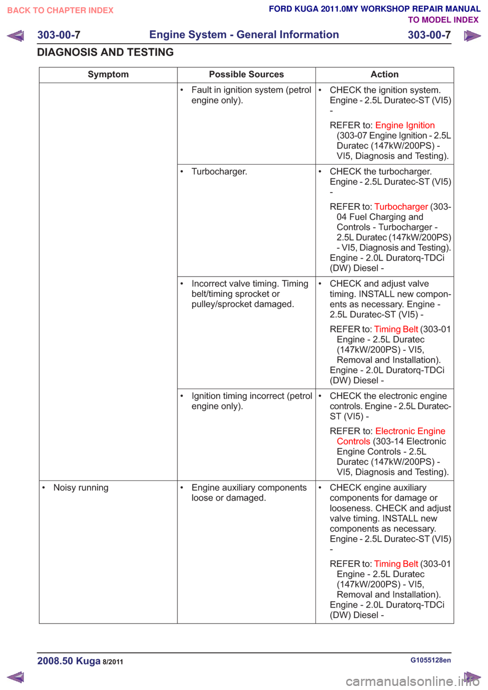
Action
Possible Sources
Symptom
• CHECK the ignition system.Engine - 2.5L Duratec-ST (VI5)
-
REFER to: Engine Ignition
(303-07 Engine Ignition - 2.5L
Duratec (147kW/200PS) -
VI5, Diagnosis and Testing).
• Fault in ignition system (petrol
engine only).
• CHECK the turbocharger.Engine - 2.5L Duratec-ST (VI5)
-
REFER to: Turbocharger (303-
04 Fuel Charging and
Controls - Turbocharger -
2.5L Duratec (147kW/200PS)
- VI5, Diagnosis and Testing).
Engine - 2.0L Duratorq-TDCi
(DW) Diesel -
• Turbocharger.
• CHECK and adjust valvetiming. INSTALL new compon-
ents as necessary. Engine -
2.5L Duratec-ST (VI5) -
REFER to: Timing Belt (303-01
Engine - 2.5L Duratec
(147kW/200PS) - VI5,
Removal and Installation).
Engine - 2.0L Duratorq-TDCi
(DW) Diesel -
• Incorrect valve timing. Timing
belt/timing sprocket or
pulley/sprocket damaged.
• CHECK the electronic enginecontrols. Engine - 2.5L Duratec-
ST (VI5) -
REFER to: Electronic Engine
Controls (303-14 Electronic
Engine Controls - 2.5L
Duratec (147kW/200PS) -
VI5, Diagnosis and Testing).
• Ignition timing incorrect (petrol
engine only).
• CHECK engine auxiliarycomponents for damage or
looseness. CHECK and adjust
valve timing. INSTALL new
components as necessary.
Engine - 2.5L Duratec-ST (VI5)
-
REFER to: Timing Belt (303-01
Engine - 2.5L Duratec
(147kW/200PS) - VI5,
Removal and Installation).
Engine - 2.0L Duratorq-TDCi
(DW) Diesel -
• Engine auxiliary components
loose or damaged.
• Noisy running
G1055128en2008.50 Kuga8/2011
303-00-
7
Engine System - General Information
303-00- 7
DIAGNOSIS AND TESTING
TO MODEL INDEX
BACK TO CHAPTER INDEX
FORD KUGA 2011.0MY WORKSHOP REPAIR MANUAL
Page 1672 of 2057
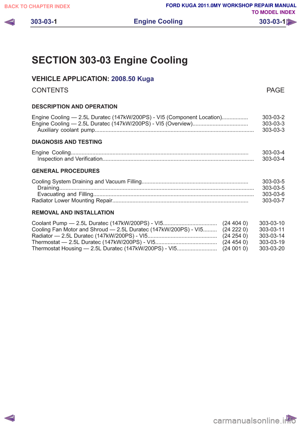
SECTION 303-03 Engine Cooling
VEHICLE APPLICATION:2008.50 Kuga
PA G E
CONTENTS
DESCRIPTION AND OPERATION
303-03-2
Engine Cooling — 2.5L Duratec (147kW/200PS) - VI5 (Component Location) .................
303-03-3
Engine Cooling — 2.5L Duratec (147kW/200PS) - VI5 (Overview) ....................................
303-03-3
Auxiliary coolant pump ........................................................................\
...............................
DIAGNOSIS AND TESTING 303-03-4
Engine Cooling ........................................................................\
...........................................
303-03-4
Inspection and Verification ........................................................................\
..........................
GENERAL PROCEDURES 303-03-5
Cooling System Draining and Vacuum Filling .....................................................................
303-03-5
Draining ........................................................................\
......................................................
303-03-6
Evacuating and Filling ........................................................................\
................................
303-03-7
Radiator Lower Mounting Repair ........................................................................\
................
REMOVAL AND INSTALLATION 303-03-10
(24 404 0)
Coolant Pump — 2.5L Duratec (147kW/200PS) - VI5 ...................................
303-03-11
(24 222 0)
Cooling Fan Motor and Shroud — 2.5L Duratec (147kW/200PS) - VI5 .........
303-03-14
(24 254 0)
Radiator — 2.5L Duratec (147kW/200PS) - VI5 .............................................
303-03-19
(24 454 0)
Thermostat — 2.5L Duratec (147kW/200PS) - VI5 ........................................
303-03-20
(24 001 0)
Thermostat Housing — 2.5L Duratec (147kW/200PS) - VI5 ..........................
303-03-1
Engine Cooling
303-03- 1
.
TO MODEL INDEX
BACK TO CHAPTER INDEX
FORD KUGA 2011.0MY WORKSHOP REPAIR MANUAL
Page 1673 of 2057
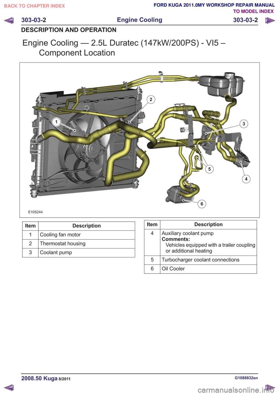
Engine Cooling — 2.5L Duratec (147kW/200PS) - VI5 –Component Location
E105244
1
2
3
4
5
6
Description
Item
Cooling fan motor
1
Thermostat housing
2
Coolant pump
3Description
Item
Auxiliary coolant pump
Comments:Vehicles equipped with a trailer coupling
or additional heating
4
Turbocharger coolant connections
5
Oil Cooler
6
G1088832en2008.50 Kuga8/2011
303-03- 2
Engine Cooling
303-03- 2
DESCRIPTION AND OPERATION
TO MODEL INDEX
BACK TO CHAPTER INDEX
FORD KUGA 2011.0MY WORKSHOP REPAIR MANUAL
Page 1674 of 2057
Engine Cooling — 2.5L Duratec (147kW/200PS) - VI5 – Overview
Auxiliary coolant pump
An electrically operated auxiliary coolant pump is
installed on vehicles with a trailer coupling and/or
additional heating. The auxiliary coolant pump
ensures that the coolant is circulated when the
coolant pump (which is driven by the engine) is not
running.
The additional heating uses the auxiliary coolant
pump to circulate hot coolant through the heat
exchanger and the engine.
On vehicles with a trailer coupling the auxiliary
coolant pump is switched on for 6 minutes by the
PCM (powertrain control module) if the coolant
temperature exceeds 106°C when the engine is
switched off. This prevents the coolant circuit from
overheating. This could happen particularly if the
engine is switched off after towing a heavy trailer
up a steep hill before there has been sufficient time
for cooling.
G1088220en2008.50 Kuga8/2011
303-03-3
Engine Cooling
303-03- 3
DESCRIPTION AND OPERATION
TO MODEL INDEX
BACK TO CHAPTER INDEX
FORD KUGA 2011.0MY WORKSHOP REPAIR MANUAL
Page 1828 of 2057
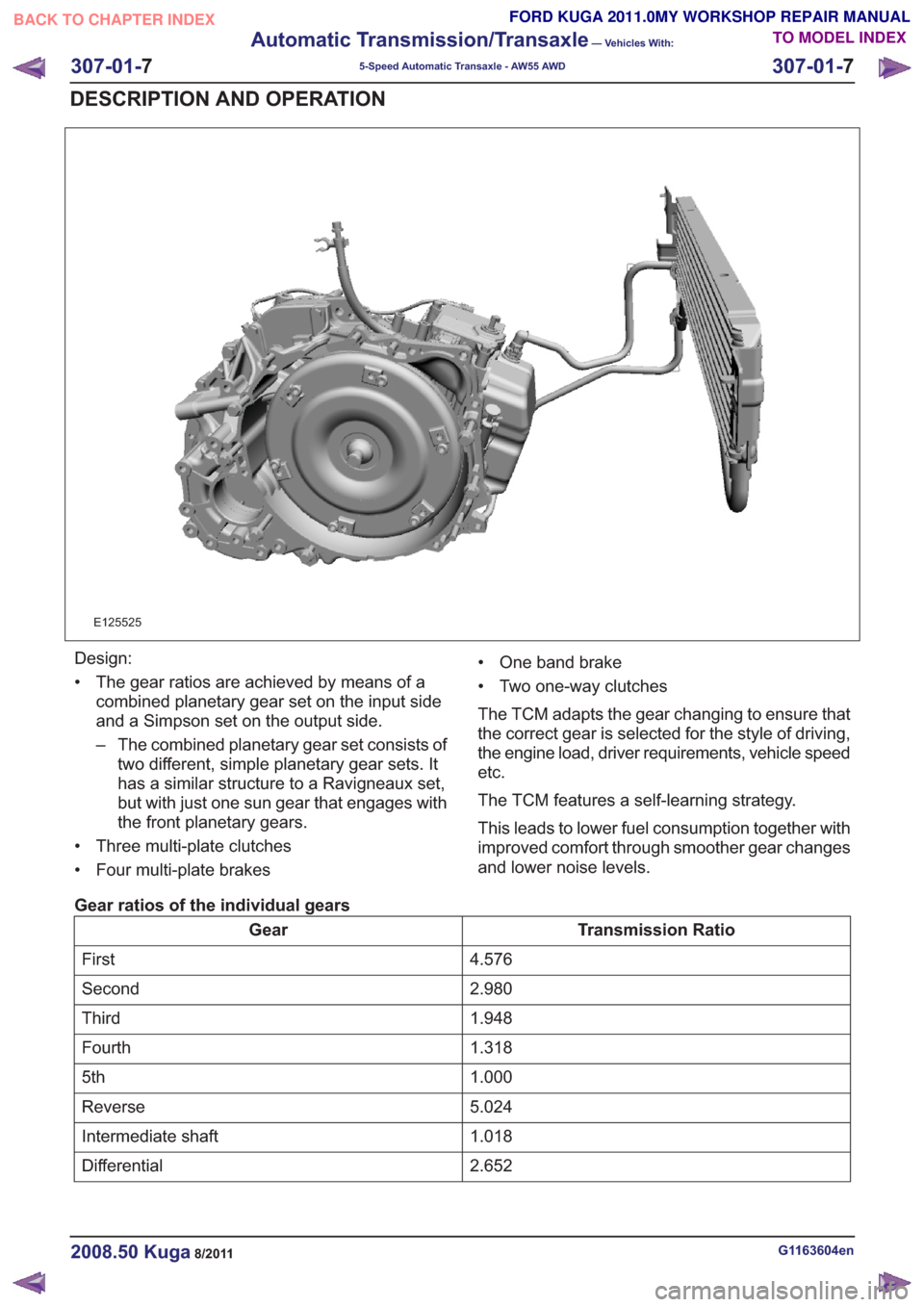
E125525
Design:
• The gear ratios are achieved by means of acombined planetary gear set on the input side
and a Simpson set on the output side.
– The combined planetary gear set consists oftwo different, simple planetary gear sets. It
has a similar structure to a Ravigneaux set,
but with just one sun gear that engages with
the front planetary gears.
• Three multi-plate clutches
• Four multi-plate brakes • One band brake
• Two one-way clutches
The TCM adapts the gear changing to ensure that
the correct gear is selected for the style of driving,
the engine load, driver requirements, vehicle speed
etc.
The TCM features a self-learning strategy.
This leads to lower fuel consumption together with
improved comfort through smoother gear changes
and lower noise levels.
Gear ratios of the individual gears
Transmission Ratio
Gear
4.576
First
2.980
Second
1.948
Third
1.318
Fourth
1.000
5th
5.024
Reverse
1.018
Intermediate shaft
2.652
Differential
G1163604en2008.50 Kuga8/2011
307-01- 7
Automatic Transmission/Transaxle
— Vehicles With:
5-Speed Automatic Transaxle - AW55 AWD
307-01- 7
DESCRIPTION AND OPERATION
TO MODEL INDEX
BACK TO CHAPTER INDEX
FORD KUGA 2011.0MY WORKSHOP REPAIR MANUAL