2011 FORD KUGA AIR CON
[x] Cancel search: AIR CONPage 1447 of 2057
Steering Gear Checks After a Collision
General EquipmentFeeler gauge
Straight edge
Items to be observed when checking the steering
system
The following list of steering gear conditions and
the methods of testing should be taken into account
when carrying out checks to the steering system:
• If the steering gear has no faults after completing the following checks, do not install
a new steering gear.
• Surface corrosion and marks on the tie-rod are acceptable.
• When checking for turning effort torque peaks in the steering gear, turn the steering wheel from
steering lock stop to steering lock stop in
approximately 15 seconds.
• A steady increase of turning effort torque from steering center to steering lock stop is
acceptable.
• When checking for power steering fluid leaks, turn the steering wheel to the steering lock stop
in approximately 10 seconds.
• Noises from the power steering, for example the power steering pump relief valve, are
acceptable.
STEERING GEAR HOUSING
1. Raise and support the vehicle. REFER to: Lifting(100-02 Jacking and Lifting,
Description and Operation).
2. Visually inspect the steering gear housing for cracks and damage. If the steering gear housing
is cracked or damaged, install a new steering
gear.
REFER to: Steering Gear (211-02 Power
Steering, Removal and Installation).
TIE-RODS
1. Using a straight edge and feeler gauge, check the tie-rods to see if they are straight. If the
distance between the tie-rod and straight edge is greater than 0.5 mm, install a new steering
gear.
REFER to:
Steering Gear (211-02 Power
Steering, Removal and Installation).
2. Check the tightening torque of the tie-rod end to wheel knuckle nut.
REFER to: Tie Rod End (211-03 Steering
Linkage, Removal and Installation).
3. Check the tightening torque of the tie-rod end locking nut.
REFER to: Tie Rod End (211-03 Steering
Linkage, Removal and Installation).
CHECK FOR TURNING EFFORT TORQUE
PEAKS IN THE STEERING GEAR
1. Lower and support the vehicle making sure that the road wheels are just clear of the floor.
2. With the ignition switch in position I, slowly turn the steering wheel from steering lock stop to
steering lock stop. If a turning effort torque peak
or judder is felt while turning the steering wheel,
detach the tie-rods from the wheel knuckles.
3. Slowly turn the steering wheel from steering lock stop to steering lock stop. If a turning effort
torque peak or judder is felt while turning the
steering wheel, install a new steering gear.
REFER to: Steering Gear (211-02 Power
Steering, Removal and Installation).
CHECK FOR POWER STEERING FLUID LEAKS
1. Lower the vehicle.
2. Run the engine at a fast idle and slowly turn the steering wheel to the left-hand steering lock
stop. Hold the steering wheel in this position for
5 seconds with a turning effort torque of 15 Nm
at the steering wheel rim.
3. Turn the steering wheel away from the left-hand steering lock stop for 30 seconds.
4. Run the engine at a fast idle and slowly turn the steering wheel to the right-hand steering lock
stop. Hold the steering wheel in this position for
5 seconds with a turning effort torque of 15 Nm
at the steering wheel rim.
5. Turn the steering wheel away from the right-hand steering lock stop.
6. Check for power steering fluid leaks at the steering gear housing and the power steering
line connections to the steering gear. If there is
G538091en2008.50 Kuga8/2011
211-00- 6
Steering System - General Information
211-00- 6
DIAGNOSIS AND TESTING
TO MODEL INDEX
BACK TO CHAPTER INDEX
FORD KUGA 2011.0MY WORKSHOP REPAIR MANUAL
Page 1449 of 2057
Power Steering System Flushing
MaterialsSpecification
Name
WSS-M2C204-A2 /
5U7J-M2C204-AA
Hydraulic Fluid DP-PS
1. WARNING: Be prepared to collect escaping fluids.
Using a blanking cap, cap the power steering
fluid reservoir.
E74090
2.Place the end of the steering gear return line
into a container.
3. Fill the power steering reservoir to the MAX
mark.
Material: Hydraulic Fluid DP-PS
(WSS-M2C204-A2 / 5U7J-M2C204-AA)
hydraulic fluid
4. Raise the vehicle until the road wheels are clear
of the floor. Support the vehicle.
Refer to: Lifting(100-02 Jacking and Lifting,
Description and Operation).
5. NOTE: This step requires the aid of another
technician.
1. Start the engine and slowly turn the steering from steering lock to steering lock until clean
power steering fluid comes out of the return
line.
2. With the aid of another technician, add the power steering fluid until the system is free
of contaminated power steering fluid.
Material: Hydraulic Fluid DP-PS(WSS-M2C204-A2 / 5U7J-M2C204-AA)
hydraulic fluid
G543411en2008.50 Kuga8/2011
211-00- 8
Steering System - General Information
211-00- 8
GENERAL PROCEDURES
TO MODEL INDEX
BACK TO CHAPTER INDEX
FORD KUGA 2011.0MY WORKSHOP REPAIR MANUAL
Page 1450 of 2057
Power Steering System Filling
Special Tool(s)211-189
Adapter, Power Steering
Bleeding
13016
416-D001
Hand Vacuum
Pump/Pressure Pump
23036A
Materials
Specification
Name
WSS-M2C204-A2 /
5U7J-M2C204-AA
Hydraulic Fluid DP-PS
1. Fill the power steering fluid reservoir to the MAX
mark.
Material: Hydraulic Fluid DP-PS
(WSS-M2C204-A2 / 5U7J-M2C204-AA)
hydraulic fluid
2. Raise the vehicle until the road wheels are clear
of the floor. Support the vehicle.
Refer to: Lifting(100-02 Jacking and Lifting,
Description and Operation).
3. Slowly turn the steering wheel from lock to lock
and add power steering fluid until the power
steering fluid in the power steering fluid reservoir
stops dropping.
4. Start the engine and slowly turn the steering
wheel from lock to lock and add power steering
fluid until the power steering fluid in the power
steering fluid reservoir stops dropping. 5.
Switch the engine OFF and using the special
tools, create a vacuum of 62cm-Hg - 75cm-Hg
for 30 seconds.
Special Tool(s): 211-189, 416-D001
E73916
211-189
416-D001
6. Observe the vacuum gauge reading.
1.
2. If the vacuum decreases by more than
5cm-Hg in 5 minutes, the system should be
checked for leaks.
7. Remove the special tools. Fill the power steering
fluid reservoir to the MAX mark as necessary.
Material: Hydraulic Fluid DP-PS
(WSS-M2C204-A2 / 5U7J-M2C204-AA)
hydraulic fluid
8. Lower the vehicle.
G543412en2008.50 Kuga8/2011
211-00- 9
Steering System - General Information
211-00- 9
GENERAL PROCEDURES
TO MODEL INDEX
BACK TO CHAPTER INDEX
FORD KUGA 2011.0MY WORKSHOP REPAIR MANUAL
Page 1458 of 2057
SECTION 211-02 Power Steering
VEHICLE APPLICATION:2008.50 Kuga
PA G E
CONTENTS
DESCRIPTION AND OPERATION
211-02-2
Power Steering (Component Location) ........................................................................\
......
211-02-3
Power Steering (Overview) ........................................................................\
.........................
211-02-3
Power Steering ........................................................................\
...........................................
211-02-4
Steering gear ........................................................................\
..............................................
211-02-5
Electro-hydraulic power steering pump ........................................................................\
......
211-02-6
Pressure and return lines ........................................................................\
...........................
211-02-7
Power Steering (System Operation and Component Description) .....................................
211-02-7
System Diagram ........................................................................\
.........................................
211-02-8
System Operation ........................................................................\
.......................................
211-02-8
Electronic principle of operation ........................................................................\
..............
211-02-9
Hydraulic principle of operation ........................................................................\
..............
211-02-9
Component Description ........................................................................\
..............................
211-02-9
Electro-hydraulic power steering pump ........................................................................\
..
211-02-10
Integrated steering angle sensor - vehicles built up to 09/2009 .....................................
211-02-11
Brushless DC motor with integral power steering module..............................................
REMOVAL AND INSTALLATION
211-02-13
(13 443 0)
Power Steering Pressure Line and Return Line Assembly — 2.5L Duratec
(147kW/200PS) - VI5 ........................................................................\
............
211-02-18
(13 434 0)
Power Steering Pump — 2.5L Duratec (147kW/200PS) - VI5 .......................
211-02-21
(13 440 0;
13 443 0)
Power Steering Pump to Steering Gear Pressure Line — 2.5L Duratec
(147kW/200PS) - VI5 ........................................................................\
............
211-02-25
(13 116 0)
Steering Gear ........................................................................\
.........................
211-02-36
(13 439 0)
Steering Gear to Power Steering Fluid Reservoir Return Line — 2.5L Duratec
(147kW/200PS) - VI5 ........................................................................\
............
211-02-1
Power Steering
211-02- 1
.
TO MODEL INDEX
BACK TO CHAPTER INDEX
FORD KUGA 2011.0MY WORKSHOP REPAIR MANUAL
Page 1460 of 2057
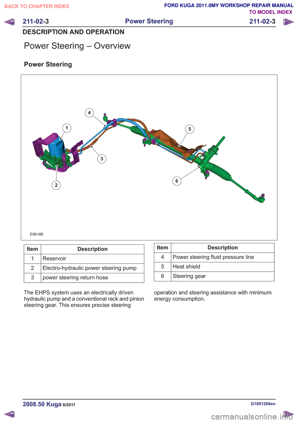
Power Steering – Overview
Power Steering
E96186
1
2
3
4
5
6
Description
Item
Reservoir
1
Electro-hydraulic power steering pump
2
power steering return hose
3Description
Item
Power steering fluid pressure line
4
Heat shield
5
Steering gear
6
The EHPS system uses an electrically driven
hydraulic pump and a conventional rack and pinion
steering gear. This ensures precise steering operation and steering assistance with minimum
energy consumption.
G1001269en2008.50 Kuga8/2011
211-02-
3
Power Steering
211-02- 3
DESCRIPTION AND OPERATION
TO MODEL INDEX
BACK TO CHAPTER INDEX
FORD KUGA 2011.0MY WORKSHOP REPAIR MANUAL
Page 1463 of 2057
• Rubber bushes, electro-hydraulic power steeringpump
• Bracket #1
• Bracket #2
During removal and installation or renewal of
components of the electro-hydraulic power steering
pump, pay attention to the following:
• Before starting work to renew the electro-hydraulic power steering pump, the
program code of the electro-hydraulic power steering must be read out using the diagnostic
unit and noted.
• After the work to renew the electro-hydraulic power steering pump is completed, the
electro-hydraulic power steering must be
reconfigured using the diagnostic unit. For
further information, see: Module Configuration
(418-01 Module Configuration, General
Procedures).
• The electro-hydraulic power steering pump must be filled and vented as specified.
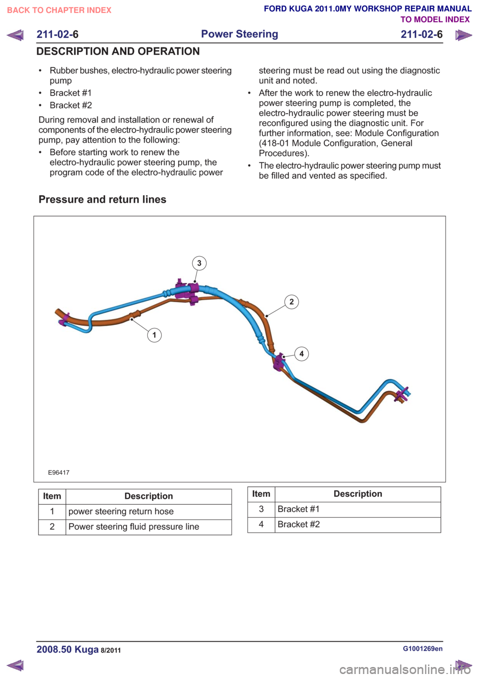
Pressure and return lines
E96417
1
2
3
4
Description
Item
power steering return hose
1
Power steering fluid pressure line
2Description
Item
Bracket #1
3
Bracket #2
4
G1001269en2008.50 Kuga8/2011
211-02- 6
Power Steering
211-02- 6
DESCRIPTION AND OPERATION
TO MODEL INDEX
BACK TO CHAPTER INDEX
FORD KUGA 2011.0MY WORKSHOP REPAIR MANUAL
Page 1465 of 2057
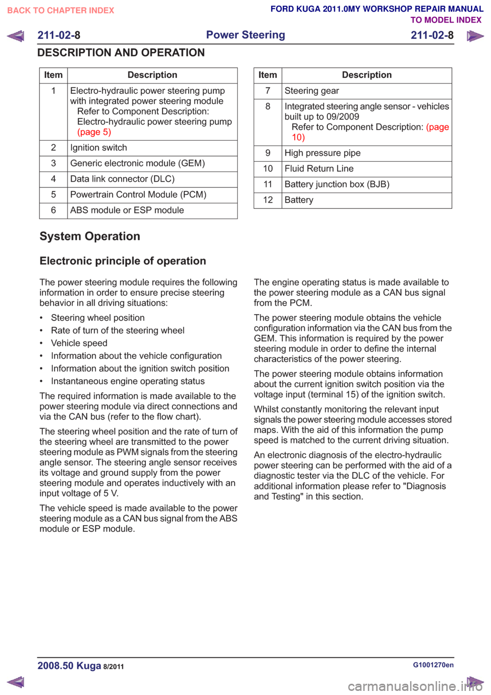
Description
Item
Electro-hydraulic power steering pump
with integrated power steering moduleRefer to Component Description:
Electro-hydraulic power steering pump
(page5)
1
Ignition switch
2
Generic electronic module (GEM)
3
Data link connector (DLC)
4
Powertrain Control Module (PCM)
5
ABS module or ESP module
6Description
Item
Steering gear
7
Integrated steering angle sensor - vehicles
built up to 09/2009RefertoComponentDescription:(page
10)
8
High pressure pipe
9
Fluid Return Line
10
Battery junction box (BJB)
11
Battery
12
System Operation
Electronic principle of operation
The power steering module requires the following
information in order to ensure precise steering
behavior in all driving situations:
• Steering wheel position
• Rate of turn of the steering wheel
• Vehicle speed
• Information about the vehicle configuration
• Information about the ignition switch position
• Instantaneous engine operating status
The required information is made available to the
power steering module via direct connections and
via the CAN bus (refer to the flow chart).
The steering wheel position and the rate of turn of
the steering wheel are transmitted to the power
steering module as PWM signals from the steering
angle sensor. The steering angle sensor receives
its voltage and ground supply from the power
steering module and operates inductively with an
input voltage of 5 V.
The vehicle speed is made available to the power
steering module as a CAN bus signal from the ABS
module or ESP module. The engine operating status is made available to
the power steering module as a CAN bus signal
from the PCM.
The power steering module obtains the vehicle
configuration information via the CAN bus from the
GEM. This information is required by the power
steering module in order to define the internal
characteristics of the power steering.
The power steering module obtains information
about the current ignition switch position via the
voltage input (terminal 15) of the ignition switch.
Whilst constantly monitoring the relevant input
signals the power steering module accesses stored
maps. With the aid of this information the pump
speed is matched to the current driving situation.
An electronic diagnosis of the electro-hydraulic
power steering can be performed with the aid of a
diagnostic tester via the DLC of the vehicle. For
additional information please refer to "Diagnosis
and Testing" in this section.
G1001270en2008.50 Kuga8/2011
211-02-
8
Power Steering
211-02- 8
DESCRIPTION AND OPERATION
TO MODEL INDEX
BACK TO CHAPTER INDEX
FORD KUGA 2011.0MY WORKSHOP REPAIR MANUAL
Page 1466 of 2057
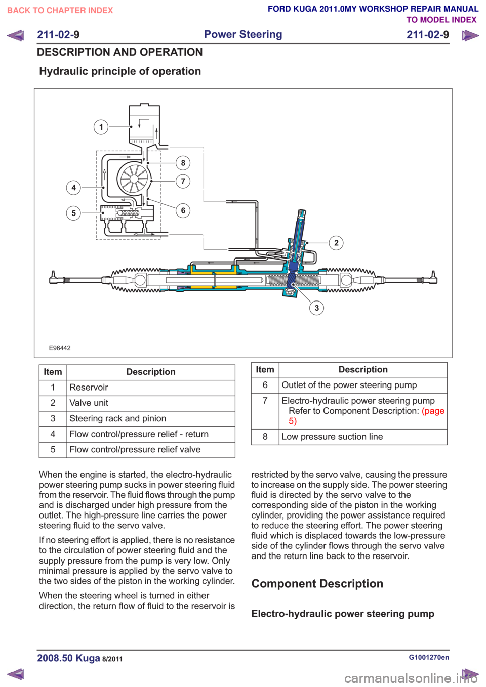
Hydraulic principle of operation
E96442
3
4
5
7
8
6
1
2
Description
Item
Reservoir
1
Valve unit
2
Steering rack and pinion
3
Flow control/pressure relief - return
4
Flow control/pressure relief valve
5Description
Item
Outlet of the power steering pump
6
Electro-hydraulic power steering pumpRefertoComponentDescription:(page
5)
7
Low pressure suction line
8
When the engine is started, the electro-hydraulic
power steering pump sucks in power steering fluid
from the reservoir. The fluid flows through the pump
and is discharged under high pressure from the
outlet. The high-pressure line carries the power
steering fluid to the servo valve.
If no steering effort is applied, there is no resistance
to the circulation of power steering fluid and the
supply pressure from the pump is very low. Only
minimal pressure is applied by the servo valve to
the two sides of the piston in the working cylinder.
When the steering wheel is turned in either
direction, the return flow of fluid to the reservoir is restricted by the servo valve, causing the pressure
to increase on the supply side. The power steering
fluid is directed by the servo valve to the
corresponding side of the piston in the working
cylinder, providing the power assistance required
to reduce the steering effort. The power steering
fluid which is displaced towards the low-pressure
side of the cylinder flows through the servo valve
and the return line back to the reservoir.
Component Description
Electro-hydraulic power steering pump
G1001270en2008.50 Kuga8/2011
211-02-
9
Power Steering
211-02- 9
DESCRIPTION AND OPERATION
TO MODEL INDEX
BACK TO CHAPTER INDEX
FORD KUGA 2011.0MY WORKSHOP REPAIR MANUAL