Page 1533 of 2057
TIE39704
35 Nm
9. Install the oil pressure switch.
TIE39595
10. Connect the oil pressure switch electricalconnector.
VFE0035742
11. Install the engine under shield.
12. Lower the vehicle.
Valve train analysis - static (engine off)
Remove the valve cover.
Check all valve train components for damage and
wear. Make sure that only original components are
installed and that all bolts and nuts have been
tightened to the correct tightening torque.
G1055128en2008.50 Kuga8/2011
303-00- 17
Engine System - General Information
303-00- 17
DIAGNOSIS AND TESTING
TO MODEL INDEX
BACK TO CHAPTER INDEX
FORD KUGA 2011.0MY WORKSHOP REPAIR MANUAL
Page 1534 of 2057

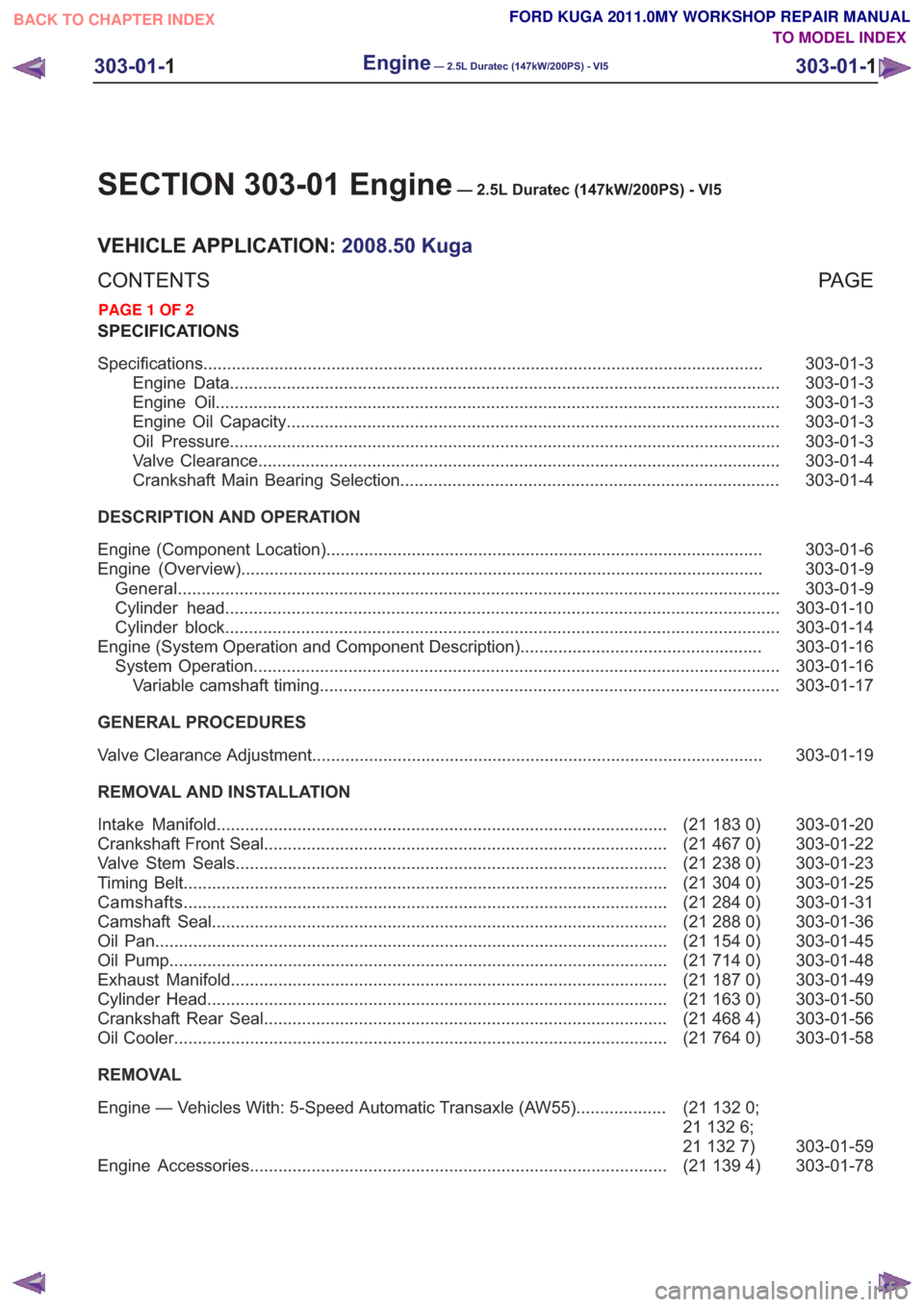
SECTION 303-01 Engine— 2.5L Duratec (147kW/200PS) - VI5
VEHICLE APPLICATION:2008.50 Kuga
PA G E
CONTENTS
SPECIFICATIONS
303-01-3
Specifications ........................................................................\
..............................................
303-01-3
Engine Data ........................................................................\
............................................
303-01-3
Engine Oil ........................................................................\
...............................................
303-01-3
Engine Oil Capacity ........................................................................\
................................
303-01-3
Oil Pressure ........................................................................\
............................................
303-01-4
Valve Clearance ........................................................................\
......................................
303-01-4
Crankshaft Main Bearing Selection ........................................................................\
........
DESCRIPTION AND OPERATION 303-01-6
Engine (Component Location) ........................................................................\
....................
303-01-9
Engine (Overview) ........................................................................\
......................................
303-01-9
General ........................................................................\
.......................................................
303-01-10
Cylinder head ........................................................................\
.............................................
303-01-14
Cylinder block ........................................................................\
.............................................
303-01-16
Engine (System Operation and Component Description) ...................................................
303-01-16
System Operation ........................................................................\
.......................................
303-01-17
Variable camshaft timing ........................................................................\
.........................
GENERAL PROCEDURES 303-01-19
Valve Clearance Adjustment ........................................................................\
.......................
REMOVAL AND INSTALLATION 303-01-20
(21 183 0)
Intake Manifold ........................................................................\
.......................
303-01-22
(21 467 0)
Crankshaft Front Seal ........................................................................\
.............
303-01-23
(21 238 0)
Valve Stem Seals ........................................................................\
...................
303-01-25
(21 304 0)
Timing Belt ........................................................................\
..............................
303-01-31
(21 284 0)
Camshafts ........................................................................\
..............................
303-01-36
(21 288 0)
Camshaft Seal ........................................................................\
........................
303-01-45
(21 154 0)
Oil Pan ........................................................................\
....................................
303-01-48
(21 714 0)
Oil Pump ........................................................................\
.................................
303-01-49
(21 187 0)
Exhaust Manifold ........................................................................\
....................
303-01-50
(21 163 0)
Cylinder Head ........................................................................\
.........................
303-01-56
(21 468 4)
Crankshaft Rear Seal ........................................................................\
.............
303-01-58
(21 764 0)
Oil Cooler ........................................................................\
................................
REMOVAL
303-01-59
(21
132 0;
21 132 6;
21 132 7)
Engine — Vehicles With: 5-Speed Automatic Transaxle (AW55)
...................
303-01-78
(21 139 4)
Engine Accessories ........................................................................\
................
303-01-1
Engine— 2.5L Duratec (147kW/200PS) - VI5303-01-
1
.
TO MODEL INDEX
BACK TO CHAPTER INDEX
PAGE 1 OF 2 FORD KUGA 2011.0MY WORKSHOP REPAIR MANUAL
Page 1537 of 2057

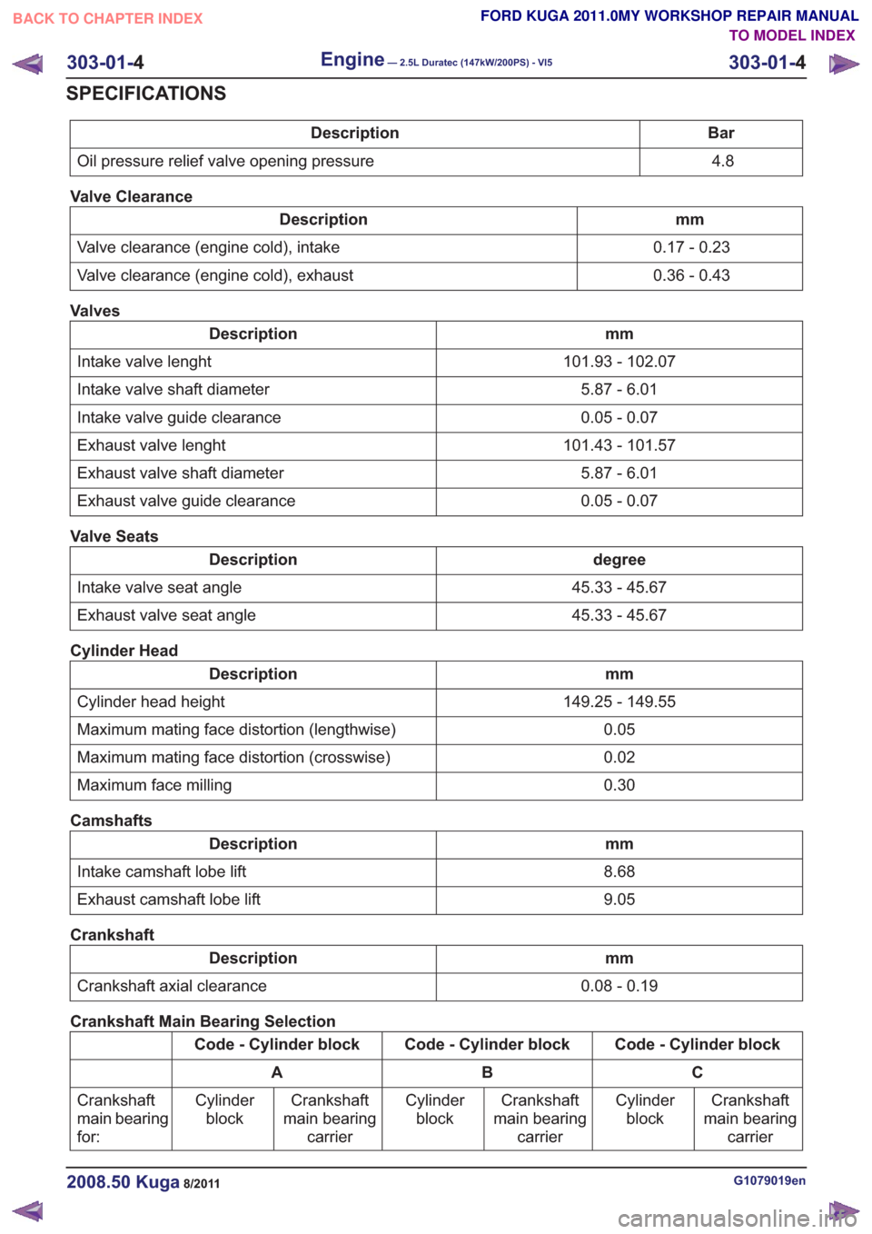
Bar
Description
4.8
Oil pressure relief valve opening pressure
Valve Clearance
mm
Description
0.17 - 0.23
Valve clearance (engine cold), intake
0.36 - 0.43
Valve clearance (engine cold), exhaust
Valves
mm
Description
101.93 - 102.07
Intake valve lenght
5.87 - 6.01
Intake valve shaft diameter
0.05 - 0.07
Intake valve guide clearance
101.43 - 101.57
Exhaust valve lenght
5.87 - 6.01
Exhaust valve shaft diameter
0.05 - 0.07
Exhaust valve guide clearance
Valve Seats
degree
Description
45.33 - 45.67
Intake valve seat angle
45.33 - 45.67
Exhaust valve seat angle
Cylinder Head
mm
Description
149.25 - 149.55
Cylinder head height
0.05
Maximum mating face distortion (lengthwise)
0.02
Maximum mating face distortion (crosswise)
0.30
Maximum face milling
Camshafts
mm
Description
8.68
Intake camshaft lobe lift
9.05
Exhaust camshaft lobe lift
Crankshaft
mm
Description
0.08 - 0.19
Crankshaft axial clearance
Crankshaft Main Bearing Selection
Code - Cylinder block
Code - Cylinder block
Code - Cylinder block
C
B
A
Crankshaft
main bearing carrier
Cylinder
block
Crankshaft
main bearing carrier
Cylinder
block
Crankshaft
main bearing carrier
Cylinder
block
Crankshaft
main bearing
for:
G1079019en2008.50 Kuga8/2011
303-01-
4
Engine— 2.5L Duratec (147kW/200PS) - VI5303-01-
4
SPECIFICATIONS
TO MODEL INDEX
BACK TO CHAPTER INDEX
FORD KUGA 2011.0MY WORKSHOP REPAIR MANUAL
Page 1542 of 2057
Engine – Overview
General
E62439
The 2.5L Duratec (VI5) engine is a turbo engine
with 5 cylinders and 20 valves, with electronically
controlled camshaft adjustment for both camshafts.The valve train is driven by a timing belt.
G1092773en2008.50 Kuga8/2011
303-01-
9
Engine— 2.5L Duratec (147kW/200PS) - VI5303-01-
9
DESCRIPTION AND OPERATION
TO MODEL INDEX
BACK TO CHAPTER INDEX
FORD KUGA 2011.0MY WORKSHOP REPAIR MANUAL
Page 1547 of 2057

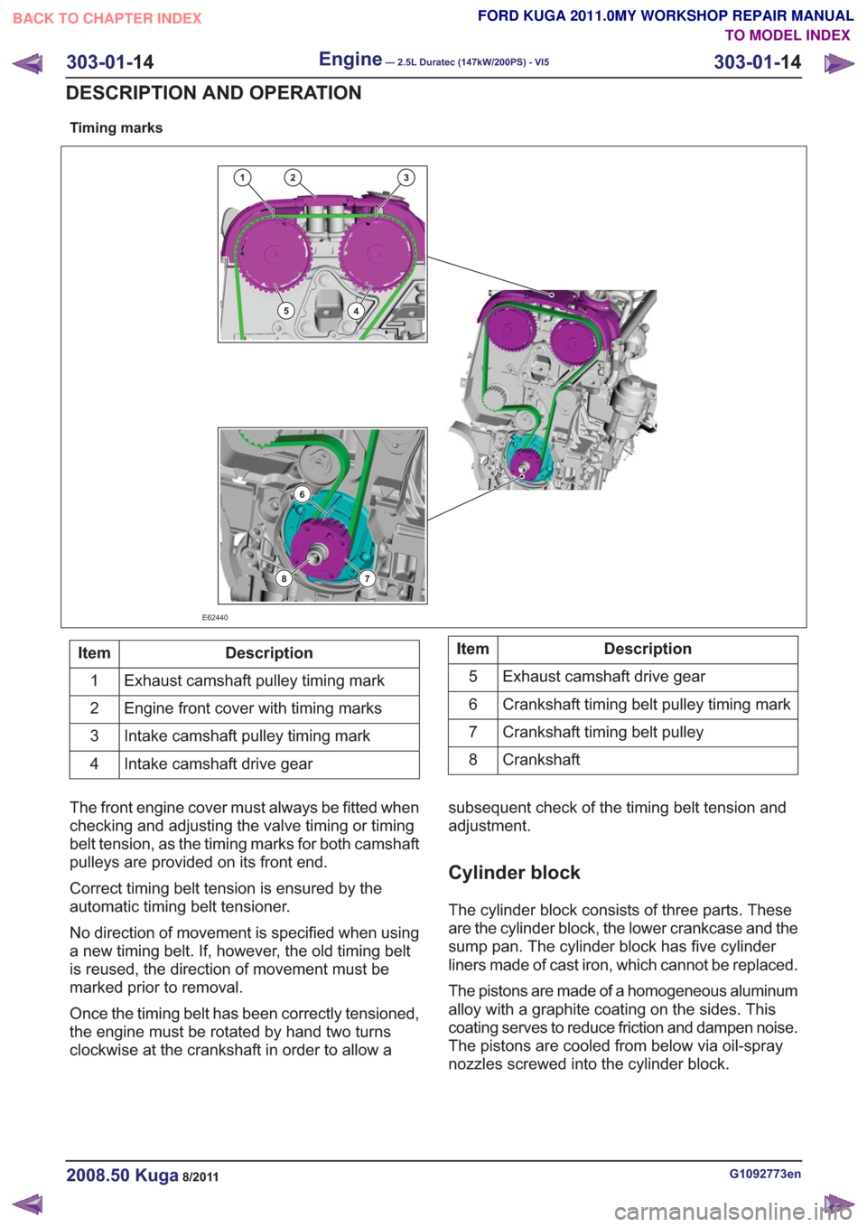
Timing marks
132
45
6
78
E62440
Description
Item
Exhaust camshaft pulley timing mark
1
Engine front cover with timing marks
2
Intake camshaft pulley timing mark
3
Intake camshaft drive gear
4Description
Item
Exhaust camshaft drive gear
5
Crankshaft timing belt pulley timing mark
6
Crankshaft timing belt pulley
7
Crankshaft
8
The front engine cover must always be fitted when
checking and adjusting the valve timing or timing
belt tension, as the timing marks for both camshaft
pulleys are provided on its front end.
Correct timing belt tension is ensured by the
automatic timing belt tensioner.
No direction of movement is specified when using
a new timing belt. If, however, the old timing belt
is reused, the direction of movement must be
marked prior to removal.
Once the timing belt has been correctly tensioned,
the engine must be rotated by hand two turns
clockwise at the crankshaft in order to allow a subsequent check of the timing belt tension and
adjustment.
Cylinder block
The cylinder block consists of three parts. These
are the cylinder block, the lower crankcase and the
sump pan. The cylinder block has five cylinder
liners made of cast iron, which cannot be replaced.
The pistons are made of a homogeneous aluminum
alloy with a graphite coating on the sides. This
coating serves to reduce friction and dampen noise.
The pistons are cooled from below via oil-spray
nozzles screwed into the cylinder block.
G1092773en2008.50 Kuga8/2011
303-01-
14
Engine— 2.5L Duratec (147kW/200PS) - VI5303-01-
14
DESCRIPTION AND OPERATION
TO MODEL INDEX
BACK TO CHAPTER INDEX
FORD KUGA 2011.0MY WORKSHOP REPAIR MANUAL
Page 1549 of 2057

Engine – System Operation and Component Description
System Operation
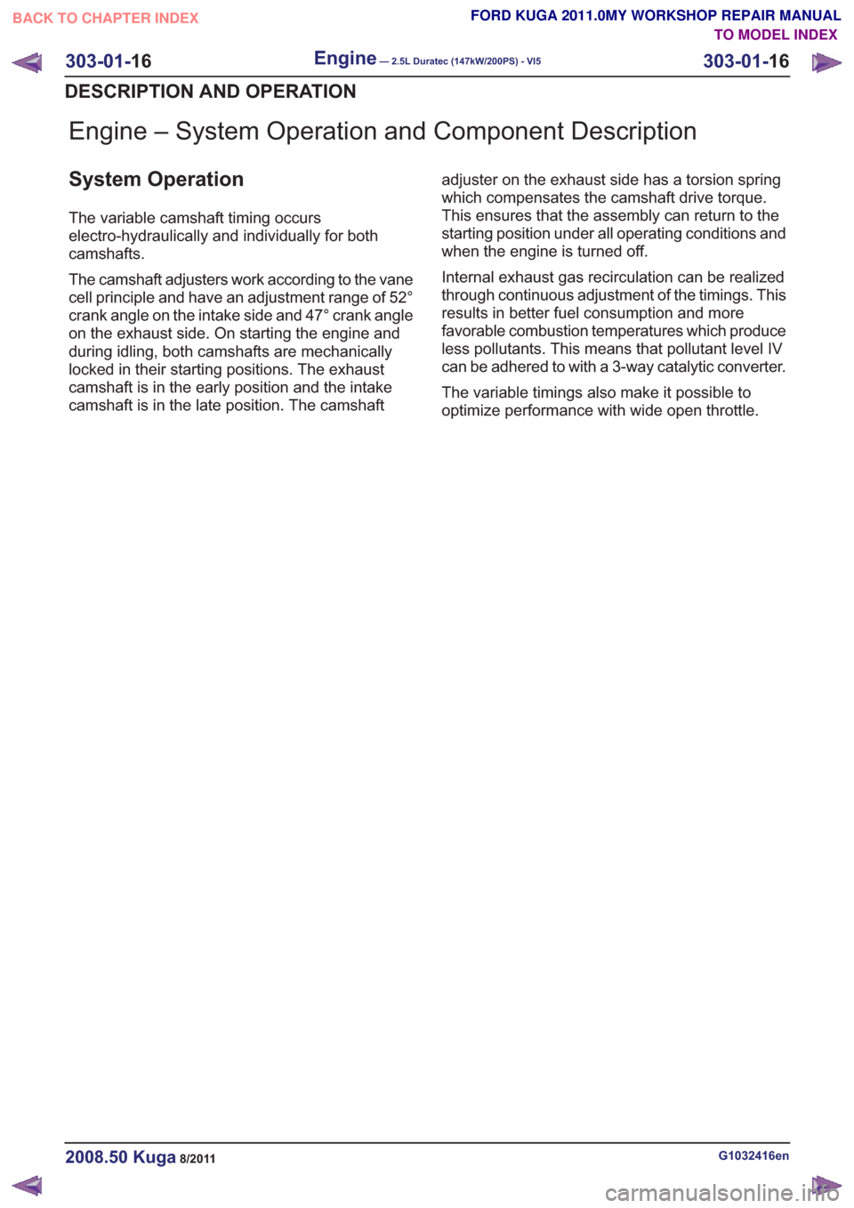
The variable camshaft timing occurs
electro-hydraulically and individually for both
camshafts.
The camshaft adjusters work according to the vane
cell principle and have an adjustment range of 52°
crank angle on the intake side and 47° crank angle
on the exhaust side. On starting the engine and
during idling, both camshafts are mechanically
locked in their starting positions. The exhaust
camshaft is in the early position and the intake
camshaft is in the late position. The camshaftadjuster on the exhaust side has a torsion spring
which compensates the camshaft drive torque.
This ensures that the assembly can return to the
starting position under all operating conditions and
when the engine is turned off.
Internal exhaust gas recirculation can be realized
through continuous adjustment of the timings. This
results in better fuel consumption and more
favorable combustion temperatures which produce
less pollutants. This means that pollutant level IV
can be adhered to with a 3-way catalytic converter.
The variable timings also make it possible to
optimize performance with wide open throttle.
G1032416en2008.50 Kuga8/2011
303-01-
16
Engine— 2.5L Duratec (147kW/200PS) - VI5303-01-
16
DESCRIPTION AND OPERATION
TO MODEL INDEX
BACK TO CHAPTER INDEX
FORD KUGA 2011.0MY WORKSHOP REPAIR MANUAL
Page 1550 of 2057
Variable camshaft timing
Timing retard
E62711
Description
Item
Camshaft pulley
1
Locking pin
2
Valve rotor
3
Rotor vane
4
Plunger
5Description
Item
Return spring
6
Camshaft adjuster solenoid
7
Duct connected to chamber (a)
A
Duct connected to chamber (b)
B
Oil feed duct
C
Oil return duct
Drive
G1032416en2008.50 Kuga8/2011
303-01- 17
Engine— 2.5L Duratec (147kW/200PS) - VI5303-01-
17
DESCRIPTION AND OPERATION
TO MODEL INDEX
BACK TO CHAPTER INDEX
FORD KUGA 2011.0MY WORKSHOP REPAIR MANUAL
Page 1553 of 2057
Intake Manifold(21 183 0)
Removal
NOTE:Removal steps in this procedure may
contain installation details.
1. Refer to: Fuel System Pressure Release
(310-00 Fuel System - General Information,
General Procedures).
2. Refer to: Battery Disconnect and Connect
(414-01 Battery, Mounting and Cables,
General Procedures).
3. Refer to: Air Cleaner (303-12 Intake Air
Distribution and Filtering - 2.5L Duratec
(147kW/200PS) - VI5, Removal and
Installation).
4.
E65070
5. CAUTION: Make sure that the inside of the pipe ends are clean and free of oil
residue.
1. Torque: 10Nm
2. Torque: 4Nm
3. Torque: 10Nm
2
1
3
E68504
6.
E67375
7.
E68413
8.Torque: 10Nm
E67741
G1079020en2008.50 Kuga8/2011
303-01- 20
Engine— 2.5L Duratec (147kW/200PS) - VI5303-01-
20
REMOVAL AND INSTALLATION
TO MODEL INDEX
BACK TO CHAPTER INDEX
FORD KUGA 2011.0MY WORKSHOP REPAIR MANUAL