2011 FORD KUGA reset
[x] Cancel search: resetPage 1822 of 2057
SECTION 307-01 Automatic Transmission/Transaxle
— Vehicles With: 5-Speed Automatic Transaxle - AW55 AWD
VEHICLE APPLICATION:2008.50 Kuga
PA G E
CONTENTS
SPECIFICATIONS
307-01-4
Specifications ........................................................................\
..............................................
DESCRIPTION AND OPERATION 307-01-5
Transmission Description (Component Location) ...............................................................
307-01-6
Transmission Description (Overview) ........................................................................\
.........
307-01-6
Components of the AW55 automatic transaxle ..................................................................
307-01-6
General overview ........................................................................\
....................................
307-01-8
Transaxle cooling ........................................................................\
....................................
307-01-8
External shift mechanism ........................................................................\
........................
307-01-9
Components of the electronic control ........................................................................\
.....
307-01-11
Overview of the brakes, clutches and one-way clutches ................................................
307-01-12
Input and output signals at the TCM ........................................................................\
.......
307-01-14
Knowing and Understanding Customer Concerns ..........................................................
307-01-14
Testing Possible Causes of Transmission Control Faults ...............................................
307-01-14
IDS Diagnosis ........................................................................\
.........................................
307-01-14
visual inspection ........................................................................\
.....................................
307-01-15
Towing the vehicle ........................................................................\
..................................
307-01-15
Push-starting the Vehicle ........................................................................\
........................
307-01-15
Jump-starting the Vehicle ........................................................................\
.......................
307-01-15
Selector Lever Emergency Release ........................................................................\
.......
307-01-16
Adjusting the Selector Lever Cable ........................................................................\
........
307-01-17
Transmission Fluid Level Check ........................................................................\
.............
307-01-17
Changing the Transmission Fluid ........................................................................\
...........
307-01-18
Diagnosis with IDS ........................................................................\
..................................
307-01-19
Resetting the counter for fluid change intervals. .............................................................
307-01-19
Programming the 'N' position of the TR sensor..............................................................
307-01-19
Resetting the values learned by the TCM .......................................................................
307-01-21
Transmission Description (System Operation and Component Description) .....................
307-01-21
System Operation ........................................................................\
.......................................
307-01-22
Functionality overview ........................................................................\
............................
307-01-24
Electronic Control System ........................................................................\
......................
307-01-24
Hydraulic Control System ........................................................................\
.......................
307-01-24
Type plate ........................................................................\
...............................................
307-01-25
Serial number of the transmission ........................................................................\
..........
307-01-25
Markings on the TCM ........................................................................\
.............................
307-01-25
Serial
number of the TCM ........................................................................\
.......................
307-01-25
Transmission Control ........................................................................\
..............................
307-01-27
Pin assignment for TCM connector 'C' (connection to transaxle) ...................................
307-01-28
Operation ........................................................................\
................................................
307-01-29
Gearshift control ........................................................................\
......................................
307-01-29
Adaptation ........................................................................\
...............................................
307-01-29
Shifting from 'P' to another transmission range ..............................................................
307-01-1
Automatic Transmission/Transaxle
— Vehicles With:
5-Speed Automatic Transaxle - AW55 AWD
307-01- 1
.
TO MODEL INDEX
BACK TO CHAPTER INDEX
PAGE 1 OF 3 FORD KUGA 2011.0MY WORKSHOP REPAIR MANUAL
Page 1823 of 2057
307-01-29
Automatic transmission, selector lever in position "D". ...................................................
307-01-29
Sport mode, selector lever in position "S" .......................................................................
307-01-29
Changing gear in select-shift mode........................................................................\
........
307-01-30
Selector lever from 'N' to 'R' position ........................................................................\
......
307-01-30
Self-test and Diagnosis ........................................................................\
...........................
307-01-30
Temperature controlled torque converter lockup ............................................................
307-01-30
Slip locking ........................................................................\
..............................................
307-01-30
Hill climbing ........................................................................\
.............................................
307-01-31
Downhill driving ........................................................................\
.......................................
307-01-31
Hill-hold function ........................................................................\
.....................................
307-01-31
Altitude correction ........................................................................\
...................................
307-01-31
Selector lever lock ........................................................................\
..................................
307-01-31
Shifting from P into another transmission range .............................................................
307-01-31
Shifting from N into another transmission range .............................................................
307-01-31
Power flow through the transmission ........................................................................\
......
307-01-31
Clutches and brakes ........................................................................\
...............................
307-01-33
Position P (park) ........................................................................\
.....................................
307-01-34
Position N (neutral) ........................................................................\
.................................
307-01-35
Position D, 1st gear........................................................................\
................................
307-01-36
Position D, 2nd gear ........................................................................\
...............................
307-01-37
Position D, 3rd gear ........................................................................\
................................
307-01-38
Position D, 4th gear ........................................................................\
................................
307-01-39
Position D, 5th gear ........................................................................\
................................
307-01-40
Position R (reverse) ........................................................................\
................................
307-01-41
Service instructions ........................................................................\
.................................
307-01-41
Towing procedure ........................................................................\
...................................
307-01-42
Reset adaptation data ........................................................................\
.............................
307-01-42
Limp home mode ........................................................................\
....................................
307-01-42
Component Description ........................................................................\
..............................
Tasks of the electronic components ........................................................................\
........
307-01-44
Input signals ........................................................................\
............................................
307-01-45
Output signals ........................................................................\
.........................................
Control valve assembly ........................................................................\
...........................
Shift solenoids S1 - S5 ........................................................................\
...........................
PWM-
solenoid valve – TCC (SLU) ........................................................................\
........
PWM solenoid valve – shift pressure (SLS) ...................................................................
PWM solenoid valve for main line pressure (SLT) ..........................................................
307-01-52
Installation position ........................................................................\
.................................
Operation ........................................................................\
................................................
Selector lever with integrated select-shift switch module ...............................................
Oil pump ........................................................................\
..................................................
Torque converter with TCC ........................................................................\
.....................
The TSS sensor ........................................................................\
......................................
The OSS sensor ........................................................................\
.....................................
The TFT sensor ........................................................................\
......................................
The TR sensor ........................................................................\
........................................
GENERAL PROCEDURES
T ransmission Fluid Level Check ........................................................................\
.................
307-01-63
T ransmission Fluid Drain and Refill ........................................................................\
............
REMOVAL AND INSTALLATION 307-01-67
Halfshaft Seal LH ........................................................................\
........................................
307-01-68
Halfshaft Seal RH........................................................................\
.......................................
307-01-69
Main Control Valve Body ........................................................................\
............................
307-01-2
Automatic Transmission/Transaxle
— Vehicles With:
5-Speed Automatic Transaxle - AW55 AWD
307-01- 2
.
TO MODEL INDEX
BACK TO CHAPTER INDEX
307-01-42
307-01-49
307-01-52 307-01-47
307-01-45
307-01-50
307-01-51
307-01-53
307-01-55
307-01-54
307-01-56
307-01-57
307-01-58
307-01-61 307-01-60
PAGE 2 OF 3 FORD KUGA 2011.0MY WORKSHOP REPAIR MANUAL
Page 1839 of 2057
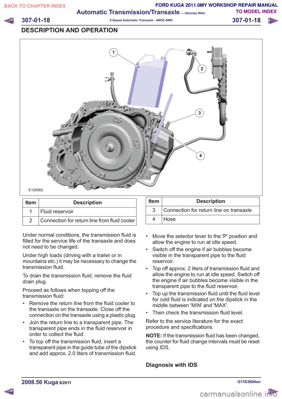
E126062
2
1
3
4
Description
Item
Fluid reservoir
1
Connection for return line from fluid cooler
2Description
Item
Connection for return line on transaxle
3
Hose
4
Under normal conditions, the transmission fluid is
filled for the service life of the transaxle and does
not need to be changed.
Under high loads (driving with a trailer or in
mountains etc.) it may be necessary to change the
transmission fluid.
To drain the transmission fluid, remove the fluid
drain plug.
Proceed as follows when topping off the
transmission fluid:
• Remove the return line from the fluid cooler to the transaxle on the transaxle. Close off the
connection on the transaxle using a plastic plug.
• Join the return line to a transparent pipe. The transparent pipe ends in the fluid reservoir in
order to collect the fluid.
• To top off the transmission fluid, insert a transparent pipe in the guide tube of the dipstick
and add approx. 2.0 liters of transmission fluid. • Move the selector lever to the 'P' position and
allow the engine to run at idle speed.
• Switch off the engine if air bubbles become visible in the transparent pipe to the fluid
reservoir.
• Top off approx. 2 liters of transmission fluid and allow the engine to run at idle speed. Switch off
the engine if air bubbles become visible in the
transparent pipe to the fluid reservoir.
• Top up the transmission fluid until the fluid level for cold fluid is indicated on the dipstick in the
middle between 'MIN' and 'MAX'.
• Then check the transmission fluid level.
Refer to the service literature for the exact
procedure and specifications.
NOTE: If the transmission fluid has been changed,
the counter for fluid change intervals must be reset
using IDS.
Diagnosis with IDS
G1163604en2008.50 Kuga8/2011
307-01- 18
Automatic Transmission/Transaxle
— Vehicles With:
5-Speed Automatic Transaxle - AW55 AWD
307-01- 18
DESCRIPTION AND OPERATION
TO MODEL INDEX
BACK TO CHAPTER INDEX
FORD KUGA 2011.0MY WORKSHOP REPAIR MANUAL
Page 1840 of 2057
E77584
NOTE:Due to static charging, measurements
inside the transaxle using a multimeter are
prohibited.
Stored DTCs in the engine management system
may affect transmission control. As a result, faults
in the transmission control system and engine
management system must be rectified in
accordance with the symptom-based diagnosis in
FordEtis IDS.
Applications of IDS Standard include:
• Resetting the counter for fluid change intervals.
• Programming the selector lever position 'N'.
• Resetting the values learned by the TCM.
Resetting the counter for fluid change
intervals.
This function must be performed if the transmission
fluid has been changed or a new automatic
transaxle has been installed with the previous TCM.
This function resets the values stored for the
pollution level of the transmission fluid.
Programming the 'N' position of the TR
sensor
This function must be executed if
• the TCM with integrated TR sensor is renewed,
• a new automatic transaxle is installed with the previous TCM.
• the selector lever cable or the selector mechanism assembly is renewed
• TR have been set due to a fault in the selector lever assembly or in the DTC (diagnostic trouble
code) sensor.
The TCM learns and stores the voltage value in
the 'N' position when this function is executed.
Resetting the values learned by the TCM
This function must be executed if
• a new automatic transaxle is installed with the previous TCM.
• a component of the automatic transaxle has been renewed.
G1163604en2008.50 Kuga8/2011
307-01- 19
Automatic Transmission/Transaxle
— Vehicles With:
5-Speed Automatic Transaxle - AW55 AWD
307-01- 19
DESCRIPTION AND OPERATION
TO MODEL INDEX
BACK TO CHAPTER INDEX
FORD KUGA 2011.0MY WORKSHOP REPAIR MANUAL
Page 1841 of 2057
The learned values are reset. Resetting the learned
values can briefly impair shifting quality until the
TCM has learned and stored the new values.
G1163604en2008.50 Kuga8/2011
307-01-20
Automatic Transmission/Transaxle
— Vehicles With:
5-Speed Automatic Transaxle - AW55 AWD
307-01- 20
DESCRIPTION AND OPERATION
TO MODEL INDEX
BACK TO CHAPTER INDEX
FORD KUGA 2011.0MY WORKSHOP REPAIR MANUAL
Page 1850 of 2057
To exactly determine the activation points of the
gear shifts and torque converter lockup on the
basis of the type of driving mode chosen, the TCM
receives the following information:
• Selected transmission range (TR sensor)
• Selected driving mode (normal/sport/select-shift)
• Transmission input shaft speed (TSS sensor)
• Transmission output shaft speed (OSS sensor)
• Transmission fluid temperature (TFT sensor)
• The engine speed and the torque as well as thethrottle plate opening - from the PCM via the
CAN databus
• Actuation of accelerator – from the PCM via the CAN databus
• The coolant temperature – from the PCM via the CAN databus
• Road speed – from the ABS module via the CAN databus
• Actuation of brake pedal – from the PCM via the CAN databus
Gearshift control
Adaptation
The TCM monitors every shift operation in all
driving conditions to make even and smooth gear
shifts possible. This is done by the control module,
which either lowers or increases the hydraulic line
pressure during gearshifts.
The changed pressure values are stored in the
control module memory after the engine is switched
off and retrieved during engine starting. This
improves the shift comfort and extends the service
life.
Full adaptability occurs when the following criteria
are met:
• Throttle plate opening is constant.
• Transmission fluid temperature between 65 °Cand 110 °C.
Shifting from 'P' to another transmission
range
To be able to move the selector lever from 'P' into
another transmission range, the ignition must be
switched on and the brake pedal pressed (stoplamp
switch on). The TCM detects the position of the
brake pedal via the CAN data bus and the engaged
transmission range from the TR sensor. Based on this information, the TCM transmits a
signal to the select-shift switch module. This
activates the brake shift interlock actuator in the
selector lever assembly.
When the brake shift interlock actuator is activated,
the locking pin is retracted so that another
transmission range can be selected.
The brake shift interlock actuator is deactivated
when the ignition is switched off. It is mechanically
locked when the gear selector lever is in 'P'.
Automatic transmission, selector lever in
position "D".
The TCM adapts the shift points to match the
driving conditions. Normally the TCM is in adaptive
mode and gear changes take place adapted to the
driving conditions. If special driving conditions are
detected, the TCM switches to predefined
characteristics.
When driving with normal acceleration, the TCM
uses a preset shift program which is optimized for
economical driving.
This shift program is suitable for "normal" driving
and delivers early upward changes and torque
converter lockup. Furthermore, the transmission
fluid pressure is adapted to make smooth
engagement of the gears possible.
Sport mode, selector lever in position "S"
The transmission switches from automatic
operation into sport mode. In this mode the TCM
switches to another set of characteristic curves.
These characteristic curves for control of the gear
changes are adapted to sporting calculations (e.g.
gear change at higher engine speed).
In the sport mode shift program the shift points are
set so that good performance is offered. Changing
down occurs at lower engine speeds.
Manual gear changes (select-shift mode) can be
made in sport mode by moving the selector lever
in the (+) or (-) direction.
Changing gear in select-shift mode
If you move the selector lever to 'S', the automatic
transaxle remains hydraulically in 'D' position. If
you move the gear selector lever forwards (-), the
G1163605en2008.50 Kuga8/2011
307-01-
29
Automatic Transmission/Transaxle
— Vehicles With:
5-Speed Automatic Transaxle - AW55 AWD
307-01- 29
DESCRIPTION AND OPERATION
TO MODEL INDEX
BACK TO CHAPTER INDEX
FORD KUGA 2011.0MY WORKSHOP REPAIR MANUAL
Page 1863 of 2057
Reset adaptation data
Adaptation values are stored in the software of the
TCM:
• Adaptation should be reset after an internalcomponent has been exchanged or the whole
transmission has been changed.
The adaptation of the transmission is reset via IDS.
Limp home mode
The TCM software contains functions which take
control of the transmission if serious faults occur.
The fault characteristic decides which strategies
are to be used.
The vehicle remains capable of restricted
operation.
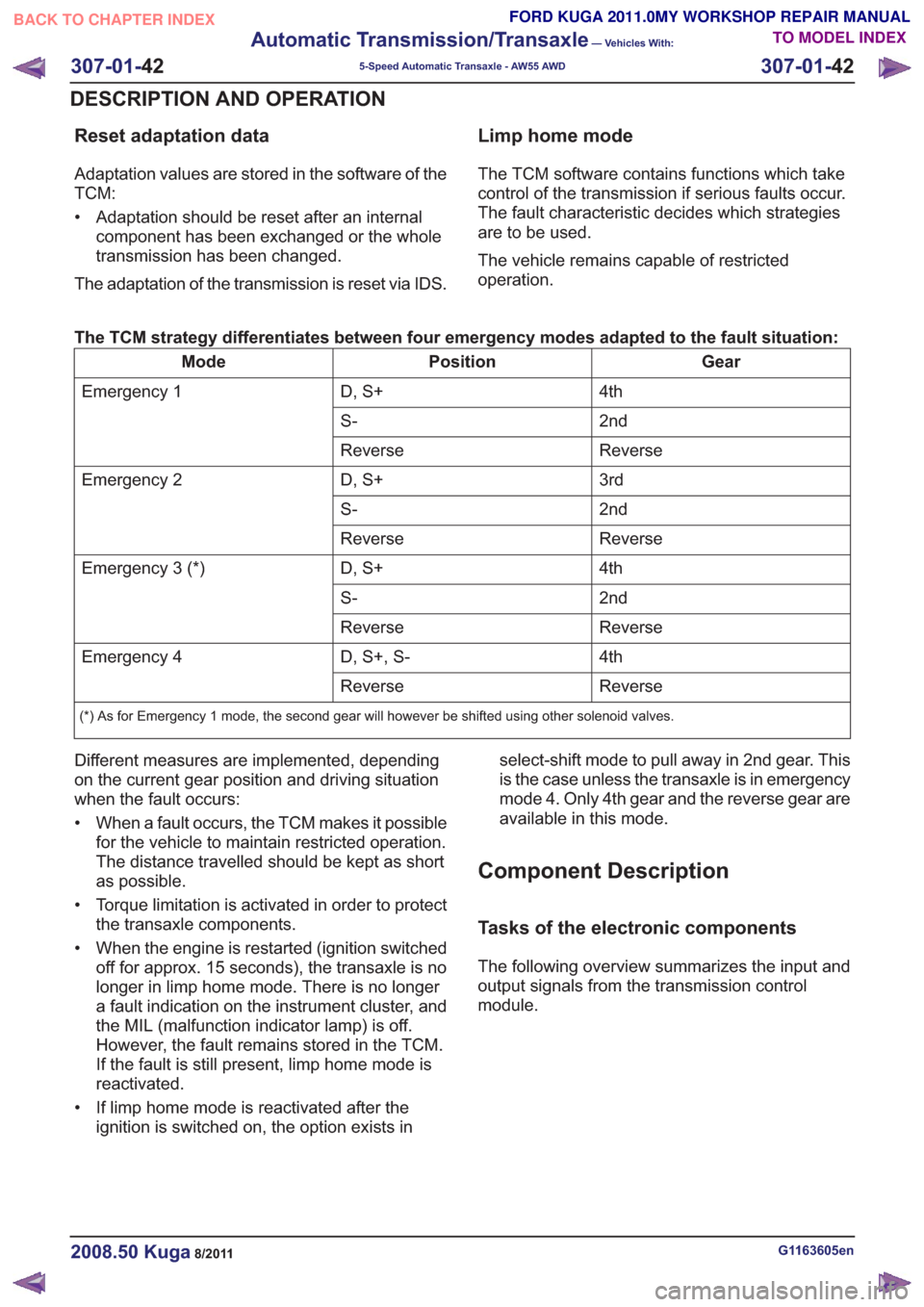
The TCM strategy differentiates between four emergency modes adapted to the fault situation:
Gear
Position
Mode
4th
D, S+
Emergency 1
2nd
S-
Reverse
Reverse
3rd
D, S+
Emergency 2
2nd
S-
Reverse
Reverse
4th
D, S+
Emergency 3 (*)
2nd
S-
Reverse
Reverse
4th
D, S+, S-
Emergency 4
Reverse
Reverse
(*) As for Emergency 1 mode, the second gear will however be shifted using other solenoid valves.
Different measures are implemented, depending
on the current gear position and driving situation
when the fault occurs:
• When a fault occurs, the TCM makes it possible
for the vehicle to maintain restricted operation.
The distance travelled should be kept as short
as possible.
• Torque limitation is activated in order to protect the transaxle components.
• When the engine is restarted (ignition switched off for approx. 15 seconds), the transaxle is no
longer in limp home mode. There is no longer
a fault indication on the instrument cluster, and
the MIL (malfunction indicator lamp) is off.
However, the fault remains stored in the TCM.
If the fault is still present, limp home mode is
reactivated.
• If limp home mode is reactivated after the ignition is switched on, the option exists in select-shift mode to pull away in 2nd gear. This
is the case unless the transaxle is in emergency
mode 4. Only 4th gear and the reverse gear are
available in this mode.
Component Description
Tasks of the electronic components
The following overview summarizes the input and
output signals from the transmission control
module.
G1163605en2008.50 Kuga8/2011
307-01-
42
Automatic Transmission/Transaxle
— Vehicles With:
5-Speed Automatic Transaxle - AW55 AWD
307-01- 42
DESCRIPTION AND OPERATION
TO MODEL INDEX
BACK TO CHAPTER INDEX
FORD KUGA 2011.0MY WORKSHOP REPAIR MANUAL