2011 FORD KUGA pressure
[x] Cancel search: pressurePage 204 of 2057

Parking Aid – Overview
Parking aid sensors
CAUTIONS:
Always keep sensors free from dirt, ice and
snow. Do not use any sharp objects to
clean the sensors. If a high-pressure cleaner is used to wash
the vehicle, the jet must only be aimed at
the sensors briefly at a distance of at least
20 cm.
The parking aid sensors have a separate
decoupling ring, which must be removed before
painting the sensors, and then refitted.
Front sensors detection range G1034398en
2008.50 Kuga 8/2011 413-13-5
Parking Aid
413-13-5
DESCRIPTION AND OPERATIONTO MODEL INDEX
BACK TO CHAPTER INDEX
FORD KUGA 2011.0MY WORKSHOP REPAIR MANUAL600800mmE97414
Page 205 of 2057

Rear sensors detection range
Parking aid camera module
It is not necessary to programme the module after
changing it.
Parking Aid Camera
CAUTIONS:
Always keep the reversing camera free
from dirt, ice and snow. Do not clean with
sharp objects, fat solvents, wax or organic
media. Only use a damp cloth for cleaning.
If a high-pressure cleaner is used to wash
the vehicle, the jet must only be aimed at
the reversing camera briefly at a distance
of at least 20 cm.
The reversing camera is sensitive to
pressure. The position and angle of the
camera can be changed with increased
pressure.
It is not necessary to programme the camera after
changing it. G1034398en
2008.50 Kuga 8/2011 413-13-6
Parking Aid
413-13-6
DESCRIPTION AND OPERATIONTO MODEL INDEX
BACK TO CHAPTER INDEX
FORD KUGA 2011.0MY WORKSHOP REPAIR MANUAL6001800mmE97415
Page 214 of 2057

Component Description
Rear parking aid speaker
The rear parking aid speaker, in addition to its
actual function, is also used for audible indication
of various types of error in the front and rear
parking aids. If the rear parking aid speaker
becomes defective, the front parking aid speaker
will then be used to indicate failure modes.
If an error is detected in the system, a signal tone
is emitted via the speaker for 3 seconds.
Parking aid sensors
CAUTIONS:
Always keep sensors free from dirt, ice and
snow. Do not use any sharp objects to
clean the sensors.
If a high-pressure cleaner is used to wash
the vehicle, the jet must only be aimed at
the sensors briefly at a distance of at least
20 cm.
The parking aid sensor consists of the following:
• Plastic housing
• Aluminum membrane with Piezo disc
• Decoupling ring
• Printed circuit board (PCB)
The parking aid sensor consists of a sensor and a
holder. The holder makes sure that each parking
aid sensor is correctly orientated in relation to its
location in the rear bumper.
The sensors have a 3-pin connector which is
connected to the wiring harness of the front
bumper. This in turn is connected to the main body
wiring harness. Three pins provide for power
supply, ground and signal lines to and from the
parking aid module. The disc resonates at a frequency of ca. 50kHz,
producing the ultrasonic output. The disc also
receives the reflected echo signal from any objects
within range.
Parking aid module
The parking aid module has three connectors which
provide for power, ground and MS CAN bus
connections, as well as the front and rear parking
aid sensors, the parking aid switch and parking aid
speaker.
The parking aid module carries out self-check
routines and when the parking aid is active, checks
the parking aid sensor wiring for short or open
circuits. If a concern is detected, a diagnostic
trouble code (DTC) is stored in a memory in the
parking aid module and the front and rear parking
aid sensors will be disabled until the DTC is cleared
and the ignition cycled. The driver recognizes a
problem through the flashing LED and a shrill
continuous tone, which is emitted for 3 seconds
when the parking aid is activated. If the parking aid
is working properly, short tones are emitted instead
of this continuous tone. DTCs can be read using
the Ford approved diagnostic tool through the data
link connector (DLC).
G1034399en
2008.50 Kuga 8/2011 413-13-15
Parking Aid
413-13-15
DESCRIPTION AND OPERATIONTO MODEL INDEX
BACK TO CHAPTER INDEX
FORD KUGA 2011.0MY WORKSHOP REPAIR MANUALE89773 E89772
Page 363 of 2057

Front Fog Lamp Adjustment
General Equipment
Headlamp Beam Setter
Activation
1. Place the vehicle on a level surface.
2. Ensure that the tire pressures are to
specification and that the vehicle is not
overloaded.
3. Switch on the front fog lamps.
4. Set the measuring screen of the beam setting
equipment to the correct front fog lamp
adjustment setting.
Refer to: Specifications (417-01 Exterior
Lighting, Specifications).
General Equipment: Headlamp Beam Setter
5. Adjust the fog lamp so that the cut-off line
touches the horizontal line. G1066056en
2008.50 Kuga 8/2011 417-01-29
Exterior Lighting
417-01-29
GENERAL PROCEDURESTO MODEL INDEX
BACK TO CHAPTER INDEX
FORD KUGA 2011.0MY WORKSHOP REPAIR MANUALE11721815
Page 364 of 2057

Headlamp Adjustment
General Equipment
Headlamp Beam Setter
All Vehicles
1. NOTE: Make sure that the tire pressures are to
specification and that the vehicle is unladen.
NOTE: Only use a damp cloth to clean the
headlamp lens to avoid any electrostatic
charging.
Ensure that the adjustment is made with the
suspension set up.
2. Place the vehicle on a level surface.
Vehicles with conventional headlamps
3. Repeatedly operate the headlamp leveling
switch and then set it to "0".
Vehicles with adaptive front lighting
4. Use the diagnostic tool to make certain that the
front wheels are in the straight ahead position.
Vehicles with gas discharge headlamps
5. Calibrate the headlamp leveling system using
the diagnostic tool.
All Vehicles
6. NOTE: Always follow the manufacturer's
instructions when handling the equipment.
Set the measuring screen of the beam setting
equipment to the correct headlamp adjustment
setting.
Refer to: Specifications (417-01 Exterior
Lighting, Specifications).
General Equipment: Headlamp Beam Setter
7. Switch on dipped beam. 8.
Adjust the dipped beams so that the light/dark
boundary touches the horizontal line. 9. NOTE:
It is acceptable for a stray portion of the
low beam to cross the 15° line.
Adjust the headlamps so that the rising line of
the boundary line lies at the intersection of G1066055en
2008.50 Kuga 8/2011 417-01-30
Exterior Lighting
417-01-30
GENERAL PROCEDURESTO MODEL INDEX
BACK TO CHAPTER INDEX
FORD KUGA 2011.0MY WORKSHOP REPAIR MANUALE11721715
Page 389 of 2057

Programmable Module Installation
Activation
5.
Install the most up-to-date software version in
IDS.
6. If, before replacing a module, it was not possible
to read out the vehicle-specific data using the
integrated diagnostic system (IDS) (the module
to be replaced does not respond) then, during
programming of the new module, the
vehicle-specific data must be entered manually
via a selection list in IDS or via a code which
can be obtained from the Technical Hotline.
7. In order to program, select the "Install
programmable module" submenu in the "Module
programming" menu tool box and then follow
the instructions.
8. The following modules must be programmed
after replacement:
•
• Anti-lock braking system module (ABS)
• Audio system module (ACM)
• CD player (CDP)
• Driver's door control unit (D-DCU)
• Passenger's door control unit (P-DCU)
• Rear left door control unit (RL-DCU)
• Rear right door control unit (RR-DCU)
• Electrical power steering (EPS)
• Generic Display Module (GDM) (vehicles
with DVD navigation system with
touchscreen)
• Generic electronic module (GEM)
• Headlamp control module (HCM) (vehicles with gas discharge headlamps)
• Instrument cluster (IC)
• Navigation system (NAV) (vehicles with navigation system)
• Parking aid module(PAM)
• Powertrain control module (PCM)
• Restraint control module (RCM)
• Rear entertainment system module (RETM) (vehicles with rear seat entertainment
system)
9. In order to configure the PCM, select the
"Programmable parameters" submenu in the
"Module programming" menu tool box and then
follow the instructions.
10. For vehicles with anti-lock braking system and
electronic stability program, these must also be configured using IDS following replacement of
the lateral acceleration sensor, yaw rate sensor
or pressure sensor. Configuration is performed
in the "Programmable parameters" menu tool
box.
G1158258en
2008.50 Kuga 8/2011 418-01-3
Module Configuration
418-01-3
GENERAL PROCEDURESTO MODEL INDEX
BACK TO CHAPTER INDEX
FORD KUGA 2011.0MY WORKSHOP REPAIR MANUAL
Page 1228 of 2057

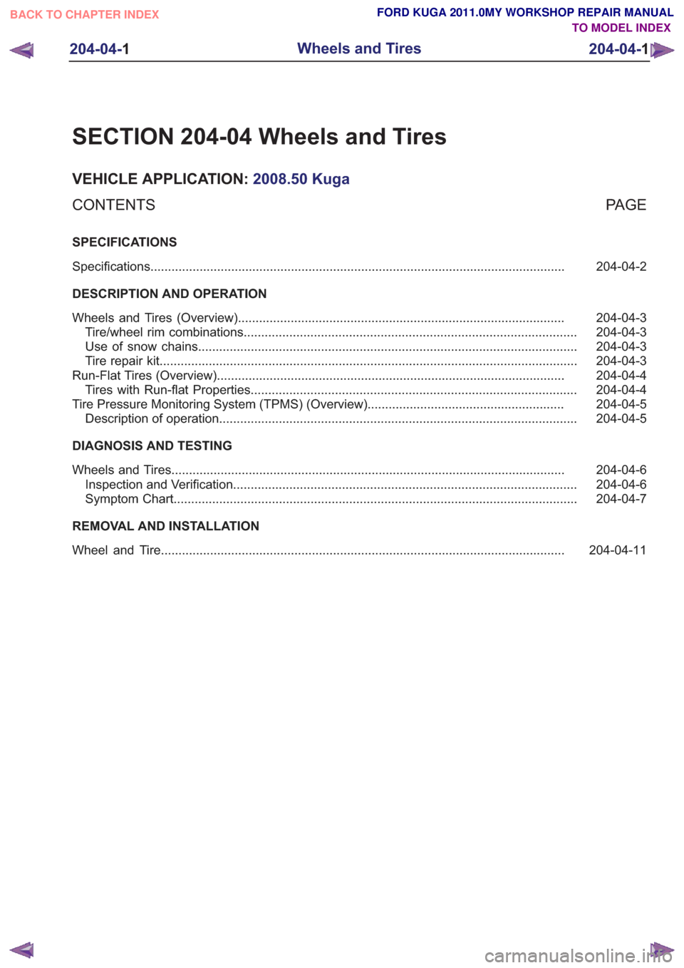
SECTION 204-04 Wheels and Tires
VEHICLE APPLICATION:2008.50 Kuga
PA G E
CONTENTS
SPECIFICATIONS
204-04-2
Specifications ........................................................................\
..............................................
DESCRIPTION AND OPERATION 204-04-3
Wheels and Tires (Overview) ........................................................................\
.....................
204-04-3
Tire/wheel rim combinations ........................................................................\
.......................
204-04-3
Use of snow chains ........................................................................\
....................................
204-04-3
Tire repair kit ........................................................................\
...............................................
204-04-4
Run-Flat Tires (Overview) ........................................................................\
...........................
204-04-4
Tires with Run-flat Properties ........................................................................\
.....................
204-04-5
Tire Pressure Monitoring System (TPMS) (Overview) ........................................................
204-04-5
Description of operation ........................................................................\
..............................
DIAGNOSIS AND TESTING 204-04-6
Wheels and Tires ........................................................................\
........................................
204-04-6
Inspection and Verification ........................................................................\
..........................
204-04-7
Symptom Chart ........................................................................\
...........................................
REMOVAL AND INSTALLATION 204-04-11
Wheel and Tire........................................................................\
...........................................
204-04- 1
Wheels and Tires
204-04- 1
.
TO MODEL INDEX
BACK TO CHAPTER INDEX
FORD KUGA 2011.0MY WORKSHOP REPAIR MANUAL
Page 1229 of 2057

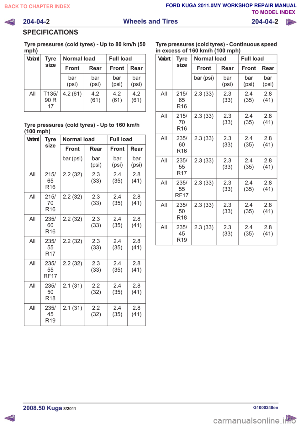
Tyre pressures (cold tyres) - Up to 80 km/h (50
mph)
Full load
Normal load
Tyre
size
Variant
Rear
Front
Rear
Front
bar
(psi)
bar
(psi)
bar
(psi)
bar
(psi)
4.2
(61)
4.2
(61)
4.2
(61)
4.2 (61)
T135/
90 R 17
All
Tyre pressures (cold tyres) - Up to 160 km/h
(100 mph)
Full load
Normal load
Tyre
size
Variant
Rear
Front
Rear
Front
bar
(psi)
bar
(psi)
bar
(psi)
bar (psi)
2.8
(41)
2.4
(35)
2.3
(33)
2.2 (32)
215/
65
R16
All
2.8
(41)
2.4
(35)
2.3
(33)
2.2 (32)
215/
70
R16
All
2.8
(41)
2.4
(35)
2.3
(33)
2.2 (32)
235/
60
R16
All
2.8
(41)
2.4
(35)
2.3
(33)
2.2 (32)
235/
55
R17
All
2.8
(41)
2.4
(35)
2.3
(33)
2.2 (32)
235/
55
RF17
All
2.8
(41)
2.4
(35)
2.2
(32)
2.1 (31)
235/
50
R18
All
2.8
(41)
2.4
(35)
2.2
(32)
2.1 (31)
235/
45
R19
All Tyre pressures (cold tyres) - Continuous speed
in excess of 160 km/h (100 mph)
Full load
Normal load
Tyre
size
Variant
Rear
Front
Rear
Front
bar
(psi)
bar
(psi)
bar
(psi)
bar (psi)
2.8
(41)
2.4
(35)
2.3
(33)
2.3 (33)
215/
65
R16
All
2.8
(41)
2.4
(35)
2.3
(33)
2.3 (33)
215/
70
R16
All
2.8
(41)
2.4
(35)
2.3
(33)
2.3 (33)
235/
60
R16
All
2.8
(41)
2.4
(35)
2.3
(33)
2.3 (33)
235/
55
R17
All
2.8
(41)
2.4
(35)
2.3
(33)
2.3 (33)
235/
55
RF17
All
2.8
(41)
2.4
(35)
2.3
(33)
2.3 (33)
235/
50
R18
All
2.8
(41)
2.4
(35)
2.3
(33)
2.3 (33)
235/
45
R19
All
G1000248en2008.50 Kuga8/2011
204-04-
2
Wheels and Tires
204-04- 2
SPECIFICATIONS
TO MODEL INDEX
BACK TO CHAPTER INDEX
FORD KUGA 2011.0MY WORKSHOP REPAIR MANUAL