2011 FORD KUGA fuel line
[x] Cancel search: fuel linePage 1723 of 2057
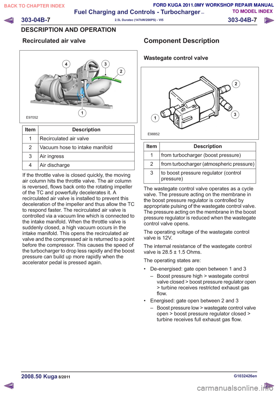
Recirculated air valve
E97052
43
2
1
Description
Item
Recirculated air valve
1
Vacuum hose to intake manifold
2
Air ingress
3
Air discharge
4
If the throttle valve is closed quickly, the moving
air column hits the throttle valve. The air column
is reversed, flows back onto the rotating impeller
of the TC and powerfully decelerates it. A
recirculated air valve is installed to prevent this
deceleration of the impeller and thus allow the TC
to respond faster. The recirculated air valve is
controlled via a vacuum line which is connected to
the intake manifold. When the throttle valve is
suddenly closed, a high vacuum occurs in the
intake manifold. This opens the recirculated air
valve and the compressed air is returned to a point
before the compressor. This causes the speed of
the turbocharger to drop less rapidly and the boost
pressure can build up more rapidly when the
accelerator pedal is pressed again.
Component Description
Wastegate control valve
1
2
3
E98852
Description
Item
from turbocharger (boost pressure)
1
from turbocharger (atmospheric pressure)
2
to boost pressure regulator (control
pressure)
3
The wastegate control valve operates as a cycle
valve. The pressure acting on the membrane in
the boost pressure regulator is controlled by
appropriate pulsing of the wastegate control valve.
The pressure acting on the membrane in the boost
pressure regulator is reduced when the wastegate
control valve opens.
The operating voltage of the wastegate control
valve is 12V.
The internal resistance of the wastegate control
valve is 28.5 ± 1.5 Ohms.
The operating states are:
• De-energised: gate open between 1 and 3 – Boost pressure high > wastegate controlvalve closed > boost pressure regulator open
> turbine receives restricted exhaust gas
flow.
• Energised: gate open between 2 and 3 – Boost pressure low > wastegate control valveopen > boost pressure regulator closed >
turbine receives full exhaust gas flow.
G1032426en2008.50 Kuga8/2011
303-04B- 7
Fuel Charging and Controls - Turbocharger
—
2.5L Duratec (147kW/200PS) - VI5
303-04B- 7
DESCRIPTION AND OPERATION
TO MODEL INDEX
BACK TO CHAPTER INDEX
FORD KUGA 2011.0MY WORKSHOP REPAIR MANUAL
Page 1726 of 2057
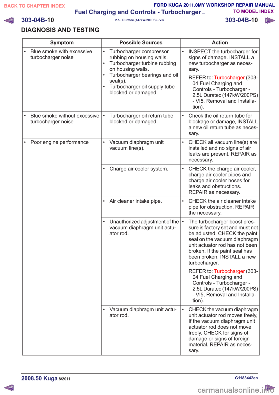
Action
Possible Sources
Symptom
• INSPECT the turbocharger forsigns of damage. INSTALL a
new turbocharger as neces-
sary.
REFER to: Turbocharger (303-
04 Fuel Charging and
Controls - Turbocharger -
2.5L Duratec (147kW/200PS)
- VI5, Removal and Installa-
tion).
• Turbocharger compressor
rubbing on housing walls.
• Turbocharger turbine rubbing on housing walls.
• Turbocharger bearings and oil seal(s).
• Turbocharger oil supply tube blocked or damaged.
• Blue smoke with excessive
turbocharger noise
• Check the oil return tube forblockage or damage, INSTALL
a new oil return tube as neces-
sary.
• Turbocharger oil return tube
blocked or damaged.
• Blue smoke without excessive
turbocharger noise
• CHECK all vacuum line(s) areinstalled and no signs of air
leaks are present. REPAIR as
necessary.
• Vacuum diaphragm unit
vacuum line(s).
• Poor engine performance
• CHECK the charge air cooler,charge air cooler pipes and
charge air cooler hoses for
leaks and obstructions.
REPAIR as necessary.
• Charge air cooler system.
• CHECK the air cleaner intakepipe for obstruction. REPAIR
the necessary.
• Air cleaner intake pipe.
• The turbocharger boost pres-sure is factory set and must not
be adjusted. CHECK the paint
seal on the vacuum diaphragm
unit actuator rod has not been
broken. If the paint seal has
been broken, INSTALL a new
turbocharger.
REFER to: Turbocharger (303-
04 Fuel Charging and
Controls - Turbocharger -
2.5L Duratec (147kW/200PS)
- VI5, Removal and Installa-
tion).
• Unauthorized adjustment of the
vacuum diaphragm unit actu-
ator rod.
• CHECK the vacuum diaphragmunit actuator rod moves freely,
If the vacuum diaphragm unit
actuator rod does not move
freely. CHECK for signs of
damage or signs of foreign
material. REPAIR as neces-
sary.
• Vacuum diaphragm unit actu-
ator rod.
G1183442en2008.50 Kuga8/2011
303-04B- 10
Fuel Charging and Controls - Turbocharger
—
2.5L Duratec (147kW/200PS) - VI5
303-04B- 10
DIAGNOSIS AND TESTING
TO MODEL INDEX
BACK TO CHAPTER INDEX
FORD KUGA 2011.0MY WORKSHOP REPAIR MANUAL
Page 1790 of 2057
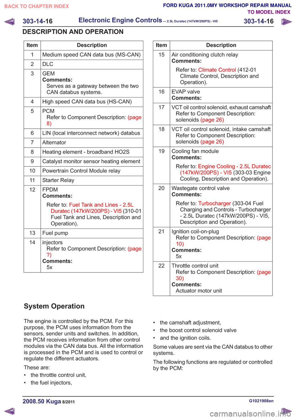
Description
Item
Medium speed CAN data bus (MS-CAN)
1
DLC
2
GEM
Comments:Serves as a gateway between the two
CAN databus systems.
3
High speed CAN data bus (HS-CAN)
4
PCMRefertoComponentDescription:(page
8)
5
LIN (local interconnect network) databus
6
Alternator
7
Heating element - broadband HO2S
8
Catalyst monitor sensor heating element
9
Powertrain Control Module relay
10
Starter Relay
11
FPDM
Comments:Refer to: Fuel Tank and Lines - 2.5L
Duratec (147kW/200PS) - VI5 (310-01
Fuel Tank and Lines, Description and
Operation).
12
Fuel pump
13
injectorsRefertoComponentDescription:(page
?)
Comments: 5x
14Description
Item
Air conditioning clutch relay
Comments:Refer to: Climate Control (412-01
Climate Control, Description and
Operation).
15
EVAP valve
Comments:
16
VCT oil control solenoid, exhaust camshaftRefer to Component Description:
solenoids(page26)
17
VCT oil control solenoid, intake camshaftRefer to Component Description:
solenoids(page26)
18
Cooling fan module
Comments:Refer to: Engine Cooling - 2.5L Duratec
(147kW/200PS) - VI5 (303-03 Engine
Cooling, Description and Operation).
19
Wastegate control valve
Comments:Refer to: Turbocharger (303-04 Fuel
Charging and Controls - Turbocharger
- 2.5L Duratec (147kW/200PS) - VI5,
Description and Operation).
20
Ignition coil-on-plugRefertoComponentDescription:(page
10)
Comments: 5x
21
Throttle control unitRefertoComponentDescription:(page
30)
Comments: Actuator motor unit
22
System Operation
The engine is controlled by the PCM. For this
purpose, the PCM uses information from the
sensors, sender units and switches. In addition,
the PCM receives information from other control
modules via the CAN data bus. All the information
is processed in the PCM and is used to control or
regulate the different actuators.
These are:
• the throttle control unit,
• the fuel injectors, • the camshaft adjustment,
• the boost control solenoid valve
• and the ignition coils.
Some values are sent via the CAN databus to other
systems.
The following functions are regulated or controlled
by the PCM:
G1021908en2008.50 Kuga8/2011
303-14-
16
Electronic Engine Controls— 2.5L Duratec (147kW/200PS) - VI5303-14-
16
DESCRIPTION AND OPERATION
TO MODEL INDEX
BACK TO CHAPTER INDEX
FORD KUGA 2011.0MY WORKSHOP REPAIR MANUAL
Page 1795 of 2057
actuated) or opened (actuated). Each cylinder has
its own injector. The injection is accurately dosed
and takes place at a time determined by the PCM.
Injection takes place immediately in front of the
intake valves of the cylinder. The injectors are
actuated ground side via end-stages integrated
into the PCM and using the signal calculated by
the engine management system. Power is supplied
via the Powertrain Control Module relay in the BJB.
The injected fuel quantity depends on the opening
time, the fuel pressure and the diameter of the
nozzle holes.
The fuel metering is determined via open or
closed-loop control.
The open control loop differs from the closed
control loop in that the lambda control is
deactivated.
The PCM switches from closed to open-loop control
if the HO2S cools down to below 600°C or fails, as
well as when accelerating, coasting and at full load.
Regulation of injected fuel quantity via the PCM
involves:
• controlling the fuel pump,
• calculating the required quantity of fuel forengine starting,
• observance of the desired air/fuel ratio,
• calculating air mass,
• and calculating the fuel quantity for the different operating states and corresponding fuel
adjustment measures.
Open loop control
Open loop control is used primarily for fuel
injection, as long as the signals of the HO2S are
not involved in the calculation of the PCM.
The two most important reasons that make it
absolutely essential to run the engine without
lambda control (open-loop control) are the following
operating conditions:
• Cold engine (starting, warm-up phase)
• Full-load operation (WOT (wide open throttle))
Under these operating conditions the engine needs
a rich air/fuel mixture with lambda values below λ
= 1 in order to achieve optimum running or
optimum performance.
It is possible to keep this unregulated range very
small by using a broadband HO2S.
Closed-loop control
Closed loop control ensures strict control of
exhaust emissions in conjunction with the TWC (three-way catalytic converter) and economical fuel
consumption. With closed loop control, the signals
from the HO2S are analyzed by the PCM and the
engine always runs in the optimum range of λ = 1.
In addition to the normal HO2S, the signal from the
monitoring sensor for the catalytic converter is also
included in the control. The lambda control is
optimized on the basis of this data.
Certain factors such as wear, component
tolerances or more minor defects such as air leaks
in the intake system are compensated for by
lambda control. If the deviation occurs for a longer
period of time, this is recorded by the adaptive
(self-learning) function of lambda control. In this
instance, the entire map is shifted by the
corresponding amount, to enable control to
commence once again from the virtual baseline.
These adaptive settings are stored in the PCM and
are also used in open-loop control conditions.
If the adaptive value is too high or too low, an error
is stored in the fault memory of the PCM.
Oxygen sensor (HO2S) and catalyst monitor
sensor
A broadband HO2S is used as the HO2S. The
HO2S is located in front of the TWC. The catalyst
monitor sensor is located in the center of the TWC
so that it can detect any deterioration in the
cleaning performance of the TWC more quickly.
The HO2S measures the residual amount of
oxygen in the exhaust before the TWC.
The catalyst monitor sensor measures the amount
of oxygen in the exhaust gas after or in the TWC.
Both the HO2S and the catalyst monitor sensor
transmit these data to the PCM.
The broadband HO2S works at temperatures of
between 650°C and 900 °C. If the temperature
rises above 1000°C, the oxygen sensor will be
irreparably damaged.
To reach optimum operating temperature as quickly
as possible, an electrically-heated oxygen sensor
is installed. The heating also serves to maintain a
suitable operating temperature while coasting, for
example, when no hot gases are flowing past the
oxygen sensor.
The heating element in the HO2S is a PTC
(positive temperature coefficient) resistor. The
heating element is supplied with battery voltage as
soon as the Powertrain Control Module relay
engages. The HO2S is earthed via the PCM. As
the heating current is high when the element is
cold, it is limited via PWM in the PCM until a certain
G1021908en2008.50 Kuga8/2011
303-14-
21
Electronic Engine Controls— 2.5L Duratec (147kW/200PS) - VI5303-14-
21
DESCRIPTION AND OPERATION
TO MODEL INDEX
BACK TO CHAPTER INDEX
FORD KUGA 2011.0MY WORKSHOP REPAIR MANUAL
Page 1800 of 2057
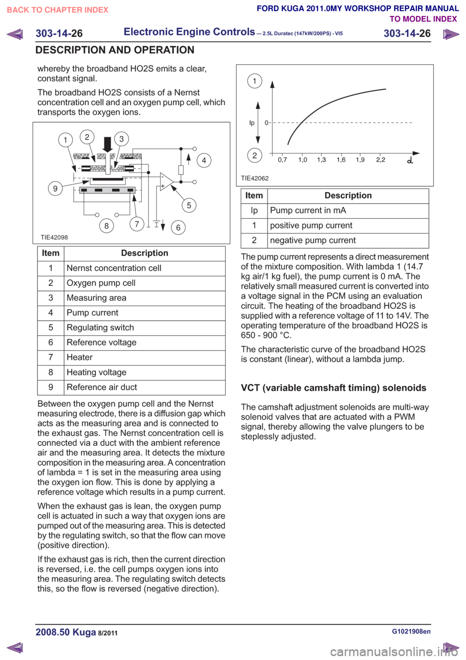
whereby the broadband HO2S emits a clear,
constant signal.
The broadband HO2S consists of a Nernst
concentration cell and an oxygen pump cell, which
transports the oxygen ions.
TIE42098
5
7
9
12
86
4
3
Description
Item
Nernst concentration cell
1
Oxygen pump cell
2
Measuring area
3
Pump current
4
Regulating switch
5
Reference voltage
6
Heater
7
Heating voltage
8
Reference air duct
9
Between the oxygen pump cell and the Nernst
measuring electrode, there is a diffusion gap which
acts as the measuring area and is connected to
the exhaust gas. The Nernst concentration cell is
connected via a duct with the ambient reference
air and the measuring area. It detects the mixture
composition in the measuring area. A concentration
of lambda = 1 is set in the measuring area using
the oxygen ion flow. This is done by applying a
reference voltage which results in a pump current.
When the exhaust gas is lean, the oxygen pump
cell is actuated in such a way that oxygen ions are
pumped out of the measuring area. This is detected
by the regulating switch, so that the flow can move
(positive direction).
If the exhaust gas is rich, then the current direction
is reversed, i.e. the cell pumps oxygen ions into
the measuring area. The regulating switch detects
this, so the flow is reversed (negative direction).
TIE42062
1
2
Description
Item
Pump current in mA
Ip
positive pump current
1
negative pump current
2
The pump current represents a direct measurement
of the mixture composition. With lambda 1 (14.7
kg air/1 kg fuel), the pump current is 0 mA. The
relatively small measured current is converted into
a voltage signal in the PCM using an evaluation
circuit. The heating of the broadband HO2S is
supplied with a reference voltage of 11 to 14V. The
operating temperature of the broadband HO2S is
650 - 900 °C.
The characteristic curve of the broadband HO2S
is constant (linear), without a lambda jump.
VCT (variable camshaft timing) solenoids
The camshaft adjustment solenoids are multi-way
solenoid valves that are actuated with a PWM
signal, thereby allowing the valve plungers to be
steplessly adjusted.
G1021908en2008.50 Kuga8/2011
303-14- 26
Electronic Engine Controls— 2.5L Duratec (147kW/200PS) - VI5303-14-
26
DESCRIPTION AND OPERATION
TO MODEL INDEX
BACK TO CHAPTER INDEX
FORD KUGA 2011.0MY WORKSHOP REPAIR MANUAL
Page 1831 of 2057
E112323
1
2
7
6
4
5
3
10
9
11
12
Description
Item
The TSS sensor
1
The OSS sensor
2
PWM (pulse width modulation)- solenoid
valve – TCC (torque converter clutch)
(SLU)
3
PWM solenoid valve – shift pressure (SLS)
4
Shift solenoid S1
5
Shift solenoid S4
6Description
Item
Shift solenoid S3
7
Shift solenoid S5
8
Shift solenoid S2
9
The TFT (transmission fluid temperature)
sensor
10
PWM solenoid valve for main line pressure
(SLT)
11
TCM with integrated TR sensor
12
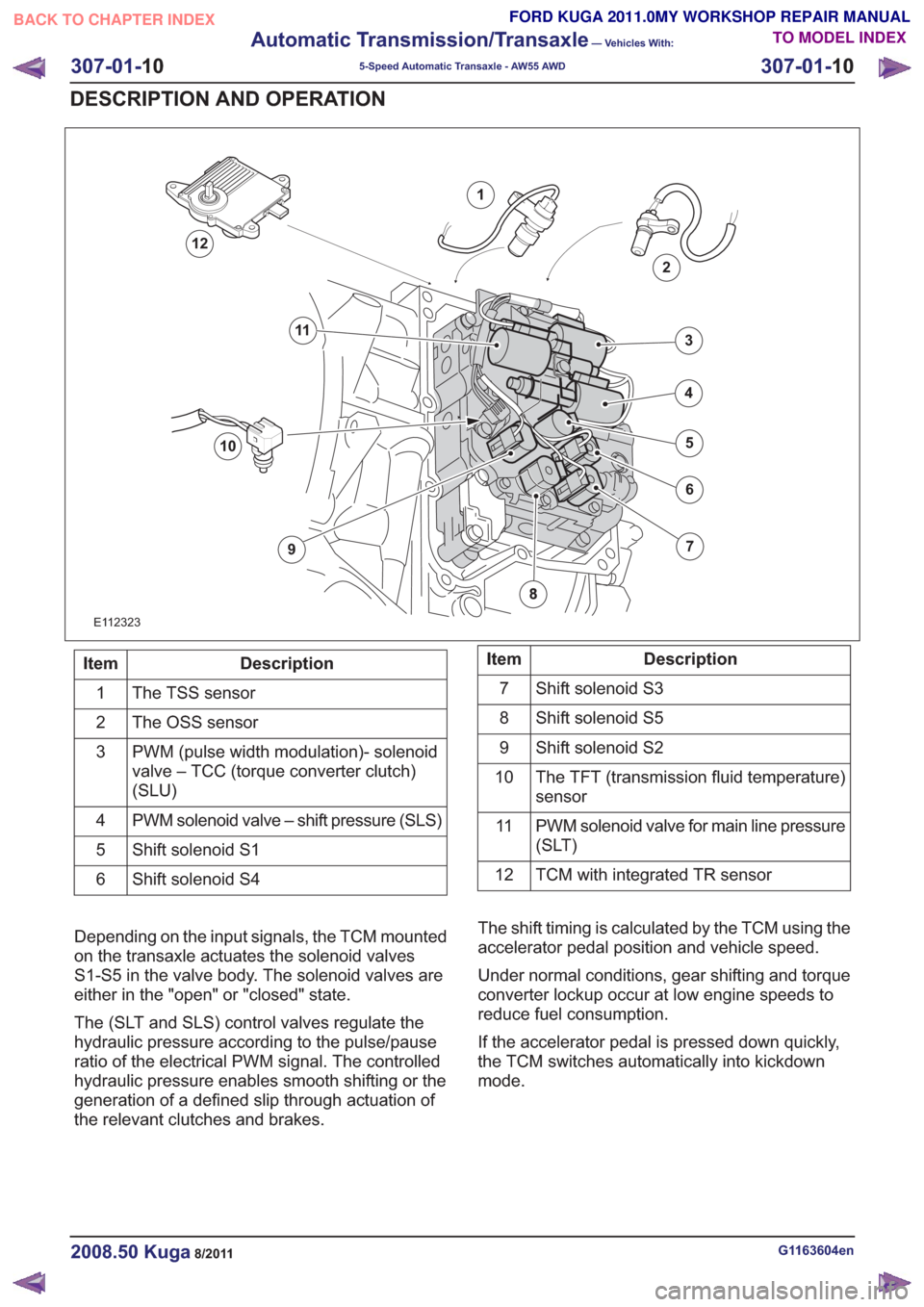
Depending on the input signals, the TCM mounted
on the transaxle actuates the solenoid valves
S1-S5 in the valve body. The solenoid valves are
either in the "open" or "closed" state.
The (SLT and SLS) control valves regulate the
hydraulic pressure according to the pulse/pause
ratio of the electrical PWM signal. The controlled
hydraulic pressure enables smooth shifting or the
generation of a defined slip through actuation of
the relevant clutches and brakes. The shift timing is calculated by the TCM using the
accelerator pedal position and vehicle speed.
Under normal conditions, gear shifting and torque
converter lockup occur at low engine speeds to
reduce fuel consumption.
If the accelerator pedal is pressed down quickly,
the TCM switches automatically into kickdown
mode.
G1163604en2008.50 Kuga8/2011
307-01-
10
Automatic Transmission/Transaxle
— Vehicles With:
5-Speed Automatic Transaxle - AW55 AWD
307-01- 10
DESCRIPTION AND OPERATION
TO MODEL INDEX
BACK TO CHAPTER INDEX
FORD KUGA 2011.0MY WORKSHOP REPAIR MANUAL
Page 1849 of 2057
21
22 20 19
15 14 13
161718 12
876
9
10
11 5
3
42121
22 20 19
15 14 13
161718 12
876
9
10
11 5
3
421
E125671
Description
Item
Shift solenoid valve S1 (+)
1
Shift solenoid valve (S2) (+)
2
PWM solenoid valve – main line pressure
(SLT) (+)
3
not assigned
4
not assigned
5
PWM solenoid valve – main pressure line
(SLT) (–)
6
PWM solendoid valve – TCC (SLU) (–)
7
not assigned
8
PWM solenoid valve – TCC (SLU) (+)
9
PWM solenoid valve – shift pressure (SLS)
(–)
10Description
Item
not assigned
11
not assigned
12
TFT sensor (–)
13
TFT sensor (+)
14
not assigned
15
PWM solenoid valve – shift pressure (SLS)
(+)
16
Shift solenoid valve (S3) (+)
17
not assigned
18
not assigned
19
not assigned
20
Shift solenoid valve (S5) (+)
21
Shift solenoid valve (S4) (+)
22
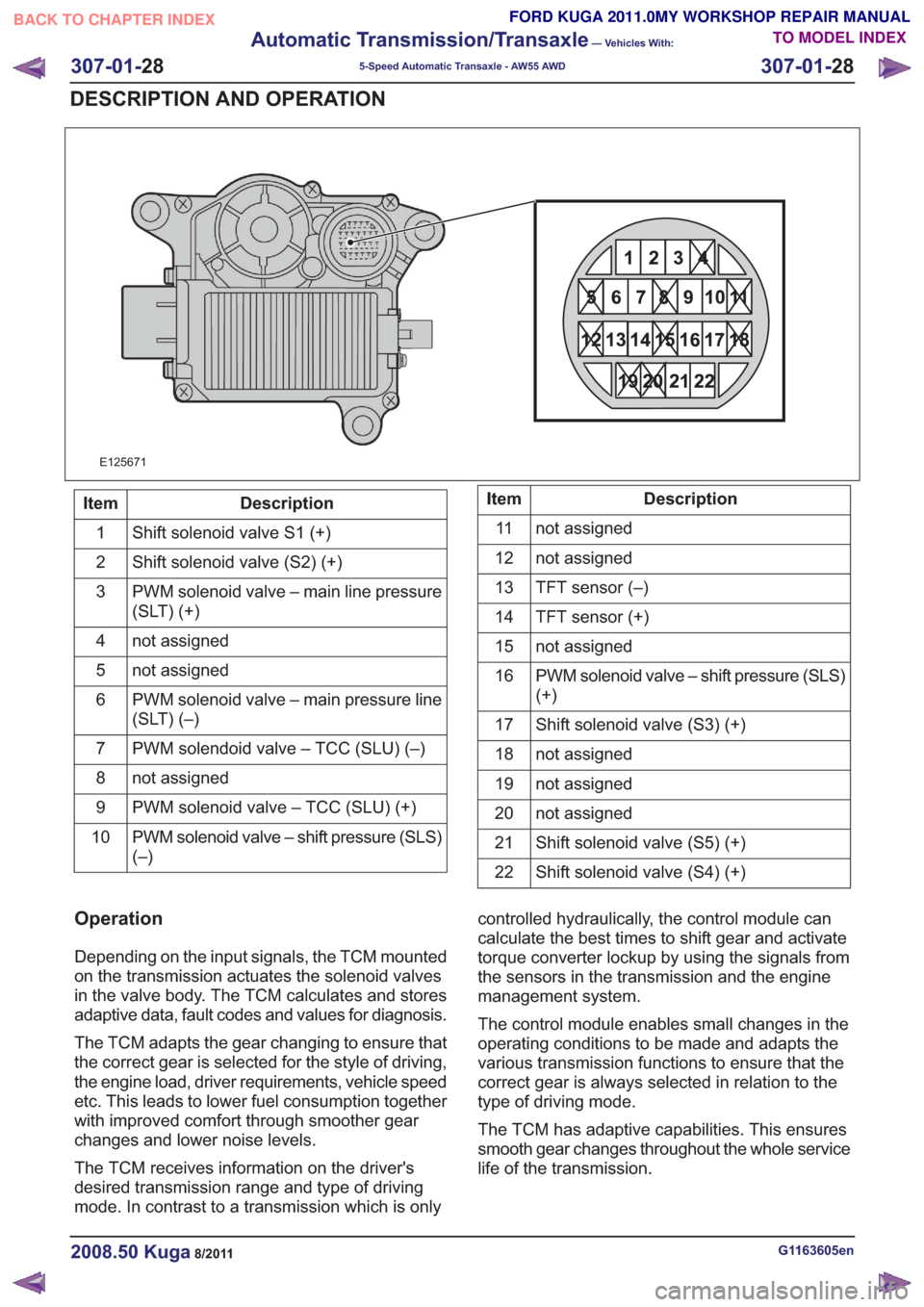
Operation
Depending on the input signals, the TCM mounted
on the transmission actuates the solenoid valves
in the valve body. The TCM calculates and stores
adaptive data, fault codes and values for diagnosis.
The TCM adapts the gear changing to ensure that
the correct gear is selected for the style of driving,
the engine load, driver requirements, vehicle speed
etc. This leads to lower fuel consumption together
with improved comfort through smoother gear
changes and lower noise levels.
The TCM receives information on the driver's
desired transmission range and type of driving
mode. In contrast to a transmission which is only controlled hydraulically, the control module can
calculate the best times to shift gear and activate
torque converter lockup by using the signals from
the sensors in the transmission and the engine
management system.
The control module enables small changes in the
operating conditions to be made and adapts the
various transmission functions to ensure that the
correct gear is always selected in relation to the
type of driving mode.
The TCM has adaptive capabilities. This ensures
smooth gear changes throughout the whole service
life of the transmission.
G1163605en2008.50 Kuga8/2011
307-01-
28
Automatic Transmission/Transaxle
— Vehicles With:
5-Speed Automatic Transaxle - AW55 AWD
307-01- 28
DESCRIPTION AND OPERATION
TO MODEL INDEX
BACK TO CHAPTER INDEX
FORD KUGA 2011.0MY WORKSHOP REPAIR MANUAL
Page 1867 of 2057
E125595
2
3
4
5678
1
Description
Item
PWM solenoid valve for main line pressure
(SLT)
1
PWM- solenoid valve – TCC (SLU)
2
PWM solenoid valve – shift pressure (SLS)
3
Shift solenoid S4
4Description
Item
Shift solenoid S3
5
Shift solenoid S1
6
Shift solenoid S5
7
Shift solenoid S2
8
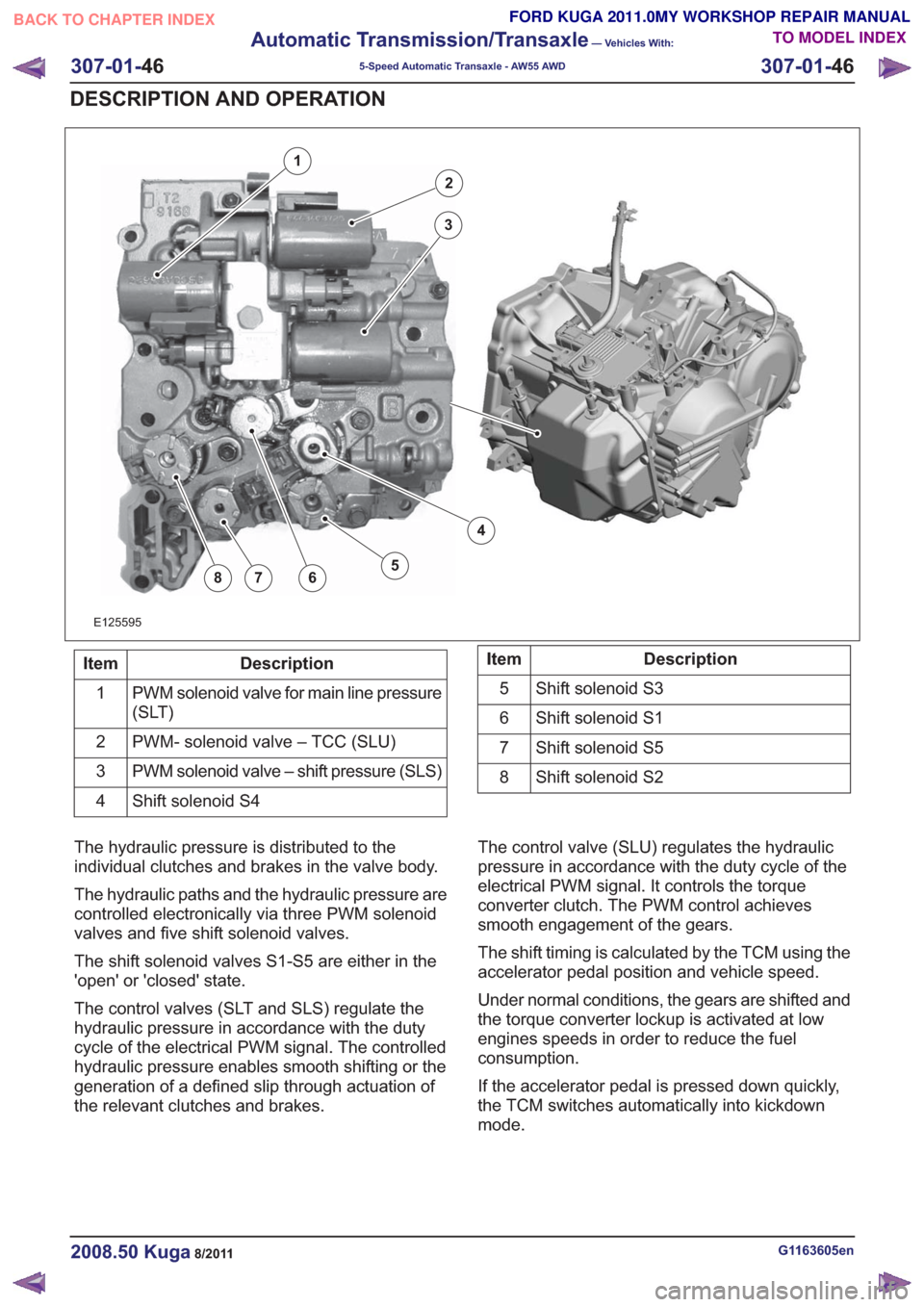
The hydraulic pressure is distributed to the
individual clutches and brakes in the valve body.
The hydraulic paths and the hydraulic pressure are
controlled electronically via three PWM solenoid
valves and five shift solenoid valves.
The shift solenoid valves S1-S5 are either in the
'open' or 'closed' state.
The control valves (SLT and SLS) regulate the
hydraulic pressure in accordance with the duty
cycle of the electrical PWM signal. The controlled
hydraulic pressure enables smooth shifting or the
generation of a defined slip through actuation of
the relevant clutches and brakes. The control valve (SLU) regulates the hydraulic
pressure in accordance with the duty cycle of the
electrical PWM signal. It controls the torque
converter clutch. The PWM control achieves
smooth engagement of the gears.
The shift timing is calculated by the TCM using the
accelerator pedal position and vehicle speed.
Under normal conditions, the gears are shifted and
the torque converter lockup is activated at low
engines speeds in order to reduce the fuel
consumption.
If the accelerator pedal is pressed down quickly,
the TCM switches automatically into kickdown
mode.
G1163605en2008.50 Kuga8/2011
307-01-
46
Automatic Transmission/Transaxle
— Vehicles With:
5-Speed Automatic Transaxle - AW55 AWD
307-01- 46
DESCRIPTION AND OPERATION
TO MODEL INDEX
BACK TO CHAPTER INDEX
FORD KUGA 2011.0MY WORKSHOP REPAIR MANUAL