2011 FORD KUGA coolant
[x] Cancel search: coolantPage 1676 of 2057
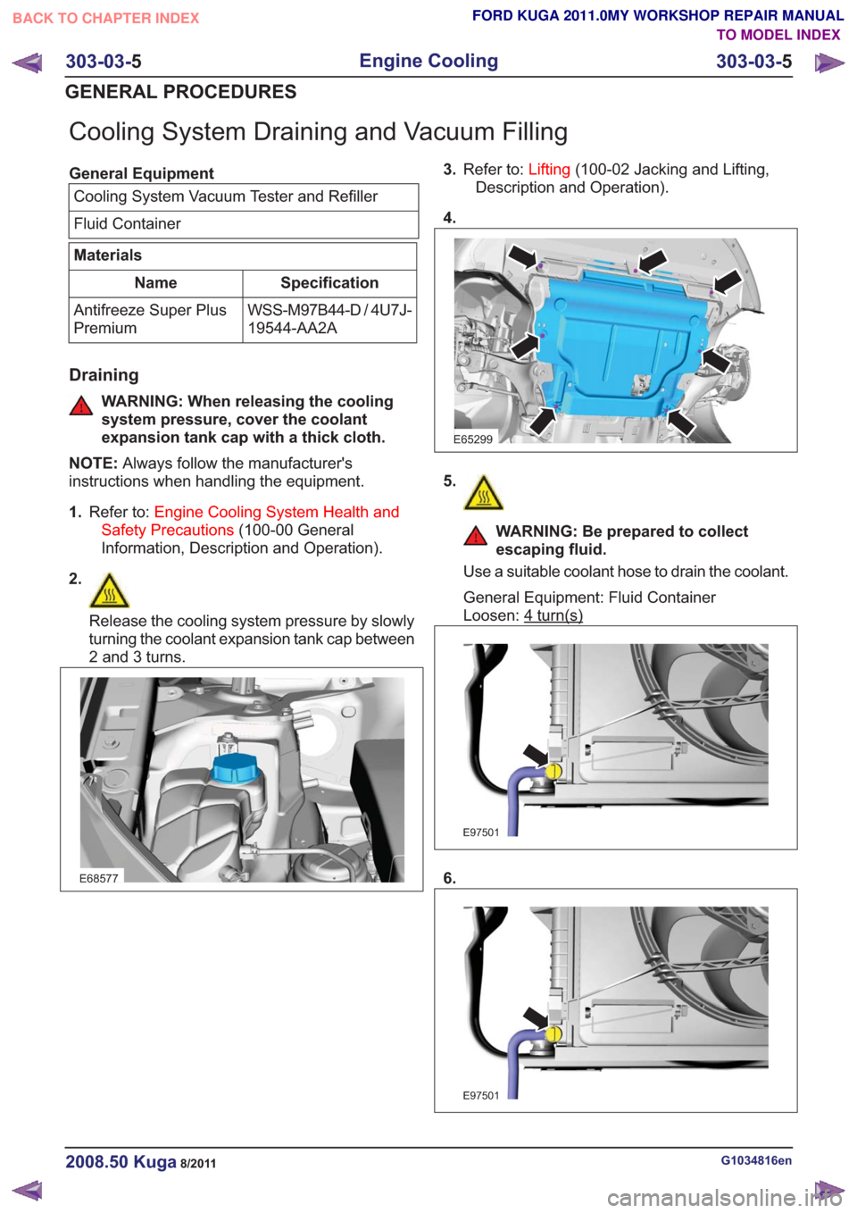
Cooling System Draining and Vacuum Filling
General EquipmentCooling System Vacuum Tester and Refiller
Fluid Container
Materials
Specification
Name
WSS-M97B44-D / 4U7J-
19544-AA2A
Antifreeze Super Plus
Premium
Draining
WARNING: When releasing the cooling
system pressure, cover the coolant
expansion tank cap with a thick cloth.
NOTE: Always follow the manufacturer's
instructions when handling the equipment.
1. Refer to: Engine Cooling System Health and
Safety Precautions (100-00 General
Information, Description and Operation).
2.
Release the cooling system pressure by slowly
turning the coolant expansion tank cap between
2 and 3 turns.
E68577
3. Refer to: Lifting(100-02 Jacking and Lifting,
Description and Operation).
4.
E65299
5.
WARNING: Be prepared to collect
escaping fluid.
Use a suitable coolant hose to drain the coolant.
General Equipment: Fluid Container
Loosen: 4
turn(s)
E97501
6.
E97501
G1034816en2008.50 Kuga8/2011
303-03- 5
Engine Cooling
303-03- 5
GENERAL PROCEDURES
TO MODEL INDEX
BACK TO CHAPTER INDEX
FORD KUGA 2011.0MY WORKSHOP REPAIR MANUAL
Page 1677 of 2057
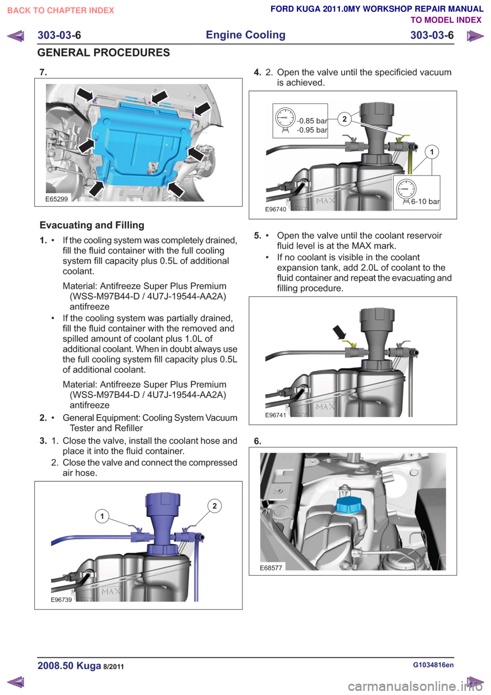
7.
E65299
Evacuating and Filling
1.If the cooling system was completely drained,
fill the fluid container with the full cooling
•
system fill capacity plus 0.5L of additional
coolant.
Material: Antifreeze Super Plus Premium(WSS-M97B44-D / 4U7J-19544-AA2A)
antifreeze
• If the cooling system was partially drained, fill the fluid container with the removed and
spilled amount of coolant plus 1.0L of
additional coolant. When in doubt always use
the full cooling system fill capacity plus 0.5L
of additional coolant.
Material: Antifreeze Super Plus Premium(WSS-M97B44-D / 4U7J-19544-AA2A)
antifreeze
2. General Equipment: Cooling System Vacuum
Tester and Refiller
•
3. Close the valve, install the coolant hose and
place it into the fluid container.
1.
2. Close the valve and connect the compressed
air hose.
E96739
1
2
4. Open the valve until the specificied vacuum
is achieved.
2.
E967406-10 bar
1
-0.85 bar
-0.95 bar2
5.
Open the valve until the coolant reservoir
fluid level is at the MAX mark.
•
• If no coolant is visible in the coolant
expansion tank, add 2.0L of coolant to the
fluid container and repeat the evacuating and
filling procedure.
E96741
6.
E68577
G1034816en2008.50 Kuga8/2011
303-03- 6
Engine Cooling
303-03- 6
GENERAL PROCEDURES
TO MODEL INDEX
BACK TO CHAPTER INDEX
FORD KUGA 2011.0MY WORKSHOP REPAIR MANUAL
Page 1681 of 2057
Coolant Pump — 2.5L Duratec (147kW/200PS) - VI5(24 404 0)
General EquipmentTrolley Jack
Removal
NOTE: Removal steps in this procedure may
contain installation details.
1. Drain the cooling system.
Refer to: Cooling System Draining and Vacuum
Filling (303-03 Engine Cooling, General
Procedures).
2. Remove the timing belt.
Refer to: Timing Belt (303-01 Engine - 2.5L
Duratec (147kW/200PS) - VI5, Removal and
Installation).
3. CAUTION: Use a wooden block to protect the oil pan when supporting the
engine.
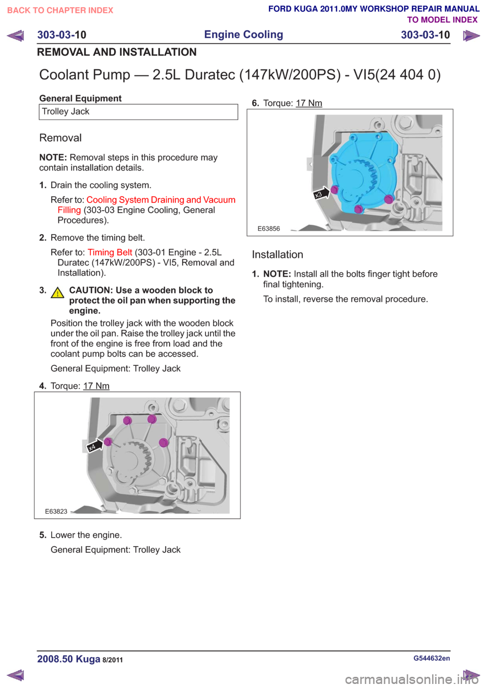
Position the trolley jack with the wooden block
under the oil pan. Raise the trolley jack until the
front of the engine is free from load and the
coolant pump bolts can be accessed.
General Equipment: Trolley Jack
4. Torque: 17
Nm
E63823
x4
5.Lower the engine.
General Equipment: Trolley Jack 6.
Torque: 17
Nm
x3
E63856
Installation
1. NOTE: Install all the bolts finger tight before
final tightening.
To install, reverse the removal procedure.
G544632en2008.50 Kuga8/2011
303-03- 10
Engine Cooling
303-03- 10
REMOVAL AND INSTALLATION
TO MODEL INDEX
BACK TO CHAPTER INDEX
FORD KUGA 2011.0MY WORKSHOP REPAIR MANUAL
Page 1697 of 2057
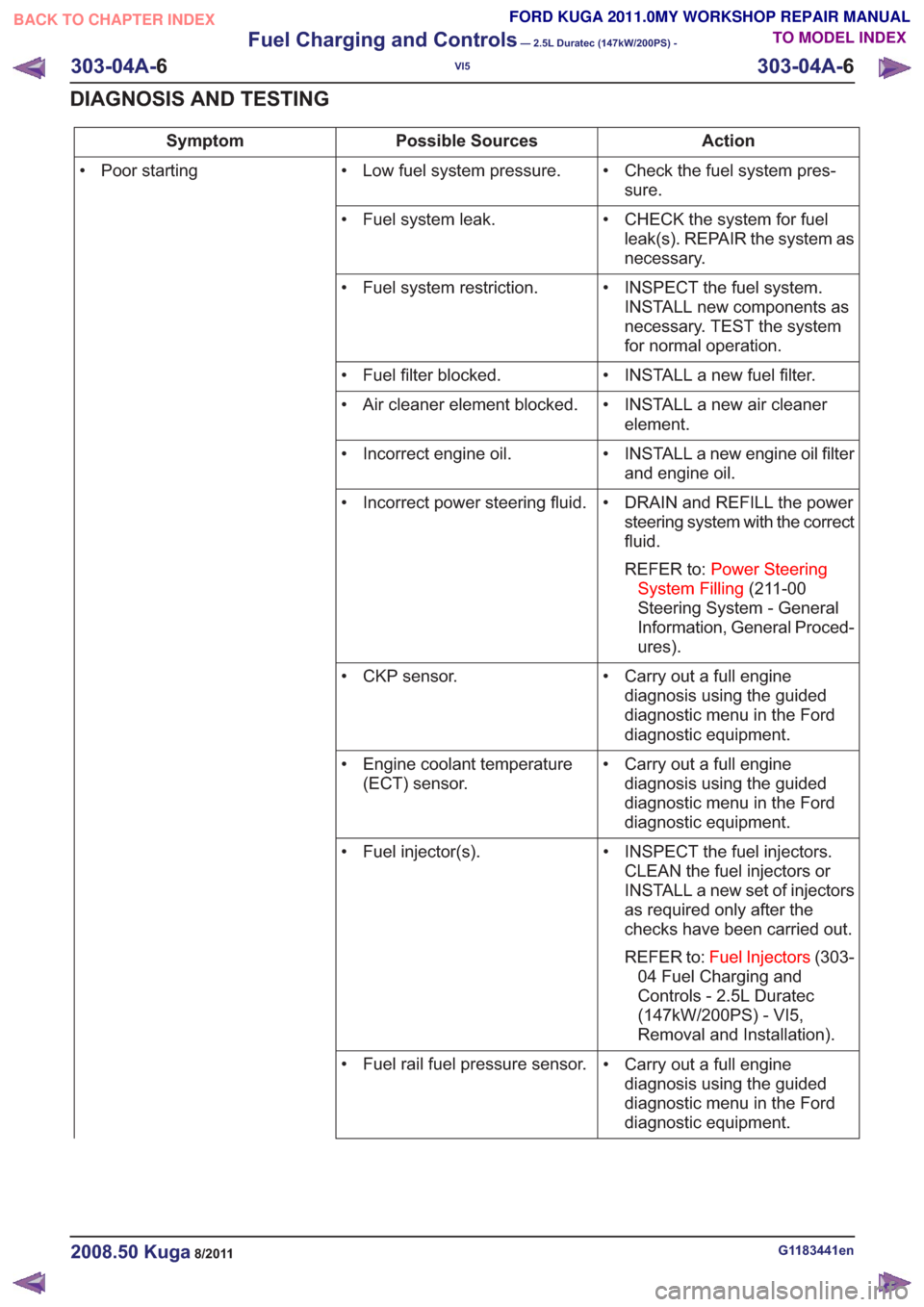
Action
Possible Sources
Symptom
• Check the fuel system pres-sure.
• Low fuel system pressure.
• Poor starting
• CHECK the system for fuelleak(s). REPAIR the system as
necessary.
• Fuel system leak.
• INSPECT the fuel system.INSTALL new components as
necessary. TEST the system
for normal operation.
• Fuel system restriction.
• INSTALL a new fuel filter.
• Fuel filter blocked.
• INSTALL a new air cleanerelement.
• Air cleaner element blocked.
• INSTALL a new engine oil filterand engine oil.
• Incorrect engine oil.
• DRAIN and REFILL the powersteering system with the correct
fluid.
REFER to: Power Steering
System Filling (211-00
Steering System - General
Information, General Proced-
ures).
• Incorrect power steering fluid.
• Carry out a full enginediagnosis using the guided
diagnostic menu in the Ford
diagnostic equipment.
• CKP sensor.
• Carry out a full enginediagnosis using the guided
diagnostic menu in the Ford
diagnostic equipment.
• Engine coolant temperature
(ECT) sensor.
• INSPECT the fuel injectors.CLEAN the fuel injectors or
INSTALL a new set of injectors
as required only after the
checks have been carried out.
REFER to: Fuel Injectors (303-
04 Fuel Charging and
Controls - 2.5L Duratec
(147kW/200PS) - VI5,
Removal and Installation).
• Fuel injector(s).
• Carry out a full enginediagnosis using the guided
diagnostic menu in the Ford
diagnostic equipment.
• Fuel rail fuel pressure sensor.
G1183441en2008.50 Kuga8/2011
303-04A-
6
Fuel Charging and Controls
— 2.5L Duratec (147kW/200PS) -
VI5
303-04A- 6
DIAGNOSIS AND TESTING
TO MODEL INDEX
BACK TO CHAPTER INDEX
FORD KUGA 2011.0MY WORKSHOP REPAIR MANUAL
Page 1706 of 2057
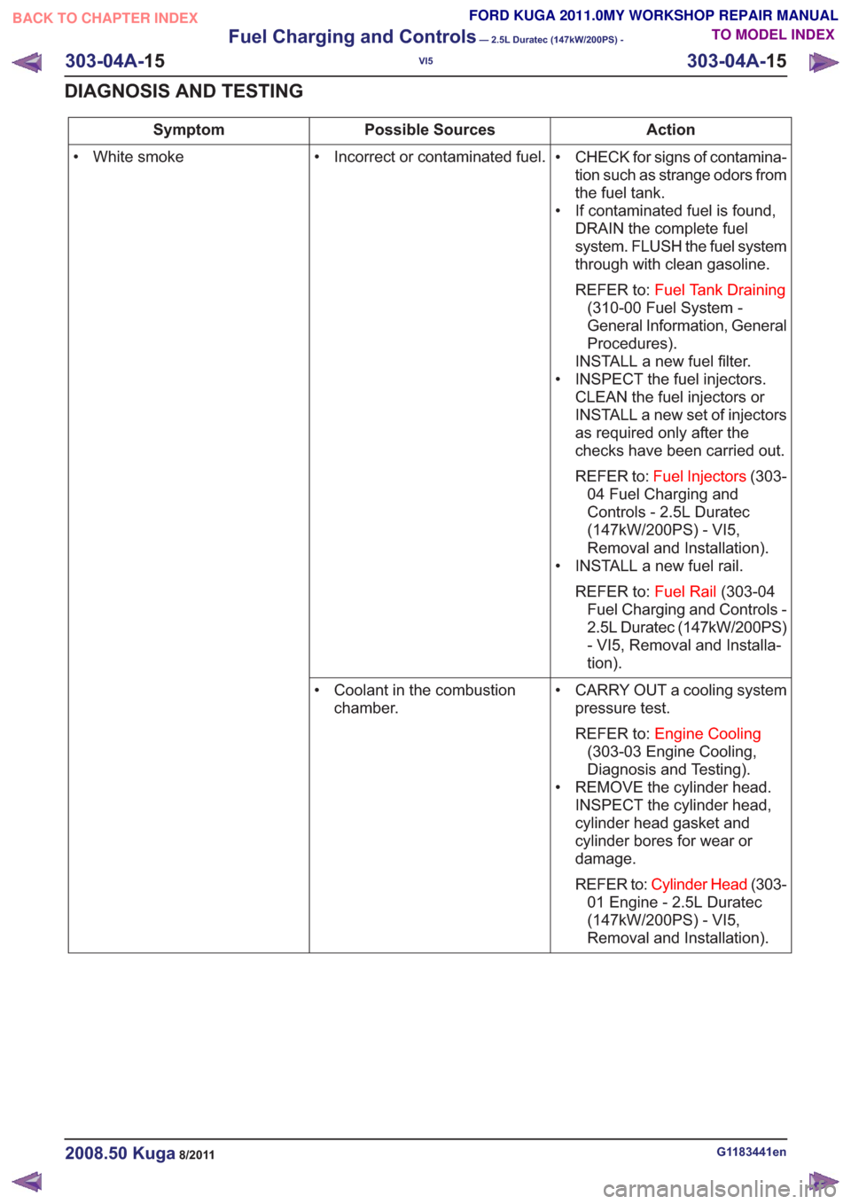
Action
Possible Sources
Symptom
• CHECK for signs of contamina-tion such as strange odors from
the fuel tank.
• If contaminated fuel is found, DRAIN the complete fuel
system. FLUSH the fuel system
through with clean gasoline.
REFER to: Fuel Tank Draining
(310-00 Fuel System -
General Information, General
Procedures).
INSTALL a new fuel filter.
• INSPECT the fuel injectors. CLEAN the fuel injectors or
INSTALL a new set of injectors
as required only after the
checks have been carried out.
REFER to: Fuel Injectors (303-
04 Fuel Charging and
Controls - 2.5L Duratec
(147kW/200PS) - VI5,
Removal and Installation).
• INSTALL a new fuel rail.
REFER to: Fuel Rail(303-04
Fuel Charging and Controls -
2.5L Duratec (147kW/200PS)
- VI5, Removal and Installa-
tion).
• Incorrect or contaminated fuel.
• White smoke
• CARRY OUT a cooling systempressure test.
REFER to: Engine Cooling
(303-03 Engine Cooling,
Diagnosis and Testing).
• REMOVE the cylinder head. INSPECT the cylinder head,
cylinder head gasket and
cylinder bores for wear or
damage.
REFER to: Cylinder Head (303-
01 Engine - 2.5L Duratec
(147kW/200PS) - VI5,
Removal and Installation).
• Coolant in the combustion
chamber.
G1183441en2008.50 Kuga8/2011
303-04A- 15
Fuel Charging and Controls
— 2.5L Duratec (147kW/200PS) -
VI5
303-04A- 15
DIAGNOSIS AND TESTING
TO MODEL INDEX
BACK TO CHAPTER INDEX
FORD KUGA 2011.0MY WORKSHOP REPAIR MANUAL
Page 1719 of 2057
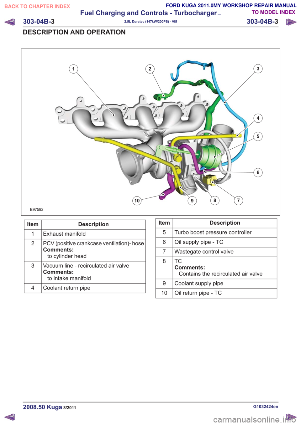
6
79108
123
4
5
6
79108
E97592
Description
Item
Exhaust manifold
1
PCV (positive crankcase ventilation)- hose
Comments:to cylinder head
2
Vacuum line - recirculated air valve
Comments:to intake manifold
3
Coolant return pipe
4Description
Item
Turbo boost pressure controller
5
Oil supply pipe - TC
6
Wastegate control valve
7
TC
Comments:Contains the recirculated air valve
8
Coolant supply pipe
9
Oil return pipe - TC
10
G1032424en2008.50 Kuga8/2011
303-04B- 3
Fuel Charging and Controls - Turbocharger
—
2.5L Duratec (147kW/200PS) - VI5
303-04B- 3
DESCRIPTION AND OPERATION
TO MODEL INDEX
BACK TO CHAPTER INDEX
FORD KUGA 2011.0MY WORKSHOP REPAIR MANUAL
Page 1720 of 2057
Turbocharger – Overview
Turbocharger(s)
CAUTION: Do not switch off the engine
while it is running at high speed. If the
engine is switched off while it is running
at high speed, the turbocharger will
continue to run after the engine oil
pressure has already dropped to zero. This
will cause premature wear in the
turbocharger bearings.
A TC consists of an exhaust turbine located in the
exhaust gas flow, this turbine is connected to a
compressor by a shaft. The turbine is made to
rotate by the exhaust gas flow from the engine and
thus drives the compressor. The compressor
increases the pressure in the engine intake tract
so that a greater mass of air enters the cylinder
during the intake stroke.
The turbine housing of the TC is integrated into the
exhaust manifold. This construction offers
thermodynamic advantages compared with the
usual construction, the maximum exhaust
temperature is up to 1050°C.
The maximum boost pressure is 0.65 bar.
The exhaust manifold is secured to the exhaust
side of the cylinder head with 12 self-locking nuts.
The exhaust manifold gasket is a multi-layer steel
gasket and cannot be reused. In order to
compensate for the thermal expansion of the
exhaust manifold, the flange of the TC is provided
with two grooves.
The TC and the exhaust manifold are joined by a
hose clip. The hose clip must not be loosened or
removed. The TC and the exhaust manifold are
not available as separate replacement parts,
exchange is only possible as a complete unit.
The turbocharger heat shield is secured to the
exhaust manifold by four bolts. Two of the bolts
have spring washers underneath their heads.
During removal, make a note of the installation
location of the spring washers to refer to during
installation.
The recirculated air valve is built into the TC
housing and cannot be changed.
The Ford diagnostic unit can test the operation of
the wastegate control valve using actuator
diagnosis.
The boost pressure regulator is set in the factory.
Adjustments to the boost pressure regulator must never be attempted. A red colored seal is applied
to the adjustment nut of the operating rod, in order
to monitor the factory setting of the boost pressure.
The bearings of the TC are lubricated with engine
oil. The engine oil passes from the cylinder block
through the oil supply pipe to the TC. The oil is
returned to the oil pan through the oil return pipe,
The TC is cooled by the engine coolant circuit.
When installing hoses and lines, make certain that
their ends are free of oil residues and dirt.
G1032425en2008.50 Kuga8/2011
303-04B-
4
Fuel Charging and Controls - Turbocharger
—
2.5L Duratec (147kW/200PS) - VI5
303-04B- 4
DESCRIPTION AND OPERATION
TO MODEL INDEX
BACK TO CHAPTER INDEX
FORD KUGA 2011.0MY WORKSHOP REPAIR MANUAL
Page 1775 of 2057
SECTION 303-14 Electronic Engine Controls— 2.5L Duratec
(147kW/200PS) - VI5
VEHICLE APPLICATION: 2008.50 Kuga
PA G E
CONTENTS
DESCRIPTION AND OPERATION
303-14-3
Electronic Engine Controls (Component Location) .............................................................
303-14-7
Electronic Engine Controls (Overview) ........................................................................\
.......
303-14-7
General overview ........................................................................\
........................................
303-14-8
Powertrain Control Module (PCM) ........................................................................\
..............
303-14-8
Knock Sensor ........................................................................\
.............................................
303-14-8
Camshaft Position (CMP) Sensor ........................................................................\
...............
303-14-9
Crankshaft Position (CKP) sensor ........................................................................\
..............
303-14-9
Camshaft adjuster solenoid valve........................................................................\
...............
303-14-9
Manifold absolute pressure and temperature sensor .........................................................
303-14-9
Accelerator pedal position (APP) sensor ........................................................................\
....
303-14-10
Throttle control unit ........................................................................\
.....................................
303-14-10
Engine Coolant Temperature (ECT) sensor.......................................................................
303-14-10
Ignition coil-on-plug ........................................................................\
....................................
303-14-12
Electronic Engine Controls (System Operation and Component Description) ...................
303-14-12
System Diagram ........................................................................\
.........................................
303-14-16
System Operation ........................................................................\
.......................................
303-14-18
Speed and TDC recording ........................................................................\
......................
303-14-19
Calculation of the ignition angle ........................................................................\
..............
303-14-20
Engine fueling ........................................................................\
.........................................
303-14-22
Engine speed control ........................................................................\
..............................
303-14-22
Oil monitoring ........................................................................\
..........................................
303-14-23
Calculation of valve timing adjustment angle..................................................................
303-14-23
Boost pressure control ........................................................................\
............................
303-14-24
Starting process ........................................................................\
......................................
303-14-24
Alternator control (Smart Charge) ........................................................................\
...........
303-14-24
Component Description ........................................................................\
..............................
303-14-24
CKP sensor ........................................................................\
.............................................
303-14-25
Broadband HO2S ........................................................................\
...................................
303-14-26
VCT (variable camshaft timing) solenoids ......................................................................
303-14-27
MAF sensor ........................................................................\
.............................................
303-14-28
APP sensor ........................................................................\
.............................................
303-14-29
CPP sensor ........................................................................\
.............................................
303-14-29
BPP switches ........................................................................\
..........................................
303-14-30
Air conditioning (A/C) pressure sensor ........................................................................\
...
303-14-30
Throttle
control unit ........................................................................\
.................................
303-14-31
ECT sensor ........................................................................\
.............................................
303-14-31
Cooling fan module ........................................................................\
.................................
303-14-32
injectors........................................................................\
...................................................
303-14-32
Ignition coil-on-plug ........................................................................\
.................................
303-14-33
Fuel pressure/fuel temperature sensor ........................................................................\
...
303-14-33
Wastegate control valve ........................................................................\
..........................
303-14-34
Engine oil level, temperature and quality sensor ............................................................
303-14-1
Electronic Engine Controls— 2.5L Duratec (147kW/200PS) - VI5303-14-
1
.
TO MODEL INDEX
BACK TO CHAPTER INDEX
PAGE 1 OF 2
FORD KUGA 2011.0MY WORKSHOP REPAIR MANUAL