2011 FORD KUGA Anti Lock Brake System
[x] Cancel search: Anti Lock Brake SystemPage 1426 of 2057
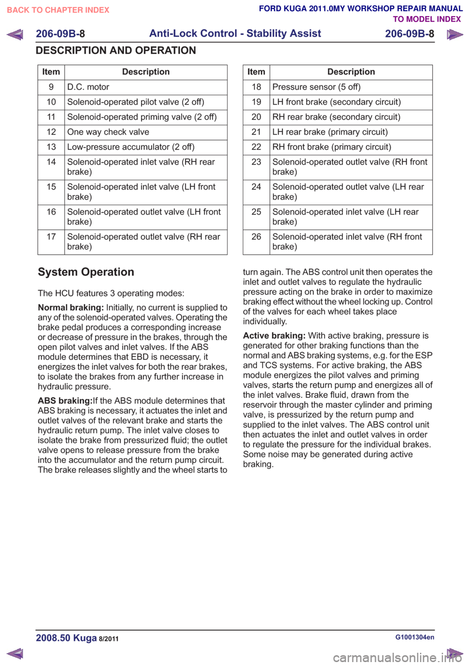
Description
Item
D.C. motor
9
Solenoid-operated pilot valve (2 off)
10
Solenoid-operated priming valve (2 off)
11
One way check valve
12
Low-pressure accumulator (2 off)
13
Solenoid-operated inlet valve (RH rear
brake)
14
Solenoid-operated inlet valve (LH front
brake)
15
Solenoid-operated outlet valve (LH front
brake)
16
Solenoid-operated outlet valve (RH rear
brake)
17Description
Item
Pressure sensor (5 off)
18
LH front brake (secondary circuit)
19
RH rear brake (secondary circuit)
20
LH rear brake (primary circuit)
21
RH front brake (primary circuit)
22
Solenoid-operated outlet valve (RH front
brake)
23
Solenoid-operated outlet valve (LH rear
brake)
24
Solenoid-operated inlet valve (LH rear
brake)
25
Solenoid-operated inlet valve (RH front
brake)
26
System Operation
The HCU features 3 operating modes:
Normal braking:
Initially, no current is supplied to
any of the solenoid-operated valves. Operating the
brake pedal produces a corresponding increase
or decrease of pressure in the brakes, through the
open pilot valves and inlet valves. If the ABS
module determines that EBD is necessary, it
energizes the inlet valves for both the rear brakes,
to isolate the brakes from any further increase in
hydraulic pressure.
ABS braking: If the ABS module determines that
ABS braking is necessary, it actuates the inlet and
outlet valves of the relevant brake and starts the
hydraulic return pump. The inlet valve closes to
isolate the brake from pressurized fluid; the outlet
valve opens to release pressure from the brake
into the accumulator and the return pump circuit.
The brake releases slightly and the wheel starts to turn again. The ABS control unit then operates the
inlet and outlet valves to regulate the hydraulic
pressure acting on the brake in order to maximize
braking effect without the wheel locking up. Control
of the valves for each wheel takes place
individually.
Active braking:
With active braking, pressure is
generated for other braking functions than the
normal and ABS braking systems, e.g. for the ESP
and TCS systems. For active braking, the ABS
module energizes the pilot valves and priming
valves, starts the return pump and energizes all of
the inlet valves. Brake fluid, drawn from the
reservoir through the master cylinder and priming
valve, is pressurized by the return pump and
supplied to the inlet valves. The ABS control unit
then actuates the inlet and outlet valves in order
to regulate the pressure for the individual brakes.
Some noise may be generated during active
braking.
G1001304en2008.50 Kuga8/2011
206-09B- 8
Anti-Lock Control - Stability Assist
206-09B- 8
DESCRIPTION AND OPERATION
TO MODEL INDEX
BACK TO CHAPTER INDEX
FORD KUGA 2011.0MY WORKSHOP REPAIR MANUAL
Page 1428 of 2057
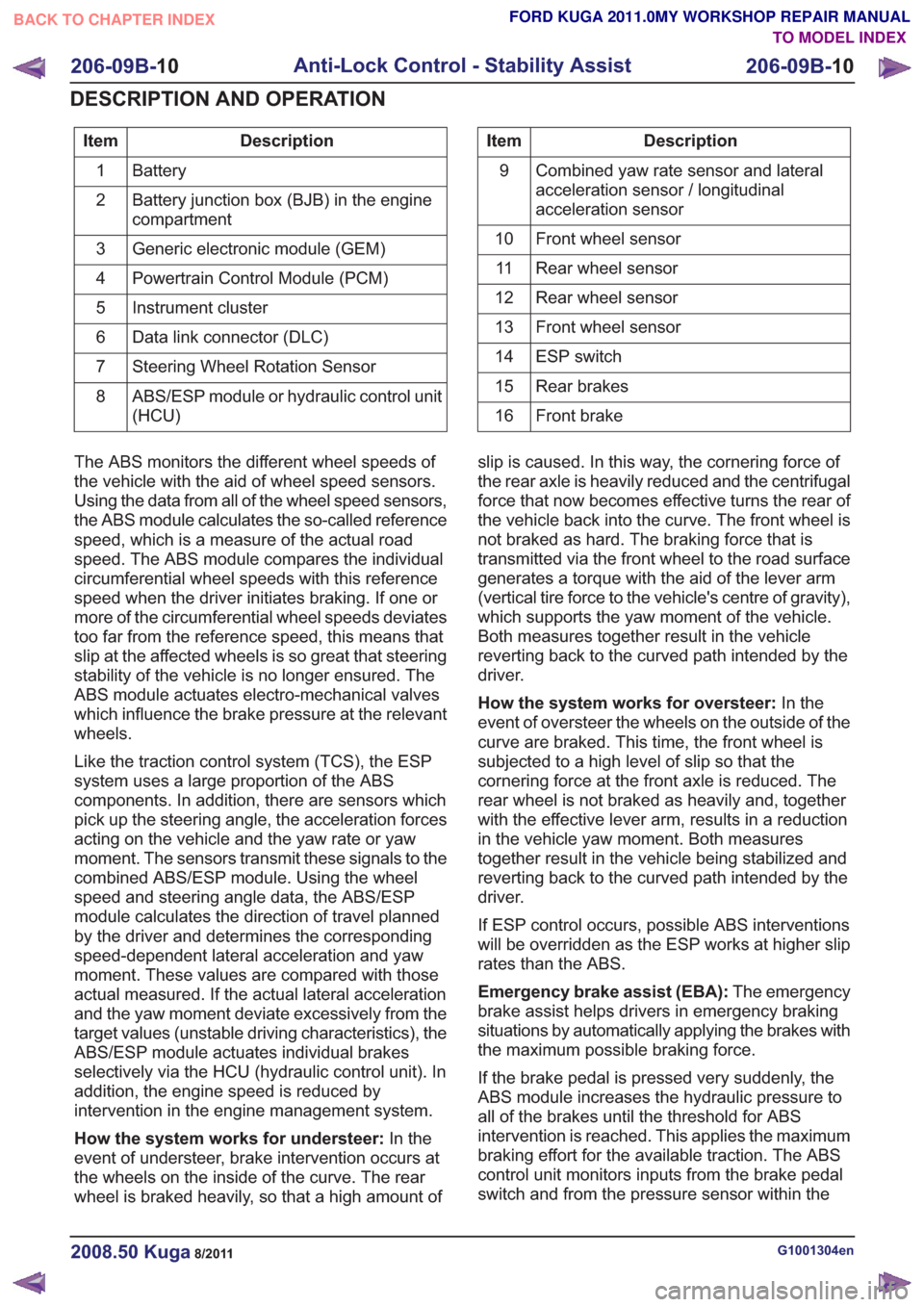
Description
Item
Battery
1
Battery junction box (BJB) in the engine
compartment
2
Generic electronic module (GEM)
3
Powertrain Control Module (PCM)
4
Instrument cluster
5
Data link connector (DLC)
6
Steering Wheel Rotation Sensor
7
ABS/ESP module or hydraulic control unit
(HCU)
8Description
Item
Combined yaw rate sensor and lateral
acceleration sensor / longitudinal
acceleration sensor
9
Front wheel sensor
10
Rear wheel sensor
11
Rear wheel sensor
12
Front wheel sensor
13
ESP switch
14
Rear brakes
15
Front brake
16
The ABS monitors the different wheel speeds of
the vehicle with the aid of wheel speed sensors.
Using the data from all of the wheel speed sensors,
the ABS module calculates the so-called reference
speed, which is a measure of the actual road
speed. The ABS module compares the individual
circumferential wheel speeds with this reference
speed when the driver initiates braking. If one or
more of the circumferential wheel speeds deviates
too far from the reference speed, this means that
slip at the affected wheels is so great that steering
stability of the vehicle is no longer ensured. The
ABS module actuates electro-mechanical valves
which influence the brake pressure at the relevant
wheels.
Like the traction control system (TCS), the ESP
system uses a large proportion of the ABS
components. In addition, there are sensors which
pick up the steering angle, the acceleration forces
acting on the vehicle and the yaw rate or yaw
moment. The sensors transmit these signals to the
combined ABS/ESP module. Using the wheel
speed and steering angle data, the ABS/ESP
module calculates the direction of travel planned
by the driver and determines the corresponding
speed-dependent lateral acceleration and yaw
moment. These values are compared with those
actual measured. If the actual lateral acceleration
and the yaw moment deviate excessively from the
target values (unstable driving characteristics), the
ABS/ESP module actuates individual brakes
selectively via the HCU (hydraulic control unit). In
addition, the engine speed is reduced by
intervention in the engine management system.
How the system works for understeer: In the
event of understeer, brake intervention occurs at
the wheels on the inside of the curve. The rear
wheel is braked heavily, so that a high amount of slip is caused. In this way, the cornering force of
the rear axle is heavily reduced and the centrifugal
force that now becomes effective turns the rear of
the vehicle back into the curve. The front wheel is
not braked as hard. The braking force that is
transmitted via the front wheel to the road surface
generates a torque with the aid of the lever arm
(vertical tire force to the vehicle's centre of gravity),
which supports the yaw moment of the vehicle.
Both measures together result in the vehicle
reverting back to the curved path intended by the
driver.
How the system works for oversteer:
In the
event of oversteer the wheels on the outside of the
curve are braked. This time, the front wheel is
subjected to a high level of slip so that the
cornering force at the front axle is reduced. The
rear wheel is not braked as heavily and, together
with the effective lever arm, results in a reduction
in the vehicle yaw moment. Both measures
together result in the vehicle being stabilized and
reverting back to the curved path intended by the
driver.
If ESP control occurs, possible ABS interventions
will be overridden as the ESP works at higher slip
rates than the ABS.
Emergency brake assist (EBA): The emergency
brake assist helps drivers in emergency braking
situations by automatically applying the brakes with
the maximum possible braking force.
If the brake pedal is pressed very suddenly, the
ABS module increases the hydraulic pressure to
all of the brakes until the threshold for ABS
intervention is reached. This applies the maximum
braking effort for the available traction. The ABS
control unit monitors inputs from the brake pedal
switch and from the pressure sensor within the
G1001304en2008.50 Kuga8/2011
206-09B- 10
Anti-Lock Control - Stability Assist
206-09B- 10
DESCRIPTION AND OPERATION
TO MODEL INDEX
BACK TO CHAPTER INDEX
FORD KUGA 2011.0MY WORKSHOP REPAIR MANUAL
Page 1429 of 2057
HCU to check for sudden actuation of the brakes.
With the brake pedal pressed, the ABS module
triggers emergency braking if the rate of increase
of hydraulic pressure exceeds the predetermined
limit.
If the brake pedal is pressed so hard that the ABS
becomes active on the front wheels then the ABS
control unit increases the pressure to the rear
wheel brakes up to the ABS intervention threshold.
EBA operation continues until the driver releases
the brake pedal sufficiently for the hydraulic
pressure in the HCU to drop below a threshold
value stored in the ABS module.
Trailer stability control:If the vehicle is ordered
with a trailer coupling then the Trailer Stability
Control function is integrated in the ESP. The ESP
detects snaking when driving with a trailer and
reduces the speed of the vehicle and trailer through
adapted braking and, if necessary, by also reducing
the engine output until the snaking movement of
the trailer is corrected.
Roll-over protection: The ESP dynamically
determines the tipping tendency of the vehicle and
works in conjunction with the EBA system to
prevent the vehicle from tipping over during
dynamic maneuvers like lane changing or while
negotiating bends.
Emergency brake light: The emergency brake
light automatically switches on the hazard flasher
system to warn drivers of other vehicles that
emergency braking is being initiated. Based on a
defined delay value, the ABS/ESP module sends
a signal to the generic electronic module (GEM)
via the CAN data bus. The GEM activates the
hazard flasher system, that then flashes 7 times.
Prerequisites for activation of the emergency brake
light are:
• The speed is higher than 50 km/h.
• The brake pedal is being actuated.
• The deceleration is greater than 9 m/s².
To prevent activation on snow or ice, for example,
the following prerequisites must be met:
• The speed is higher than 50 km/h.
• The brake pedal is being actuated.
• ABS regulation takes place.
• The deceleration is greater than 6 m/s².
Tire pressure monitoring system: The tire
pressure monitoring system used in the Kuga is
able to detect loss of air in a tire at an early stage
and warn the driver. Because it can only compare
the behaviour of the tyres with each other, it is not possible to draw conclusions about the absolute
tyre pressure. It is also not possible to monitor the
spare tyre pressure. In order for the system to
operate correctly, the tyre pressures must be
regularly checked and corrected and the system
subsequently initialised (see below).
The tire pressure monitoring system used here,
depending on the equipment level, is built into the
anti-lock braking system (ABS) as an extra function
and therefore does not have its own sensors.
The ABS module measures the loss of pressure
in the tyres by calculation using the wheel speed
sensors of the ABS system. If a tyre loses
pressure, its diameter decreases and the speed of
the wheel therefore increases. If the ABS module
detects such a loss in pressure, it sends a signal
to the instrument cluster via the CAN bus and a
warning message is displayed in the message
centre. The warning threshold depends among
other things on the dimension of the tyres being
used, the vehicle operating conditions and the
status at the last initialisation. Since neither the
absolute tyre pressure nor the position of the tyre
is known, the pressure of all the tyres must be
checked and the system re-initialised after a tyre
pressure warning. If necessary, the cause of the
loss of pressure must be investigated.
Regular tyre pressure checks are still necessary.
The system must be initialised after a tyre is
changed, winter or summer tyres fitted, the
pressures corrected or adjusted to suit the vehicle
load. This can be done by the driver using the
driver information system. For further information,
see: Owner’s Manual.
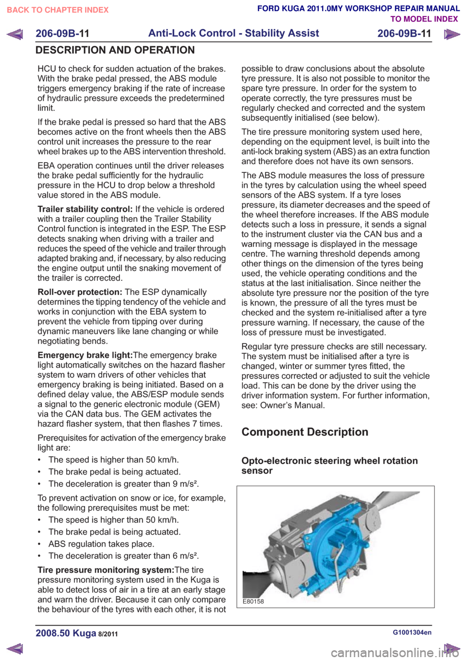
Component Description
Opto-electronic steering wheel rotation
sensor
E80158
G1001304en2008.50 Kuga8/2011
206-09B-
11
Anti-Lock Control - Stability Assist
206-09B- 11
DESCRIPTION AND OPERATION
TO MODEL INDEX
BACK TO CHAPTER INDEX
FORD KUGA 2011.0MY WORKSHOP REPAIR MANUAL
Page 1430 of 2057
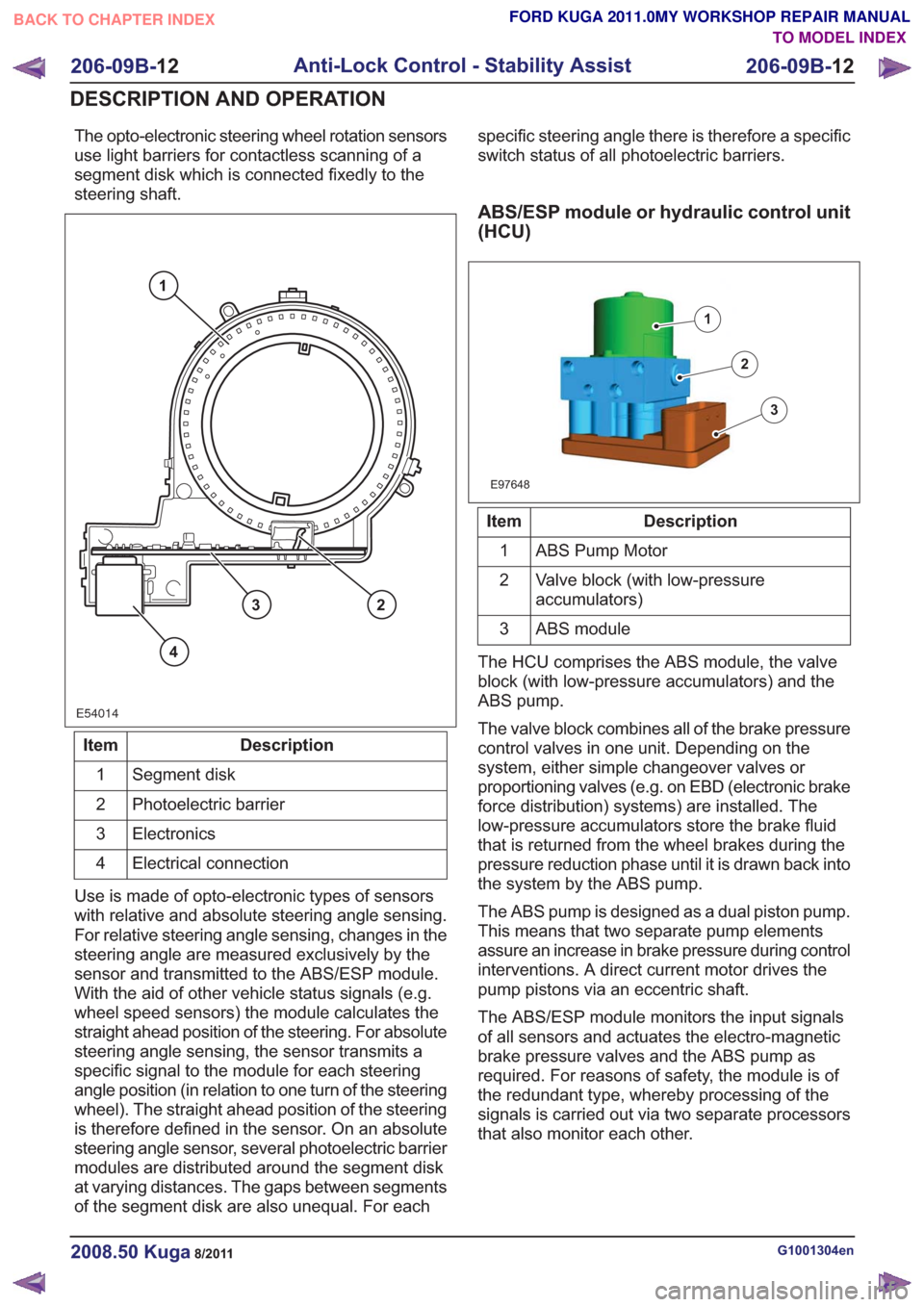
The opto-electronic steering wheel rotation sensors
use light barriers for contactless scanning of a
segment disk which is connected fixedly to the
steering shaft.
E54014
1
23
4
Description
Item
Segment disk
1
Photoelectric barrier
2
Electronics
3
Electrical connection
4
Use is made of opto-electronic types of sensors
with relative and absolute steering angle sensing.
For relative steering angle sensing, changes in the
steering angle are measured exclusively by the
sensor and transmitted to the ABS/ESP module.
With the aid of other vehicle status signals (e.g.
wheel speed sensors) the module calculates the
straight ahead position of the steering. For absolute
steering angle sensing, the sensor transmits a
specific signal to the module for each steering
angle position (in relation to one turn of the steering
wheel). The straight ahead position of the steering
is therefore defined in the sensor. On an absolute
steering angle sensor, several photoelectric barrier
modules are distributed around the segment disk
at varying distances. The gaps between segments
of the segment disk are also unequal. For each specific steering angle there is therefore a specific
switch status of all photoelectric barriers.
ABS/ESP module or hydraulic control unit
(HCU)
E97648
1
2
3
Description
Item
ABS Pump Motor
1
Valve block (with low-pressure
accumulators)
2
ABS module
3
The HCU comprises the ABS module, the valve
block (with low-pressure accumulators) and the
ABS pump.
The valve block combines all of the brake pressure
control valves in one unit. Depending on the
system, either simple changeover valves or
proportioning valves (e.g. on EBD (electronic brake
force distribution) systems) are installed. The
low-pressure accumulators store the brake fluid
that is returned from the wheel brakes during the
pressure reduction phase until it is drawn back into
the system by the ABS pump.
The ABS pump is designed as a dual piston pump.
This means that two separate pump elements
assure an increase in brake pressure during control
interventions. A direct current motor drives the
pump pistons via an eccentric shaft.
The ABS/ESP module monitors the input signals
of all sensors and actuates the electro-magnetic
brake pressure valves and the ABS pump as
required. For reasons of safety, the module is of
the redundant type, whereby processing of the
signals is carried out via two separate processors
that also monitor each other.
G1001304en2008.50 Kuga8/2011
206-09B- 12
Anti-Lock Control - Stability Assist
206-09B- 12
DESCRIPTION AND OPERATION
TO MODEL INDEX
BACK TO CHAPTER INDEX
FORD KUGA 2011.0MY WORKSHOP REPAIR MANUAL
Page 1434 of 2057
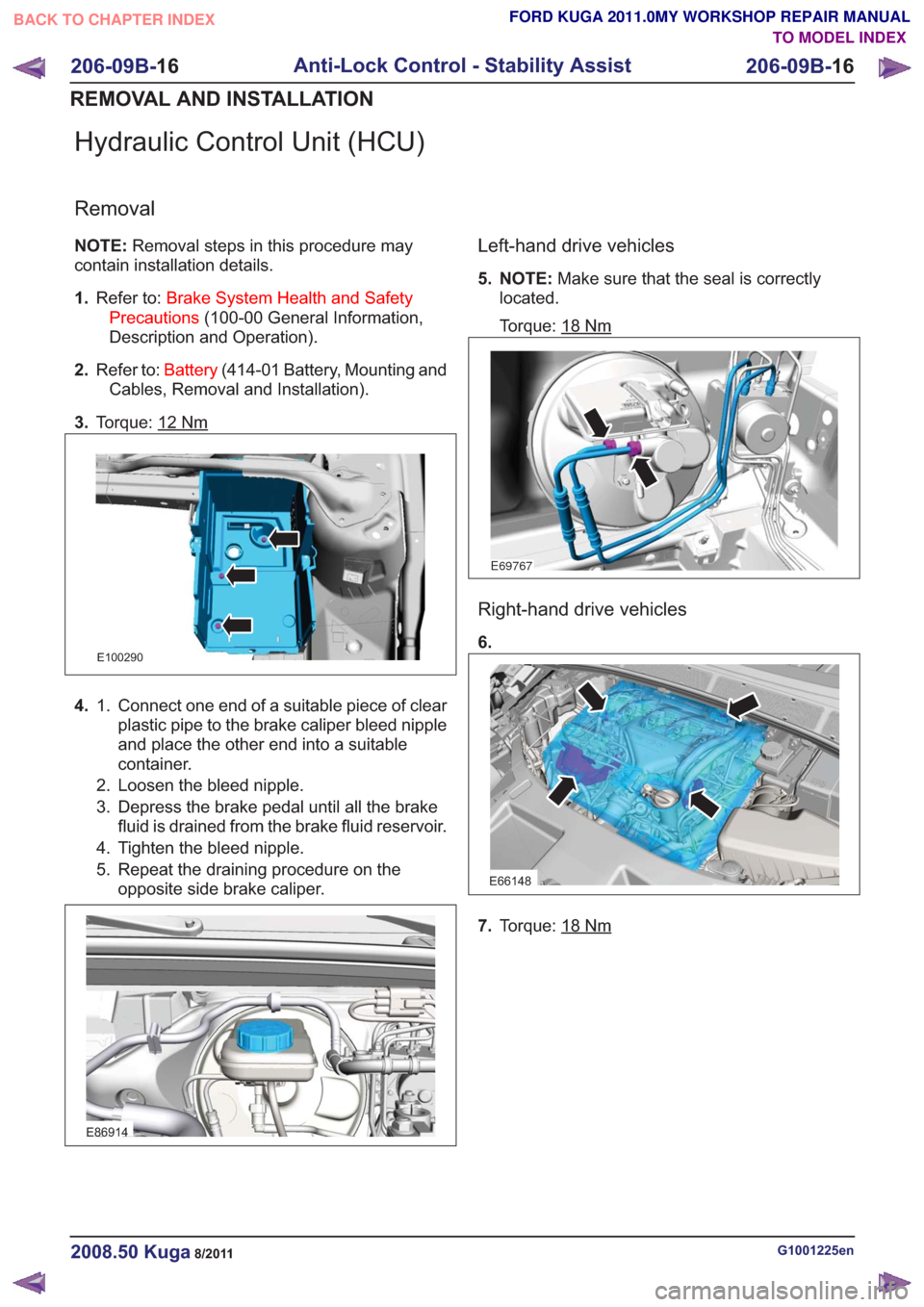
Hydraulic Control Unit (HCU)
Removal
NOTE:Removal steps in this procedure may
contain installation details.
1. Refer to: Brake System Health and Safety
Precautions (100-00 General Information,
Description and Operation).
2. Refer to: Battery(414-01 Battery, Mounting and
Cables, Removal and Installation).
3. Torque: 12
Nm
E100290
4. Connect one end of a suitable piece of clear
plastic pipe to the brake caliper bleed nipple
1.
and place the other end into a suitable
container.
2. Loosen the bleed nipple.
3. Depress the brake pedal until all the brake fluid is drained from the brake fluid reservoir.
4. Tighten the bleed nipple.
5. Repeat the draining procedure on the opposite side brake caliper.
E86914
Left-hand drive vehicles
5. NOTE: Make sure that the seal is correctly
located.
Torque: 18
Nm
E69767
Right-hand drive vehicles
6.
E66148
7. Torque: 18Nm
G1001225en2008.50 Kuga8/2011
206-09B- 16
Anti-Lock Control - Stability Assist
206-09B- 16
REMOVAL AND INSTALLATION
TO MODEL INDEX
BACK TO CHAPTER INDEX
FORD KUGA 2011.0MY WORKSHOP REPAIR MANUAL
Page 1436 of 2057
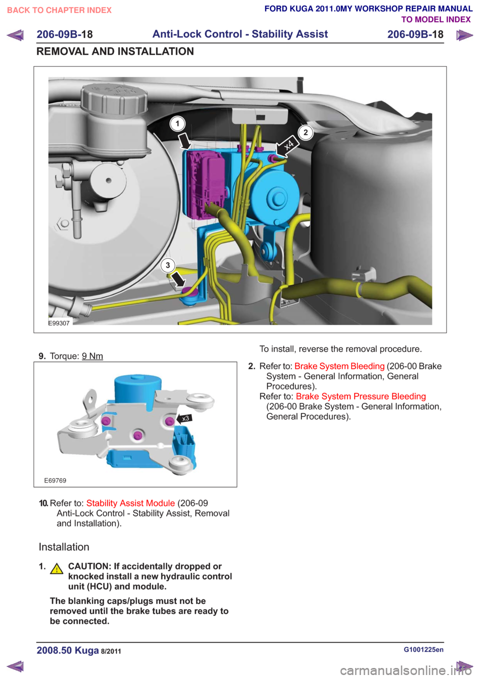
E99307
x4
1
2
3
9.Torque: 9Nm
E69769
x3
10.Refer to: Stability Assist Module (206-09
Anti-Lock Control - Stability Assist, Removal
and Installation).
Installation
1. CAUTION: If accidentally dropped or knocked install a new hydraulic control
unit (HCU) and module.
The blanking caps/plugs must not be
removed until the brake tubes are ready to
be connected. To install, reverse the removal procedure.
2. Refer to: Brake System Bleeding (206-00 Brake
System - General Information, General
Procedures).
Refer to: Brake System Pressure Bleeding
(206-00 Brake System - General Information,
General Procedures).
G1001225en2008.50 Kuga8/2011
206-09B- 18
Anti-Lock Control - Stability Assist
206-09B- 18
REMOVAL AND INSTALLATION
TO MODEL INDEX
BACK TO CHAPTER INDEX
FORD KUGA 2011.0MY WORKSHOP REPAIR MANUAL
Page 1835 of 2057
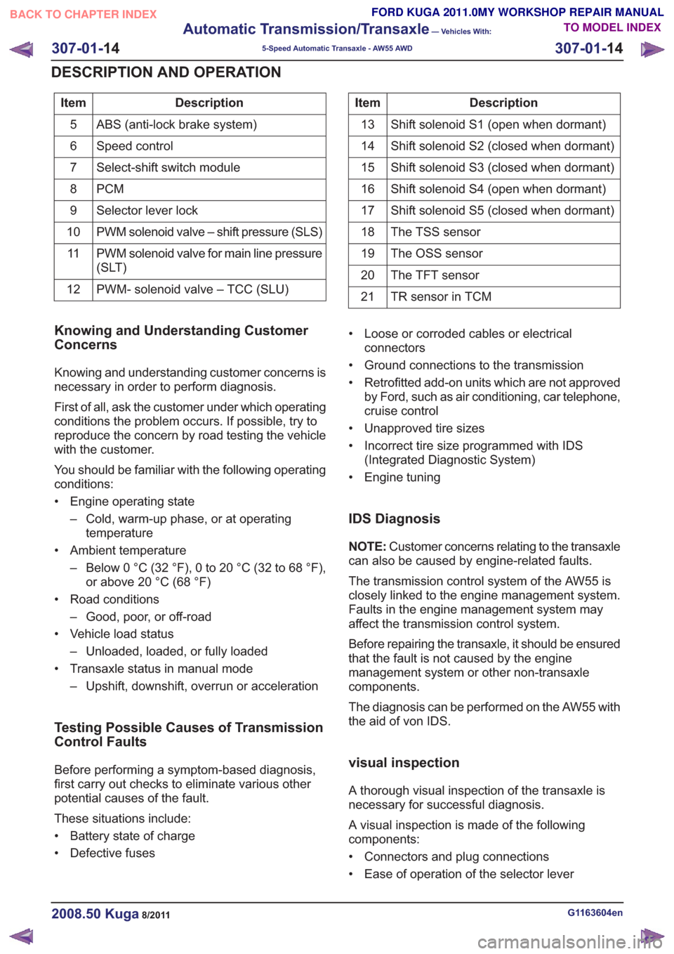
Description
Item
ABS (anti-lock brake system)
5
Speed control
6
Select-shift switch module
7
PCM
8
Selector lever lock
9
PWM solenoid valve – shift pressure (SLS)
10
PWM solenoid valve for main line pressure
(SLT)
11
PWM- solenoid valve – TCC (SLU)
12Description
Item
Shift solenoid S1 (open when dormant)
13
Shift solenoid S2 (closed when dormant)
14
Shift solenoid S3 (closed when dormant)
15
Shift solenoid S4 (open when dormant)
16
Shift solenoid S5 (closed when dormant)
17
The TSS sensor
18
The OSS sensor
19
The TFT sensor
20
TR sensor in TCM
21
Knowing and Understanding Customer
Concerns
Knowing and understanding customer concerns is
necessary in order to perform diagnosis.
First of all, ask the customer under which operating
conditions the problem occurs. If possible, try to
reproduce the concern by road testing the vehicle
with the customer.
You should be familiar with the following operating
conditions:
• Engine operating state
– Cold, warm-up phase, or at operatingtemperature
• Ambient temperature – Below 0 °C (32 °F), 0 to 20 °C (32 to 68 °F),or above 20 °C (68 °F)
• Road conditions – Good, poor, or off-road
• Vehicle load status – Unloaded, loaded, or fully loaded
• Transaxle status in manual mode – Upshift, downshift, overrun or acceleration
Testing Possible Causes of Transmission
Control Faults
Before performing a symptom-based diagnosis,
first carry out checks to eliminate various other
potential causes of the fault.
These situations include:
• Battery state of charge
• Defective fuses • Loose or corroded cables or electrical
connectors
• Ground connections to the transmission
• Retrofitted add-on units which are not approved by Ford, such as air conditioning, car telephone,
cruise control
• Unapproved tire sizes
• Incorrect tire size programmed with IDS (Integrated Diagnostic System)
• Engine tuning
IDS Diagnosis
NOTE: Customer concerns relating to the transaxle
can also be caused by engine-related faults.
The transmission control system of the AW55 is
closely linked to the engine management system.
Faults in the engine management system may
affect the transmission control system.
Before repairing the transaxle, it should be ensured
that the fault is not caused by the engine
management system or other non-transaxle
components.
The diagnosis can be performed on the AW55 with
the aid of von IDS.
visual inspection
A thorough visual inspection of the transaxle is
necessary for successful diagnosis.
A visual inspection is made of the following
components:
• Connectors and plug connections
• Ease of operation of the selector lever
G1163604en2008.50 Kuga8/2011
307-01- 14
Automatic Transmission/Transaxle
— Vehicles With:
5-Speed Automatic Transaxle - AW55 AWD
307-01- 14
DESCRIPTION AND OPERATION
TO MODEL INDEX
BACK TO CHAPTER INDEX
FORD KUGA 2011.0MY WORKSHOP REPAIR MANUAL
Page 2006 of 2057
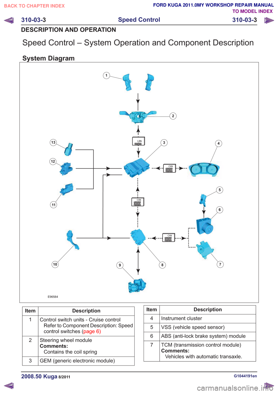
Speed Control – System Operation and Component Description
System Diagram
E96584
1
2
34
6
78910
11
12
13
5
Description
Item
Control switch units - Cruise controlRefer to Component Description: Speed
controlswitches(page6)
1
Steering wheel module
Comments:Contains the coil spring
2
GEM (generic electronic module)
3Description
Item
Instrument cluster
4
VSS (vehicle speed sensor)
5
ABS (anti-lock brake system) module
6
TCM (transmission control module)
Comments:Vehicles with automatic transaxle.
7
G1044191en2008.50 Kuga8/2011
310-03-
3
Speed Control
310-03- 3
DESCRIPTION AND OPERATION
TO MODEL INDEX
BACK TO CHAPTER INDEX
FORD KUGA 2011.0MY WORKSHOP REPAIR MANUAL