2011 FORD KUGA Anti Lock Brake System
[x] Cancel search: Anti Lock Brake SystemPage 1342 of 2057
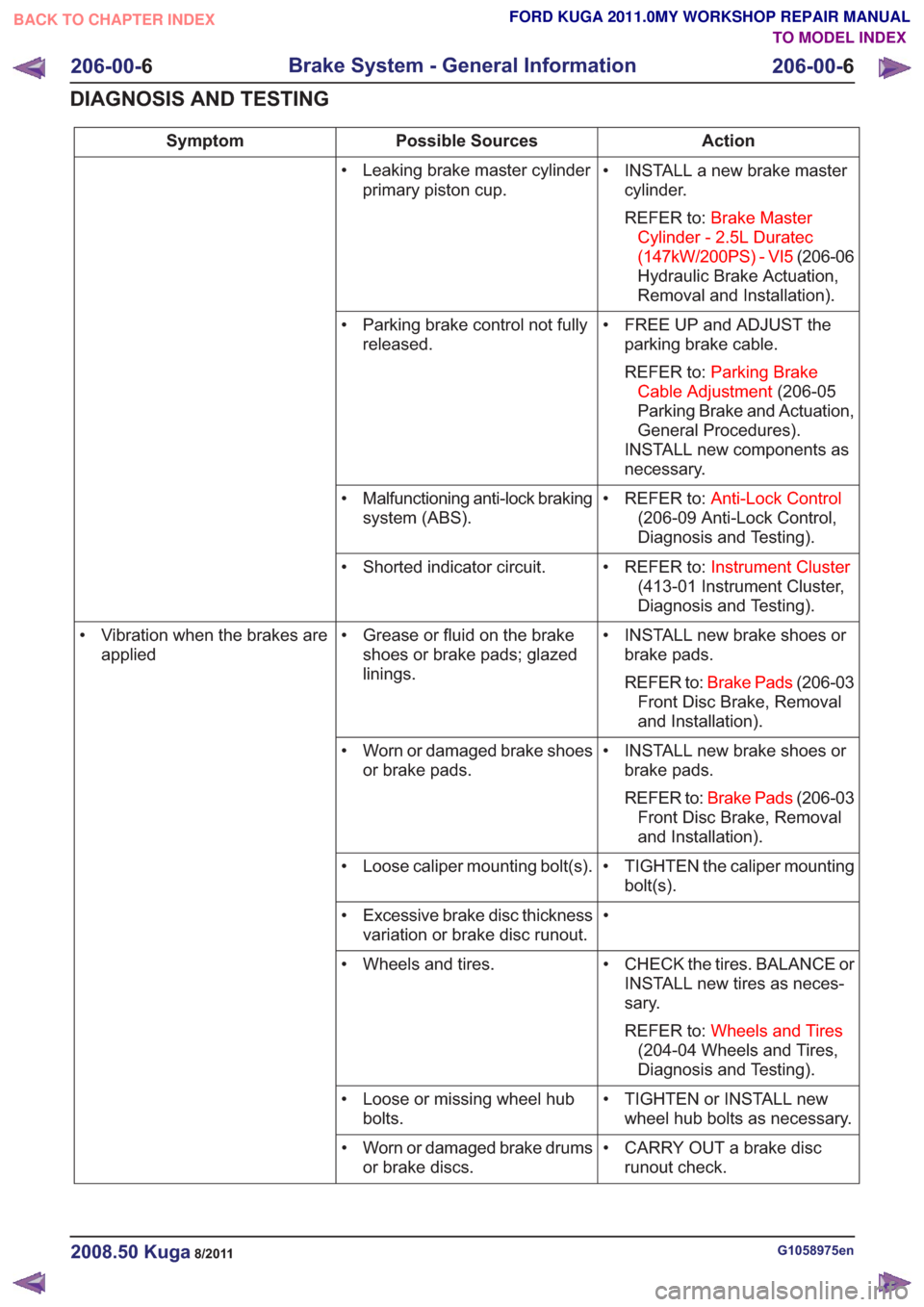
Action
Possible Sources
Symptom
• INSTALL a new brake mastercylinder.
REFER to: Brake Master
Cylinder - 2.5L Duratec
(147kW/200PS) - VI5 (206-06
Hydraulic Brake Actuation,
Removal and Installation).
• Leaking brake master cylinder
primary piston cup.
• FREE UP and ADJUST theparking brake cable.
REFER to: Parking Brake
Cable Adjustment (206-05
Parking Brake and Actuation,
General Procedures).
INSTALL new components as
necessary.
• Parking brake control not fully
released.
• REFER to:Anti-Lock Control
(206-09 Anti-Lock Control,
Diagnosis and Testing).
• Malfunctioning anti-lock braking
system (ABS).
• REFER to:Instrument Cluster
(413-01 Instrument Cluster,
Diagnosis and Testing).
• Shorted indicator circuit.
• INSTALL new brake shoes orbrake pads.
REFER to: Brake Pads (206-03
Front Disc Brake, Removal
and Installation).
• Grease or fluid on the brake
shoes or brake pads; glazed
linings.
• Vibration when the brakes are
applied
• INSTALL new brake shoes orbrake pads.
REFER to: Brake Pads (206-03
Front Disc Brake, Removal
and Installation).
• Worn or damaged brake shoes
or brake pads.
• TIGHTEN the caliper mountingbolt(s).
• Loose caliper mounting bolt(s).
•
• Excessive brake disc thickness
variation or brake disc runout.
• CHECK the tires. BALANCE orINSTALL new tires as neces-
sary.
REFER to: Wheels and Tires
(204-04 Wheels and Tires,
Diagnosis and Testing).
• Wheels and tires.
• TIGHTEN or INSTALL newwheel hub bolts as necessary.
• Loose or missing wheel hub
bolts.
• CARRY OUT a brake discrunout check.
• Worn or damaged brake drums
or brake discs.
G1058975en2008.50 Kuga8/2011
206-00- 6
Brake System - General Information
206-00- 6
DIAGNOSIS AND TESTING
TO MODEL INDEX
BACK TO CHAPTER INDEX
FORD KUGA 2011.0MY WORKSHOP REPAIR MANUAL
Page 1414 of 2057
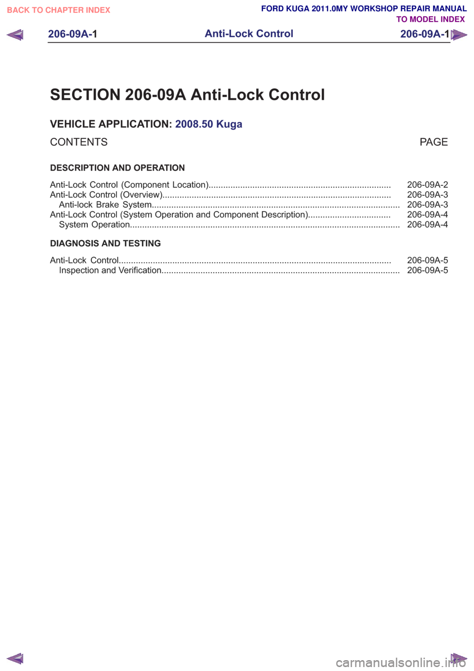
SECTION 206-09A Anti-Lock Control
VEHICLE APPLICATION:2008.50 Kuga
PA G E
CONTENTS
DESCRIPTION AND OPERATION
206-09A-2
Anti-Lock Control (Component Location) ........................................................................\
...
206-09A-3
Anti-Lock Control (Overview) ........................................................................\
......................
206-09A-3
Anti-lock Brake System ........................................................................\
..............................
206-09A-4
Anti-Lock Control (System Operation and Component Description) ..................................
206-09A-4
System Operation ........................................................................\
.......................................
DIAGNOSIS AND TESTING 206-09A-5
Anti-Lock Control ........................................................................\
........................................
206-09A-5
Inspection and Verification ........................................................................\
..........................
206-09A-1
Anti-Lock Control
206-09A- 1
.
TO MODEL INDEX
BACK TO CHAPTER INDEX
FORD KUGA 2011.0MY WORKSHOP REPAIR MANUAL
Page 1415 of 2057
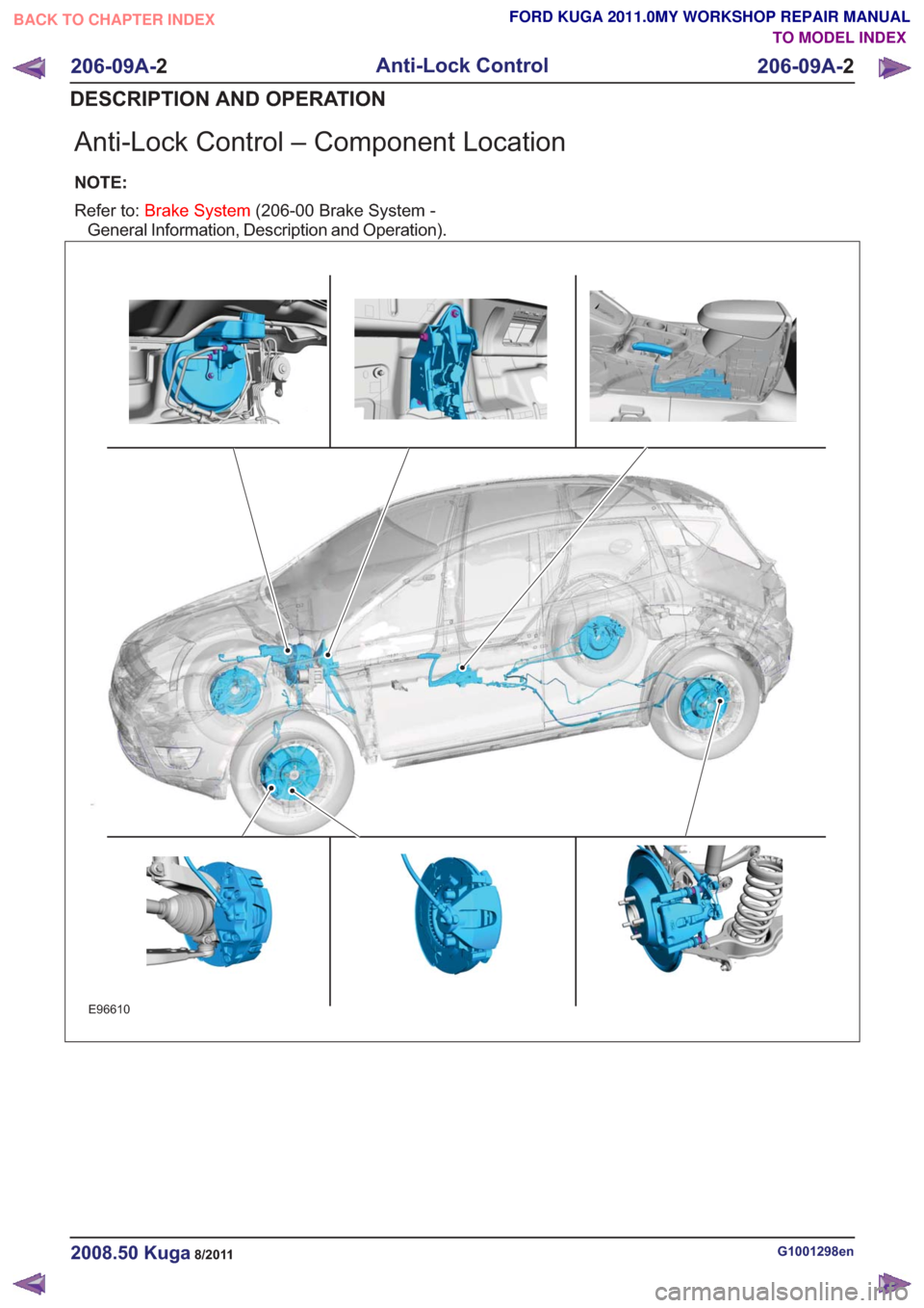
Anti-Lock Control – Component Location
NOTE:
Refer to:Brake System (206-00 Brake System -
General Information, Description and Operation).
E96610
G1001298en2008.50 Kuga8/2011
206-09A- 2
Anti-Lock Control
206-09A- 2
DESCRIPTION AND OPERATION
TO MODEL INDEX
BACK TO CHAPTER INDEX
FORD KUGA 2011.0MY WORKSHOP REPAIR MANUAL
Page 1416 of 2057
Anti-Lock Control – Overview
Anti-lock Brake System
Refer to:Anti-Lock Control - Stability Assist (206-09
Anti-Lock Control - Stability Assist, Description
and Operation).
G1001218en2008.50 Kuga8/2011
206-09A- 3
Anti-Lock Control
206-09A- 3
DESCRIPTION AND OPERATION
TO MODEL INDEX
BACK TO CHAPTER INDEX
FORD KUGA 2011.0MY WORKSHOP REPAIR MANUAL
Page 1418 of 2057
Anti-Lock Control
schematic
and connector information.
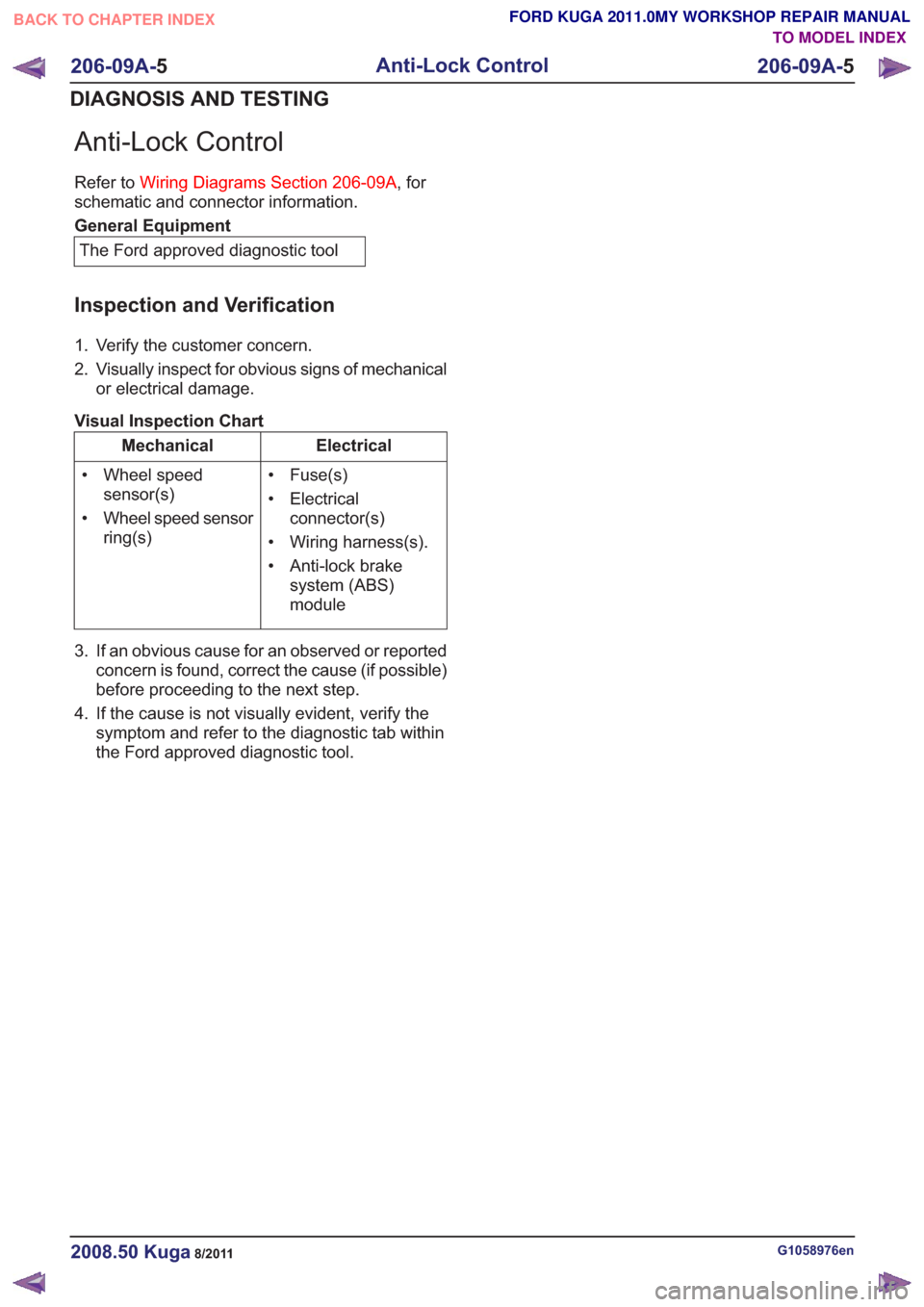
General Equipment
The Ford approved diagnostic tool
Inspection and Verification
1. Verify the customer concern.
2. Visually inspect for obvious signs of mechanical or electrical damage.
Visual Inspection Chart
Electrical
Mechanical
• Fuse(s)
• Electricalconnector(s)
• Wiring harness(s).
• Anti-lock brake system (ABS)
module
• Wheel speed
sensor(s)
• Wheel speed sensor ring(s)
3. If an obvious cause for an observed or reported concern is found, correct the cause (if possible)
before proceeding to the next step.
4. If the cause is not visually evident, verify the symptom and refer to the diagnostic tab within
the Ford approved diagnostic tool.
G1058976en2008.50 Kuga8/2011
206-09A- 5
Anti-Lock Control
206-09A- 5
DIAGNOSIS AND TESTING
TO MODEL INDEX
BACK TO CHAPTER INDEX
FORD KUGA 2011.0MY WORKSHOP REPAIR MANUAL
Refer to
Wiring Diagrams Section 206-09A, for
Page 1419 of 2057
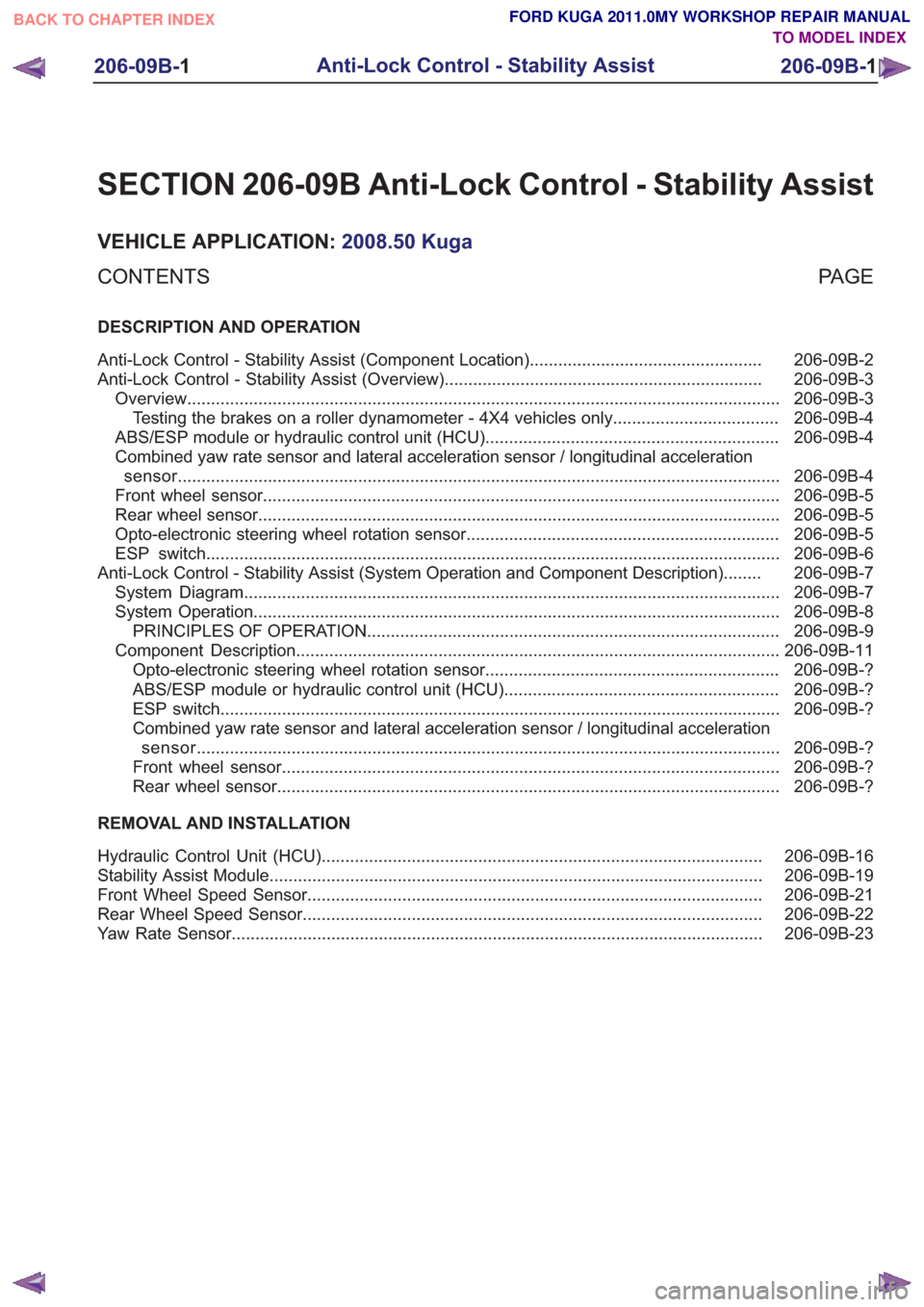
SECTION 206-09B Anti-Lock Control - Stability Assist
VEHICLE APPLICATION:2008.50 Kuga
PA G E
CONTENTS
DESCRIPTION AND OPERATION
206-09B-2
Anti-Lock Control - Stability Assist (Component Location) .................................................
206-09B-3
Anti-Lock Control - Stability Assist (Overview) ...................................................................
206-09B-3
Overview ........................................................................\
.....................................................
206-09B-4
Testing the brakes on a roller dynamometer - 4X4 vehicles only ...................................
206-09B-4
ABS/ESP module or hydraulic control unit (HCU) ..............................................................
206-09B-4
Combined yaw rate sensor and lateral acceleration sensor / longitudinal acceleration
sensor ........................................................................\
.......................................................
206-09B-5
Front wheel sensor ........................................................................\
.....................................
206-09B-5
Rear wheel sensor ........................................................................\
......................................
206-09B-5
Opto-electronic steering wheel rotation sensor ..................................................................
206-09B-6
ESP switch ........................................................................\
.................................................
206-09B-7
Anti-Lock Control - Stability Assist (System Operation and Component Description) ........
206-09B-7
System Diagram ........................................................................\
.........................................
206-09B-8
System Operation ........................................................................\
.......................................
206-09B-9
PRINCIPLES OF OPERATION ........................................................................\
...............
206-09B-11
Component Description ........................................................................\
..............................
206-09B-?
Opto-electronic steering wheel rotation sensor ..............................................................
206-09B-?
ABS/ESP module or hydraulic control unit (HCU) ..........................................................
206-09B-?
ESP switch ........................................................................\
..............................................
206-09B-?
Combined yaw rate sensor and lateral acceleration sensor / longitudinal acceleration
sensor........................................................................\
................................................... 206-09B-?
Front wheel sensor ........................................................................\
.................................
206-09B-?
Rear wheel sensor ........................................................................\
..................................
REMOVAL AND INSTALLATION 206-09B-16
Hydraulic Control Unit (HCU) ........................................................................\
.....................
206-09B-19
Stability Assist Module ........................................................................\
................................
206-09B-21
Front Wheel Speed Sensor ........................................................................\
........................
206-09B-22
Rear Wheel Speed Sensor ........................................................................\
.........................
206-09B-23
Yaw Rate Sensor ........................................................................\
........................................
206-09B-1
Anti-Lock Control - Stability Assist
206-09B- 1
.
TO MODEL INDEX
BACK TO CHAPTER INDEX
FORD KUGA 2011.0MY WORKSHOP REPAIR MANUAL
Page 1422 of 2057
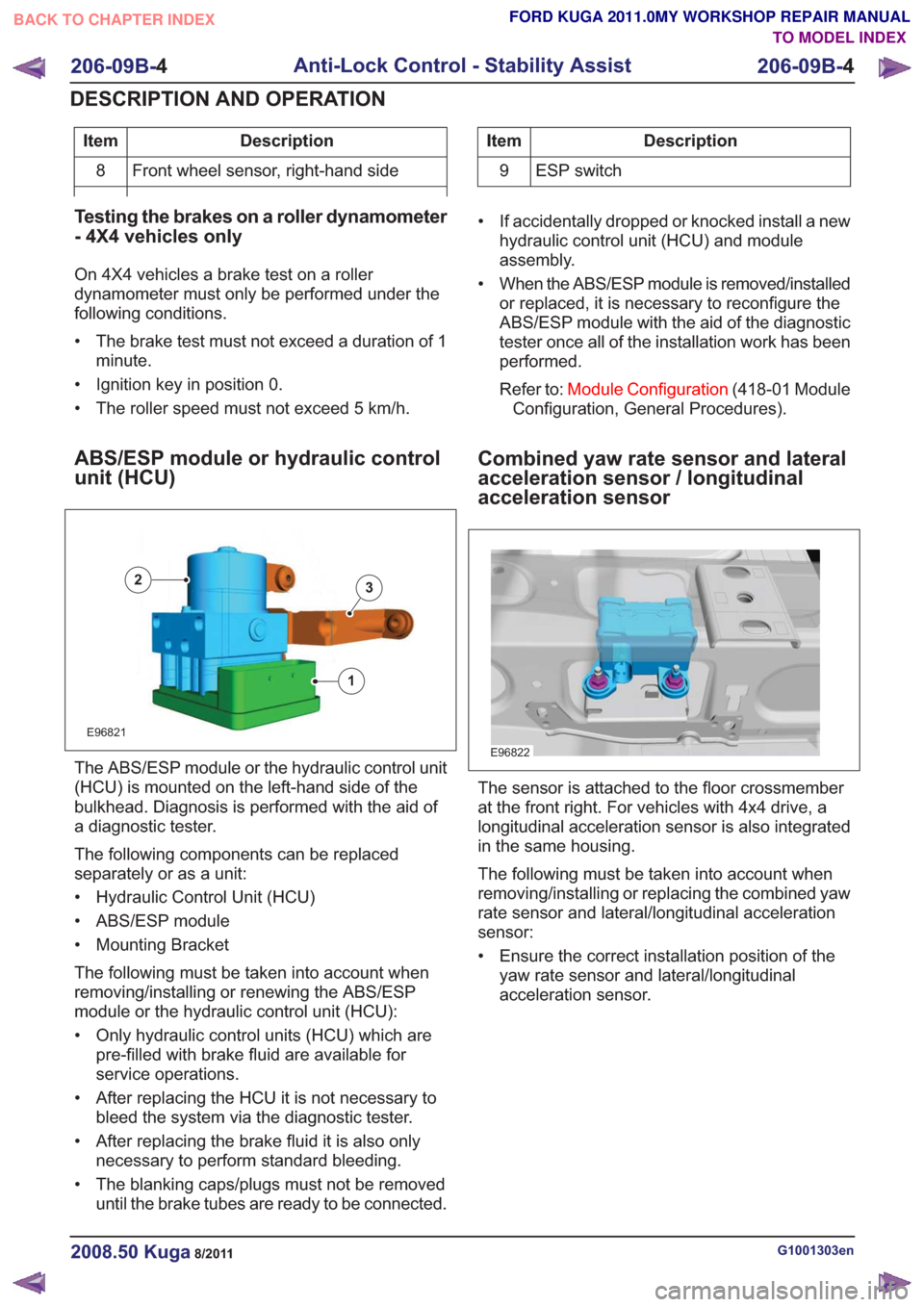
Description
Item
Front wheel sensor, right-hand side
8Description
Item
9 ESP switch
Testing the brakes on a roller dynamometer
- 4X4 vehicles only
On 4X4 vehicles a brake test on a roller
dynamometer must only be performed under the
following conditions.
• The brake test must not exceed a duration of 1 minute.
• Ignition key in position 0.
• The roller speed must not exceed 5 km/h.
ABS/ESP module or hydraulic control
unit (HCU)
E96821
1
23
The ABS/ESP module or the hydraulic control unit
(HCU) is mounted on the left-hand side of the
bulkhead. Diagnosis is performed with the aid of
a diagnostic tester.
The following components can be replaced
separately or as a unit:
• Hydraulic Control Unit (HCU)
• ABS/ESP module
• Mounting Bracket
The following must be taken into account when
removing/installing or renewing the ABS/ESP
module or the hydraulic control unit (HCU):
• Only hydraulic control units (HCU) which are pre-filled with brake fluid are available for
service operations.
• After replacing the HCU it is not necessary to bleed the system via the diagnostic tester.
• After replacing the brake fluid it is also only necessary to perform standard bleeding.
• The blanking caps/plugs must not be removed until the brake tubes are ready to be connected. • If accidentally dropped or knocked install a new
hydraulic control unit (HCU) and module
assembly.
• When the ABS/ESP module is removed/installed or replaced, it is necessary to reconfigure the
ABS/ESP module with the aid of the diagnostic
tester once all of the installation work has been
performed.
Refer to: Module Configuration (418-01 Module
Configuration, General Procedures).
Combined yaw rate sensor and lateral
acceleration sensor / longitudinal
acceleration sensor
E96822
The sensor is attached to the floor crossmember
at the front right. For vehicles with 4x4 drive, a
longitudinal acceleration sensor is also integrated
in the same housing.
The following must be taken into account when
removing/installing or replacing the combined yaw
rate sensor and lateral/longitudinal acceleration
sensor:
• Ensure the correct installation position of the yaw rate sensor and lateral/longitudinal
acceleration sensor.
G1001303en2008.50 Kuga8/2011
206-09B- 4
Anti-Lock Control - Stability Assist
206-09B- 4
DESCRIPTION AND OPERATION
TO MODEL INDEX
BACK TO CHAPTER INDEX
FORD KUGA 2011.0MY WORKSHOP REPAIR MANUAL
Page 1425 of 2057
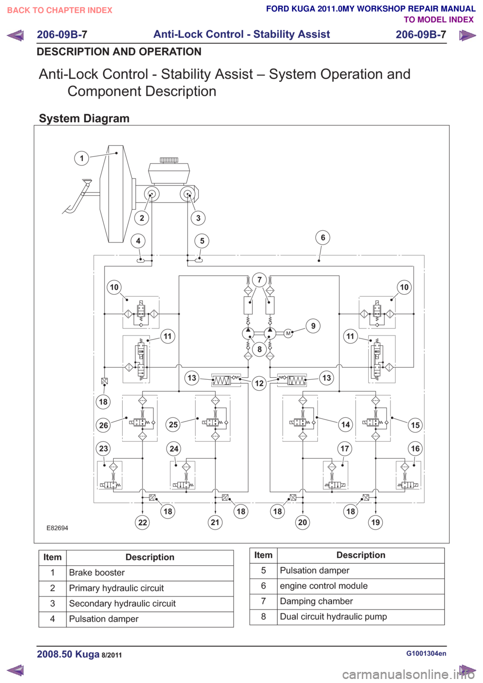
Anti-Lock Control - Stability Assist – System Operation andComponent Description
System Diagram
E82694
M
P
UP
U
P
U
P
U
P
U
1
10
22
23
456
7
8
9
11
1213
1415
1617
18
2324
13
11
10
19
2526
2120
181818
18
Description
Item
Brake booster
1
Primary hydraulic circuit
2
Secondary hydraulic circuit
3
Pulsation damper
4Description
Item
Pulsation damper
5
engine control module
6
Damping chamber
7
Dual circuit hydraulic pump
8
G1001304en2008.50 Kuga8/2011
206-09B- 7
Anti-Lock Control - Stability Assist
206-09B- 7
DESCRIPTION AND OPERATION
TO MODEL INDEX
BACK TO CHAPTER INDEX
FORD KUGA 2011.0MY WORKSHOP REPAIR MANUAL