2011 FORD KUGA engine mount
[x] Cancel search: engine mountPage 1299 of 2057
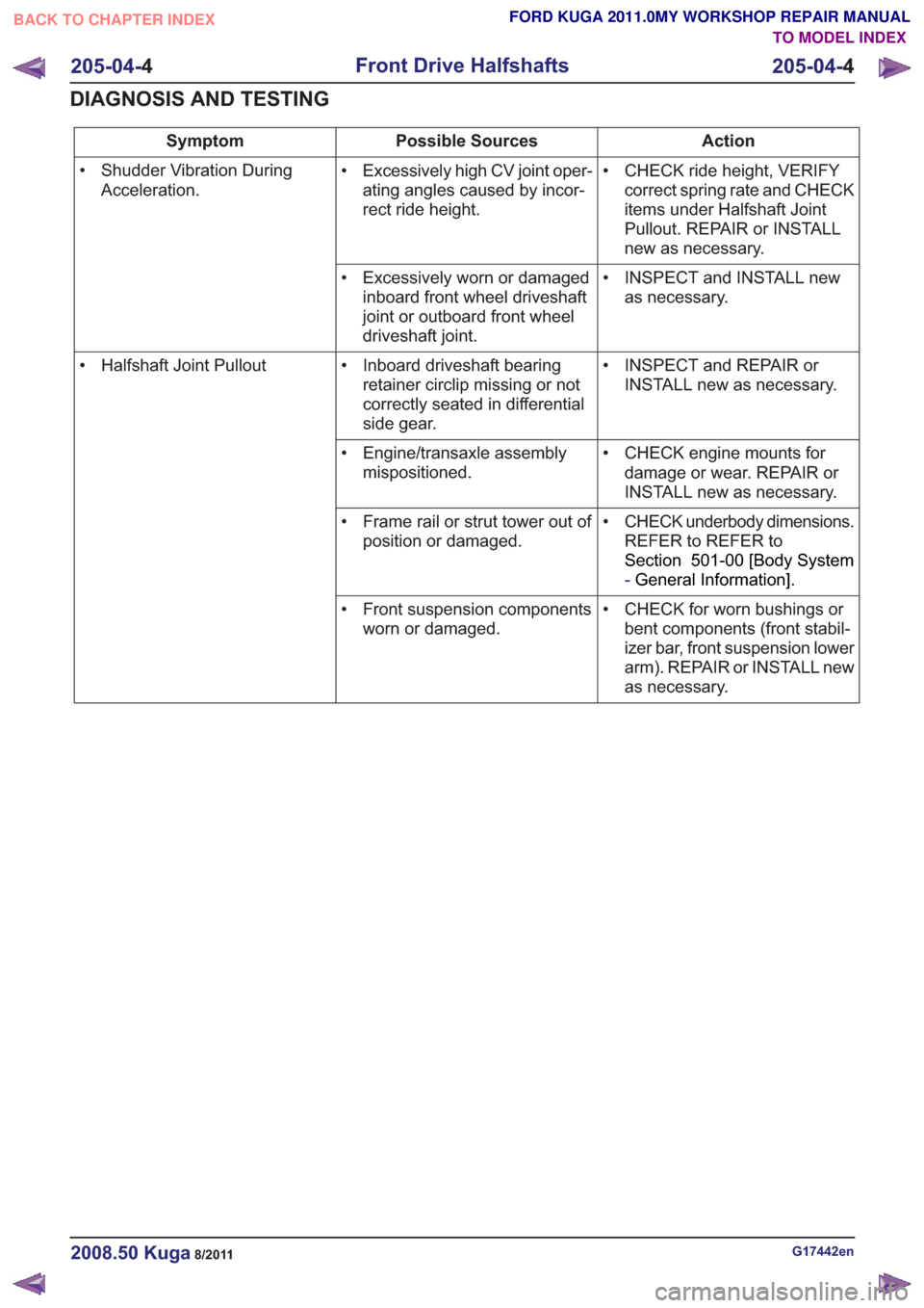
Action
Possible Sources
Symptom
• CHECK ride height, VERIFYcorrect spring rate and CHECK
items under Halfshaft Joint
Pullout. REPAIR or INSTALL
new as necessary.
• Excessively high CV joint oper-
ating angles caused by incor-
rect ride height.
• Shudder Vibration During
Acceleration.
• INSPECT and INSTALL newas necessary.
• Excessively worn or damaged
inboard front wheel driveshaft
joint or outboard front wheel
driveshaft joint.
• INSPECT and REPAIR orINSTALL new as necessary.
• Inboard driveshaft bearing
retainer circlip missing or not
correctly seated in differential
side gear.
• Halfshaft Joint Pullout
• CHECK engine mounts fordamage or wear. REPAIR or
INSTALL new as necessary.
• Engine/transaxle assembly
mispositioned.
• CHECK underbody dimensions.REFER to REFER to
Section 501-00 [Body System
-General Information] .
• Frame rail or strut tower out of
position or damaged.
• CHECK for worn bushings orbent components (front stabil-
izer bar, front suspension lower
arm). REPAIR or INSTALL new
as necessary.
• Front suspension components
worn or damaged.
G17442en2008.50 Kuga8/2011
205-04- 4
Front Drive Halfshafts
205-04- 4
DIAGNOSIS AND TESTING
TO MODEL INDEX
BACK TO CHAPTER INDEX
FORD KUGA 2011.0MY WORKSHOP REPAIR MANUAL
Page 1354 of 2057
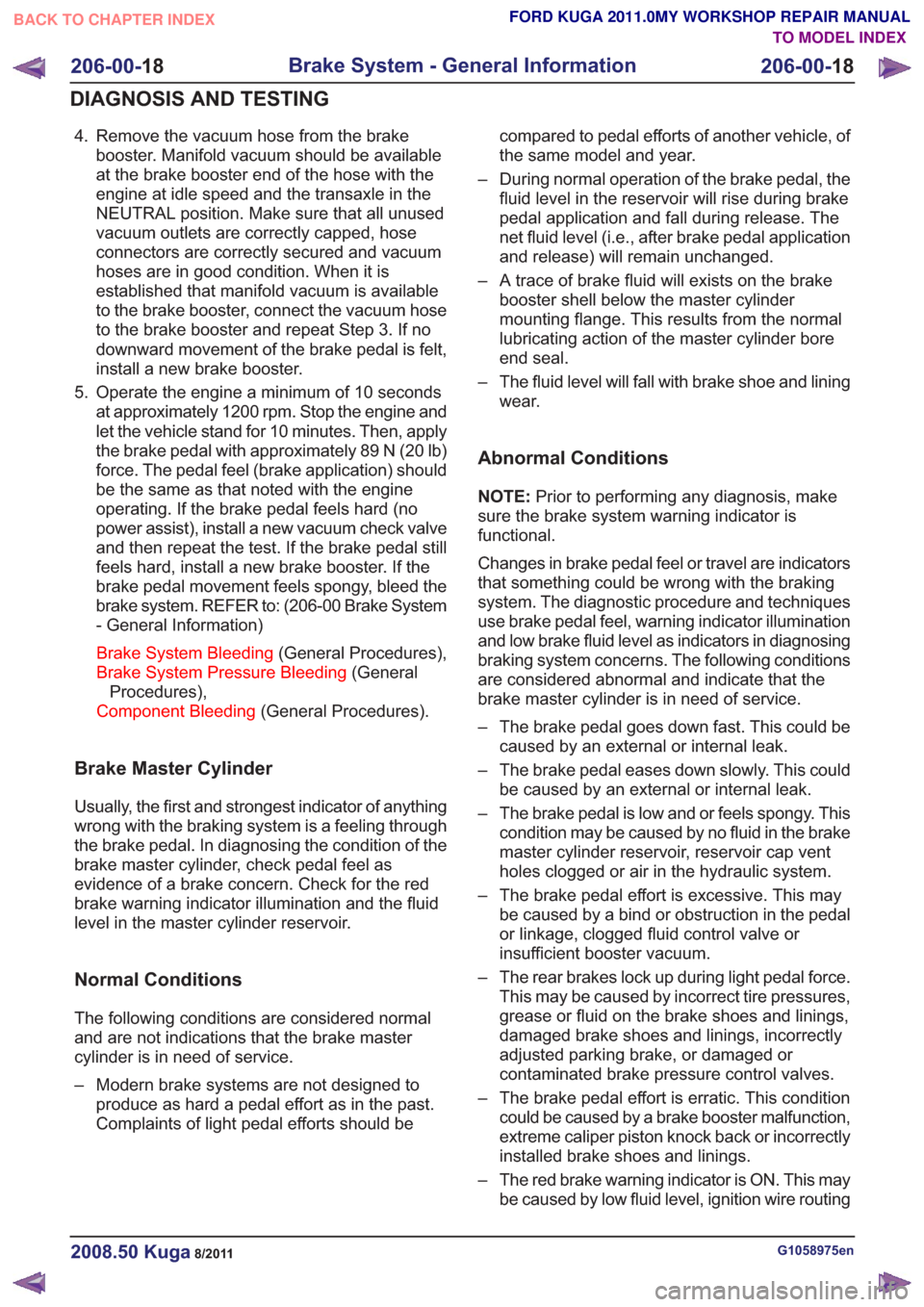
4. Remove the vacuum hose from the brakebooster. Manifold vacuum should be available
at the brake booster end of the hose with the
engine at idle speed and the transaxle in the
NEUTRAL position. Make sure that all unused
vacuum outlets are correctly capped, hose
connectors are correctly secured and vacuum
hoses are in good condition. When it is
established that manifold vacuum is available
to the brake booster, connect the vacuum hose
to the brake booster and repeat Step 3. If no
downward movement of the brake pedal is felt,
install a new brake booster.
5. Operate the engine a minimum of 10 seconds at approximately 1200 rpm. Stop the engine and
let the vehicle stand for 10 minutes. Then, apply
the brake pedal with approximately 89 N (20 lb)
force. The pedal feel (brake application) should
be the same as that noted with the engine
operating. If the brake pedal feels hard (no
power assist), install a new vacuum check valve
and then repeat the test. If the brake pedal still
feels hard, install a new brake booster. If the
brake pedal movement feels spongy, bleed the
brake system. REFER to: (206-00 Brake System
- General Information)
Brake System Bleeding (General Procedures),
Brake System Pressure Bleeding (General
Procedures),
Component Bleeding (General Procedures).
Brake Master Cylinder
Usually, the first and strongest indicator of anything
wrong with the braking system is a feeling through
the brake pedal. In diagnosing the condition of the
brake master cylinder, check pedal feel as
evidence of a brake concern. Check for the red
brake warning indicator illumination and the fluid
level in the master cylinder reservoir.
Normal Conditions
The following conditions are considered normal
and are not indications that the brake master
cylinder is in need of service.
– Modern brake systems are not designed to
produce as hard a pedal effort as in the past.
Complaints of light pedal efforts should be compared to pedal efforts of another vehicle, of
the same model and year.
– During normal operation of the brake pedal, the fluid level in the reservoir will rise during brake
pedal application and fall during release. The
net fluid level (i.e., after brake pedal application
and release) will remain unchanged.
– A trace of brake fluid will exists on the brake booster shell below the master cylinder
mounting flange. This results from the normal
lubricating action of the master cylinder bore
end seal.
– The fluid level will fall with brake shoe and lining wear.
Abnormal Conditions
NOTE: Prior to performing any diagnosis, make
sure the brake system warning indicator is
functional.
Changes in brake pedal feel or travel are indicators
that something could be wrong with the braking
system. The diagnostic procedure and techniques
use brake pedal feel, warning indicator illumination
and low brake fluid level as indicators in diagnosing
braking system concerns. The following conditions
are considered abnormal and indicate that the
brake master cylinder is in need of service.
– The brake pedal goes down fast. This could be caused by an external or internal leak.
– The brake pedal eases down slowly. This could be caused by an external or internal leak.
– The brake pedal is low and or feels spongy. This condition may be caused by no fluid in the brake
master cylinder reservoir, reservoir cap vent
holes clogged or air in the hydraulic system.
– The brake pedal effort is excessive. This may be caused by a bind or obstruction in the pedal
or linkage, clogged fluid control valve or
insufficient booster vacuum.
– The rear brakes lock up during light pedal force. This may be caused by incorrect tire pressures,
grease or fluid on the brake shoes and linings,
damaged brake shoes and linings, incorrectly
adjusted parking brake, or damaged or
contaminated brake pressure control valves.
– The brake pedal effort is erratic. This condition could be caused by a brake booster malfunction,
extreme caliper piston knock back or incorrectly
installed brake shoes and linings.
– The red brake warning indicator is ON. This may be caused by low fluid level, ignition wire routing
G1058975en2008.50 Kuga8/2011
206-00- 18
Brake System - General Information
206-00- 18
DIAGNOSIS AND TESTING
TO MODEL INDEX
BACK TO CHAPTER INDEX
FORD KUGA 2011.0MY WORKSHOP REPAIR MANUAL
Page 1428 of 2057
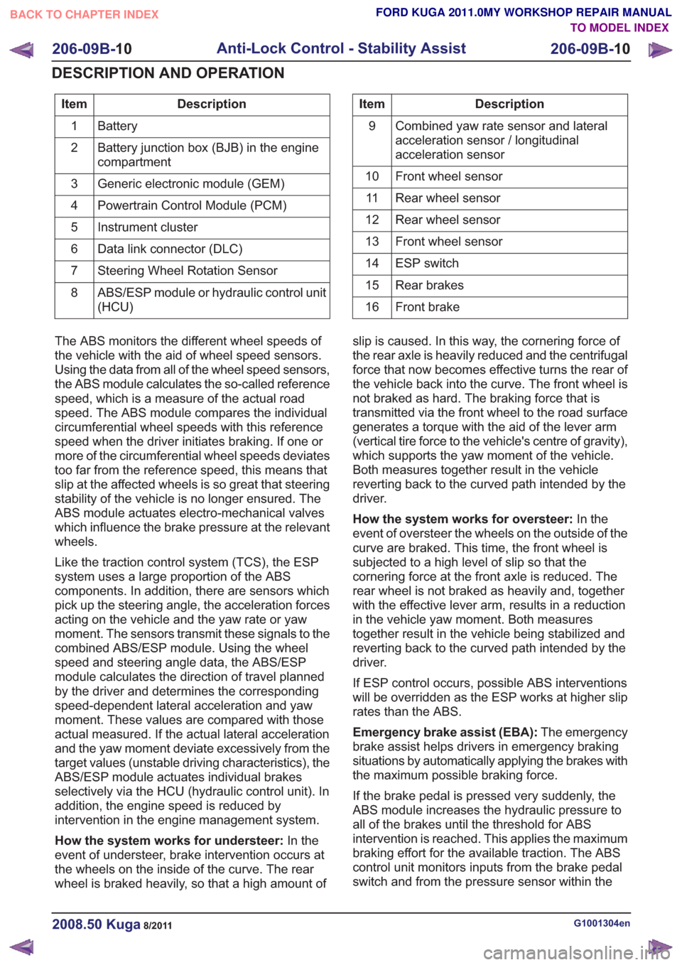
Description
Item
Battery
1
Battery junction box (BJB) in the engine
compartment
2
Generic electronic module (GEM)
3
Powertrain Control Module (PCM)
4
Instrument cluster
5
Data link connector (DLC)
6
Steering Wheel Rotation Sensor
7
ABS/ESP module or hydraulic control unit
(HCU)
8Description
Item
Combined yaw rate sensor and lateral
acceleration sensor / longitudinal
acceleration sensor
9
Front wheel sensor
10
Rear wheel sensor
11
Rear wheel sensor
12
Front wheel sensor
13
ESP switch
14
Rear brakes
15
Front brake
16
The ABS monitors the different wheel speeds of
the vehicle with the aid of wheel speed sensors.
Using the data from all of the wheel speed sensors,
the ABS module calculates the so-called reference
speed, which is a measure of the actual road
speed. The ABS module compares the individual
circumferential wheel speeds with this reference
speed when the driver initiates braking. If one or
more of the circumferential wheel speeds deviates
too far from the reference speed, this means that
slip at the affected wheels is so great that steering
stability of the vehicle is no longer ensured. The
ABS module actuates electro-mechanical valves
which influence the brake pressure at the relevant
wheels.
Like the traction control system (TCS), the ESP
system uses a large proportion of the ABS
components. In addition, there are sensors which
pick up the steering angle, the acceleration forces
acting on the vehicle and the yaw rate or yaw
moment. The sensors transmit these signals to the
combined ABS/ESP module. Using the wheel
speed and steering angle data, the ABS/ESP
module calculates the direction of travel planned
by the driver and determines the corresponding
speed-dependent lateral acceleration and yaw
moment. These values are compared with those
actual measured. If the actual lateral acceleration
and the yaw moment deviate excessively from the
target values (unstable driving characteristics), the
ABS/ESP module actuates individual brakes
selectively via the HCU (hydraulic control unit). In
addition, the engine speed is reduced by
intervention in the engine management system.
How the system works for understeer: In the
event of understeer, brake intervention occurs at
the wheels on the inside of the curve. The rear
wheel is braked heavily, so that a high amount of slip is caused. In this way, the cornering force of
the rear axle is heavily reduced and the centrifugal
force that now becomes effective turns the rear of
the vehicle back into the curve. The front wheel is
not braked as hard. The braking force that is
transmitted via the front wheel to the road surface
generates a torque with the aid of the lever arm
(vertical tire force to the vehicle's centre of gravity),
which supports the yaw moment of the vehicle.
Both measures together result in the vehicle
reverting back to the curved path intended by the
driver.
How the system works for oversteer:
In the
event of oversteer the wheels on the outside of the
curve are braked. This time, the front wheel is
subjected to a high level of slip so that the
cornering force at the front axle is reduced. The
rear wheel is not braked as heavily and, together
with the effective lever arm, results in a reduction
in the vehicle yaw moment. Both measures
together result in the vehicle being stabilized and
reverting back to the curved path intended by the
driver.
If ESP control occurs, possible ABS interventions
will be overridden as the ESP works at higher slip
rates than the ABS.
Emergency brake assist (EBA): The emergency
brake assist helps drivers in emergency braking
situations by automatically applying the brakes with
the maximum possible braking force.
If the brake pedal is pressed very suddenly, the
ABS module increases the hydraulic pressure to
all of the brakes until the threshold for ABS
intervention is reached. This applies the maximum
braking effort for the available traction. The ABS
control unit monitors inputs from the brake pedal
switch and from the pressure sensor within the
G1001304en2008.50 Kuga8/2011
206-09B- 10
Anti-Lock Control - Stability Assist
206-09B- 10
DESCRIPTION AND OPERATION
TO MODEL INDEX
BACK TO CHAPTER INDEX
FORD KUGA 2011.0MY WORKSHOP REPAIR MANUAL
Page 1526 of 2057
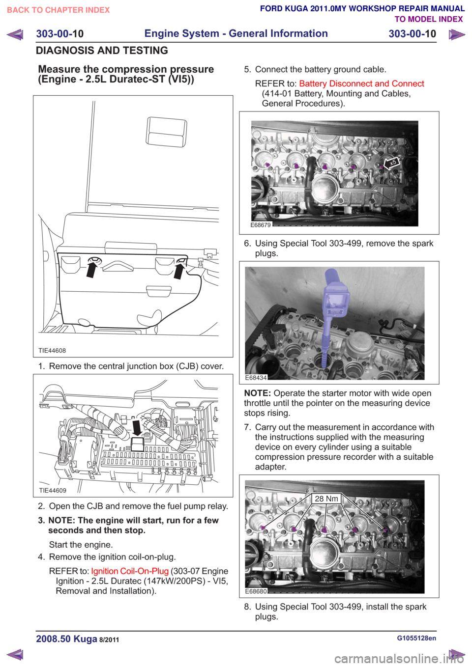
Measure the compression pressure
(Engine - 2.5L Duratec-ST (VI5))
TIE44608
1. Remove the central junction box (CJB) cover.
TIE44609
2. Open the CJB and remove the fuel pump relay.
3. NOTE: The engine will start, run for a fewseconds and then stop.
Start the engine.
4. Remove the ignition coil-on-plug.
REFER to: Ignition Coil-On-Plug (303-07 Engine
Ignition - 2.5L Duratec (147kW/200PS) - VI5,
Removal and Installation). 5. Connect the battery ground cable.
REFER to: Battery Disconnect and Connect
(414-01 Battery, Mounting and Cables,
General Procedures).
E68679
x5
6. Using Special Tool 303-499, remove the spark plugs.
E68434
NOTE: Operate the starter motor with wide open
throttle until the pointer on the measuring device
stops rising.
7. Carry out the measurement in accordance with the instructions supplied with the measuring
device on every cylinder using a suitable
compression pressure recorder with a suitable
adapter.
E68680
28 Nm
8. Using Special Tool 303-499, install the sparkplugs.
G1055128en2008.50 Kuga8/2011
303-00- 10
Engine System - General Information
303-00- 10
DIAGNOSIS AND TESTING
TO MODEL INDEX
BACK TO CHAPTER INDEX
FORD KUGA 2011.0MY WORKSHOP REPAIR MANUAL
Page 1529 of 2057
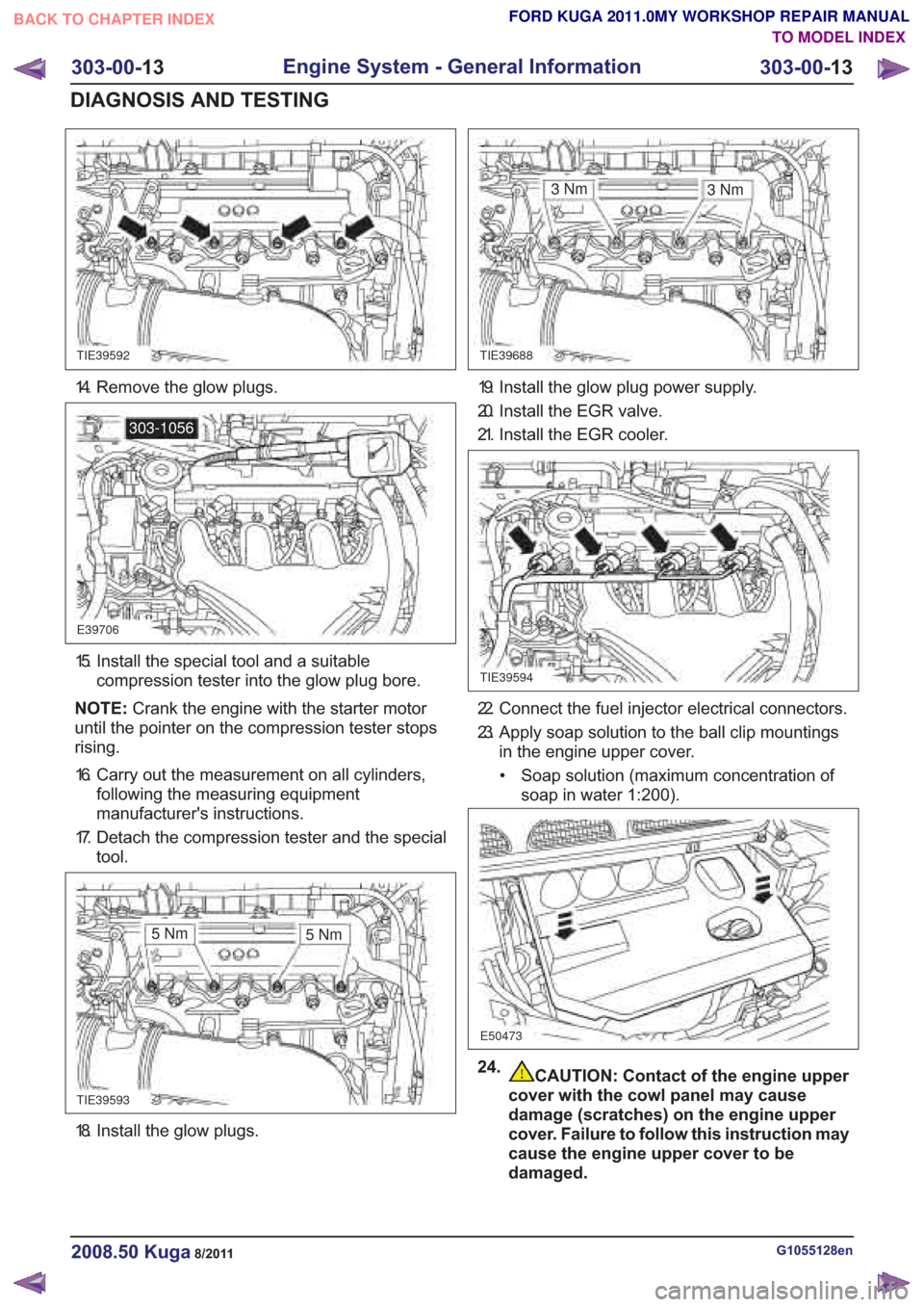
18. Install the glow plugs.
CAUTION: Contact of the engine upper
cover with the cowl panel may cause
damage (scratches) on the engine upper
cover. Failure to follow this instruction may
cause the engine upper cover to be
damaged.
G1055128en2008.50 Kuga8/2011
303-00- 13
Engine System - General Information
303-00- 13
DIAGNOSIS AND TESTING
FORD KUGA 2011.0MY WORKSHOP REPAIR MANUAL
TO MODEL INDEX
BACK TO CHAPTER INDEX
TIE39592TIE39688
E39706
303-1056
TIE39593
3Nm
TIE39594
E50473
3Nm
5Nm 5Nm
14. Remove the glow plugs.
15. Install the special tool and a suitable
compression tester into the glow plug bore.
NOTE: Crank the engine with the starter motor
until the pointer on the compression tester stops
rising.
16. Carry out the measurement on all cylinders, following the measuring equipment
manufacturer's instructions.
17. Detach the compression tester and the special tool.
19. Install the glow plug power supply.
20. Install the EGR valve.
21. Install the EGR cooler.
22. Connect the fuel injector electrical connectors.
23. Apply soap solution to the ball clip mountingsin the engine upper cover.
• Soap solution (maximum concentration of soap in water 1:200).
24.
Page 1530 of 2057
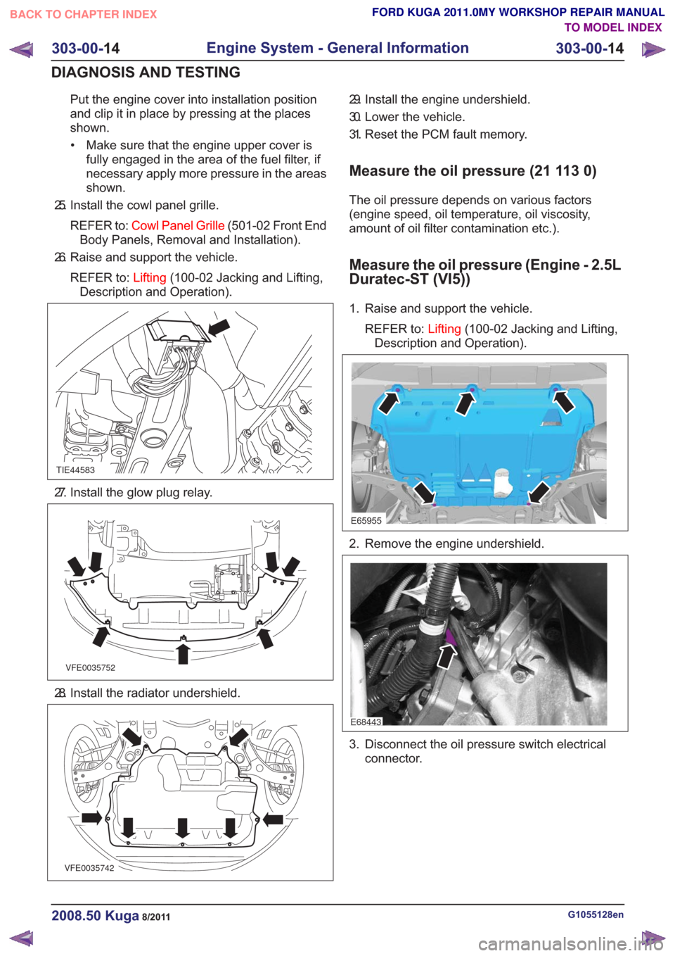
Put the engine cover into installation position
and clip it in place by pressing at the places
shown.• Make sure that the engine upper cover is fully engaged in the area of the fuel filter, if
necessary apply more pressure in the areas
shown.
25. Install the cowl panel grille.
REFER to: Cowl Panel Grille (501-02 Front End
Body Panels, Removal and Installation).
26. Raise and support the vehicle.
REFER to: Lifting(100-02 Jacking and Lifting,
Description and Operation).
TIE44583
27. Install the glow plug relay.
VFE0035752
28. Install the radiator undershield.
VFE0035742
29. Install the engine undershield.
30. Lower the vehicle.
31. Reset the PCM fault memory.
Measure the oil pressure (21 113 0)
The oil pressure depends on various factors
(engine speed, oil temperature, oil viscosity,
amount of oil filter contamination etc.).
Measure the oil pressure (Engine - 2.5L
Duratec-ST (VI5))
1. Raise and support the vehicle.
REFER to: Lifting(100-02 Jacking and Lifting,
Description and Operation).
E65955
2. Remove the engine undershield.
E68443
3. Disconnect the oil pressure switch electrical connector.
G1055128en2008.50 Kuga8/2011
303-00- 14
Engine System - General Information
303-00- 14
DIAGNOSIS AND TESTING
TO MODEL INDEX
BACK TO CHAPTER INDEX
FORD KUGA 2011.0MY WORKSHOP REPAIR MANUAL
Page 1553 of 2057
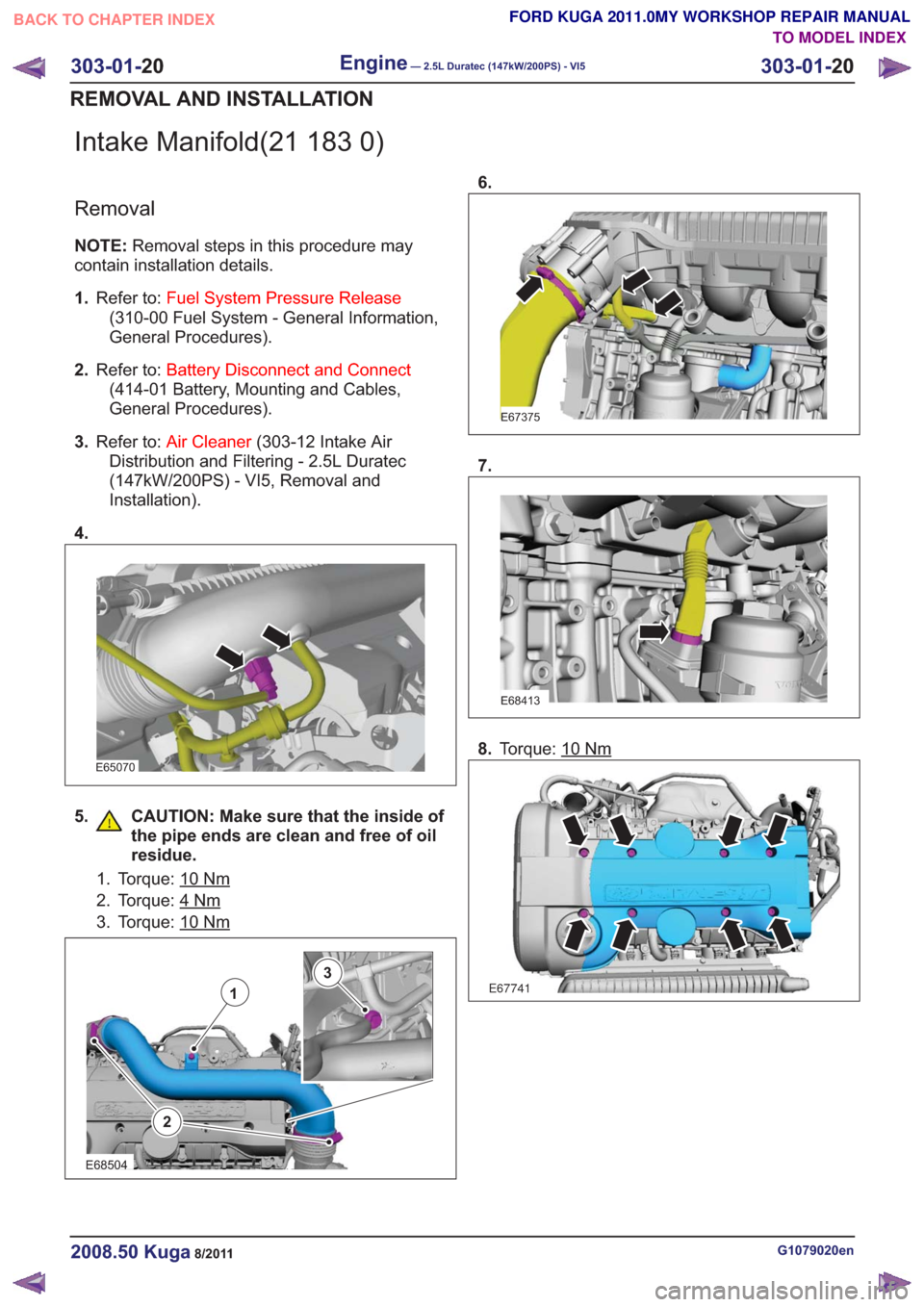
Intake Manifold(21 183 0)
Removal
NOTE:Removal steps in this procedure may
contain installation details.
1. Refer to: Fuel System Pressure Release
(310-00 Fuel System - General Information,
General Procedures).
2. Refer to: Battery Disconnect and Connect
(414-01 Battery, Mounting and Cables,
General Procedures).
3. Refer to: Air Cleaner (303-12 Intake Air
Distribution and Filtering - 2.5L Duratec
(147kW/200PS) - VI5, Removal and
Installation).
4.
E65070
5. CAUTION: Make sure that the inside of the pipe ends are clean and free of oil
residue.
1. Torque: 10Nm
2. Torque: 4Nm
3. Torque: 10Nm
2
1
3
E68504
6.
E67375
7.
E68413
8.Torque: 10Nm
E67741
G1079020en2008.50 Kuga8/2011
303-01- 20
Engine— 2.5L Duratec (147kW/200PS) - VI5303-01-
20
REMOVAL AND INSTALLATION
TO MODEL INDEX
BACK TO CHAPTER INDEX
FORD KUGA 2011.0MY WORKSHOP REPAIR MANUAL
Page 1583 of 2057
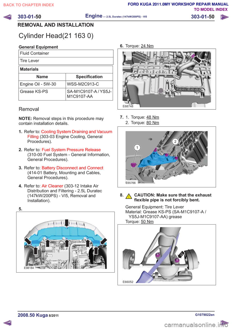
Cylinder Head(21 163 0)
General EquipmentFluid Container
Tire Lever
Materials
Specification
Name
WSS-M2C913-C
Engine Oil - 5W-30
SA-M1C9107-A / YS5J-
M1C9107-AA
Grease KS-PS
Removal
NOTE:
Removal steps in this procedure may
contain installation details.
1. Refer to: Cooling System Draining and Vacuum
Filling (303-03 Engine Cooling, General
Procedures).
2. Refer to: Fuel System Pressure Release
(310-00 Fuel System - General Information,
General Procedures).
3. Refer to: Battery Disconnect and Connect
(414-01 Battery, Mounting and Cables,
General Procedures).
4. Refer to: Air Cleaner (303-12 Intake Air
Distribution and Filtering - 2.5L Duratec
(147kW/200PS) - VI5, Removal and
Installation).
5.
E98184
6. Torque: 24Nm
E68748
7. Torque: 48Nm1.
2. Torque: 80
Nm
E65766
1
2
8. CAUTION: Make sure that the exhaust
flexible pipe is not forcibly bent.
General Equipment: Tire Lever
Material: Grease KS-PS (SA-M1C9107-A /YS5J-M1C9107-AA) grease
Torque: 50
Nm
E66052
x2
G1079022en2008.50 Kuga8/2011
303-01- 50
Engine— 2.5L Duratec (147kW/200PS) - VI5303-01-
50
REMOVAL AND INSTALLATION
TO MODEL INDEX
BACK TO CHAPTER INDEX
FORD KUGA 2011.0MY WORKSHOP REPAIR MANUAL