Page 170 of 2057
Auxiliary Coolant Flow Pump
General Equipment
Hose Clamp(s) General Equipment
Hose Clamp Remover/Installer
Removal
1. Refer to: Engine Cooling System Health and
Safety Precautions (100-00 General
Information, Description and Operation).
2. Refer to: Jacking(100-02 Jacking and Lifting,
Description and Operation).
3. General Equipment: Hose Clamp(s)
General Equipment: Hose Clamp
Remover/Installer Installation
1.
To install, reverse the removal procedure.
2. Check the coolant level.
Refer to: Cooling System Draining and Vacuum
Filling (303-03 Engine Cooling, General
Procedures). G1163562en
2008.50 Kuga 8/2011 412-02-17
Auxiliary Climate Control
412-02-17
REMOVAL AND INSTALLATIONTO MODEL INDEX
BACK TO CHAPTER INDEX
FORD KUGA 2011.0MY WORKSHOP REPAIR MANUAL11E112651
Page 177 of 2057
7.
Installation
1.
To install, reverse the removal procedure.
2. Check the coolant level.
Refer to: Cooling System Draining and Vacuum
Filling (303-03 Engine Cooling, General
Procedures). G1163563en
2008.50 Kuga 8/2011 412-02-24
Auxiliary Climate Control
412-02-24
REMOVAL AND INSTALLATIONTO MODEL INDEX
BACK TO CHAPTER INDEX
FORD KUGA 2011.0MY WORKSHOP REPAIR MANUALE112645
Page 199 of 2057

Oil Change Indicator Reset
1.
Turn the ignition key to position II without
cranking the engine.
2. Simultaneously press and hold the accelerator
pedal and the brake pedal for approximately 15
seconds until the oil change reminder indicator
starts to flash or the "Service Oil Reset
Complete" message appears in the information
and message center (if equipped).
3. Release the pedals.
4. Check that the oil change reminder indicator
has turned off or that there is no "Service Oil"
message in the information and message center
(if equipped). If the oil change reminder indicator
is still illuminated or the "Service Oil" message
is still displayed, turn the ignition key to position
0 and repeat the procedure from Step 1. If it has
turned off or the "Service Oil" message has
disappeared, proceed to Step 5.
5. Turn the ignition key to position 0 and leave it
there for at least 2 minutes so that the
powertrain control module (PCM) fully powers
down and updates the non-volatile memory
(NVM) in the PCM.
6. Turn the ignition key to position II without
cranking the engine and check that the oil
change reminder indicator is not illuminated or
that there is no "Service Oil" message displayed.
7. Turn the ignition key to position 0. G898940en
2008.50 Kuga 8/2011 413-09-4
Warning Devices
413-09-4
GENERAL PROCEDURESTO MODEL INDEX
BACK TO CHAPTER INDEX
FORD KUGA 2011.0MY WORKSHOP REPAIR MANUAL
Page 263 of 2057

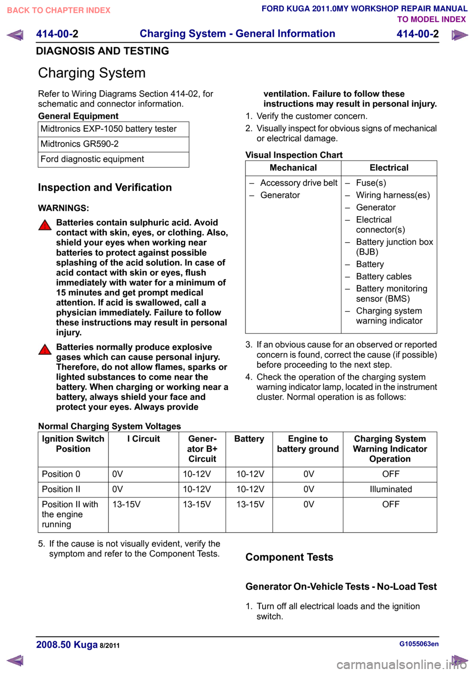
Charging System
Refer to Wiring Diagrams Section 414-02, for
schematic and connector information.
General Equipment
Midtronics EXP-1050 battery tester
Midtronics GR590-2
Ford diagnostic equipment
Inspection and Verification
WARNINGS: Batteries contain sulphuric acid. Avoid
contact with skin, eyes, or clothing. Also,
shield your eyes when working near
batteries to protect against possible
splashing of the acid solution. In case of
acid contact with skin or eyes, flush
immediately with water for a minimum of
15 minutes and get prompt medical
attention. If acid is swallowed, call a
physician immediately. Failure to follow
these instructions may result in personal
injury.
Batteries normally produce explosive
gases which can cause personal injury.
Therefore, do not allow flames, sparks or
lighted substances to come near the
battery. When charging or working near a
battery, always shield your face and
protect your eyes. Always provide
ventilation. Failure to follow these
instructions may result in personal injury.
1. Verify the customer concern.
2. Visually inspect for obvious signs of mechanical
or electrical damage.
Visual Inspection Chart Electrical
Mechanical
– Fuse(s)
– Wiring harness(es)
– Generator
– Electricalconnector(s)
– Battery junction box (BJB)
– Battery
– Battery cables
– Battery monitoring sensor (BMS)
– Charging system warning indicator
–
Accessory drive belt
– Generator
3. If an obvious cause for an observed or reported concern is found, correct the cause (if possible)
before proceeding to the next step.
4. Check the operation of the charging system warning indicator lamp, located in the instrument
cluster. Normal operation is as follows:
Normal Charging System Voltages Charging System
Warning Indicator Operation
Engine to
battery ground
Battery
Gener-
ator B+ Circuit
I Circuit
Ignition Switch
Position
OFF
0V
10-12V
10-12V
0V
Position 0
Illuminated
0V
10-12V
10-12V
0V
Position II
OFF
0V
13-15V
13-15V
13-15V
Position II with
the engine
running
5. If the cause is not visually evident, verify the symptom and refer to the Component Tests. Component Tests
Generator On-Vehicle Tests - No-Load Test
1. Turn off all electrical loads and the ignition
switch. G1055063en
2008.50 Kuga 8/2011 414-00-2
Charging System - General Information
414-00-2
DIAGNOSIS AND TESTINGTO MODEL INDEX
BACK TO CHAPTER INDEX
FORD KUGA 2011.0MY WORKSHOP REPAIR MANUAL
Page 1233 of 2057

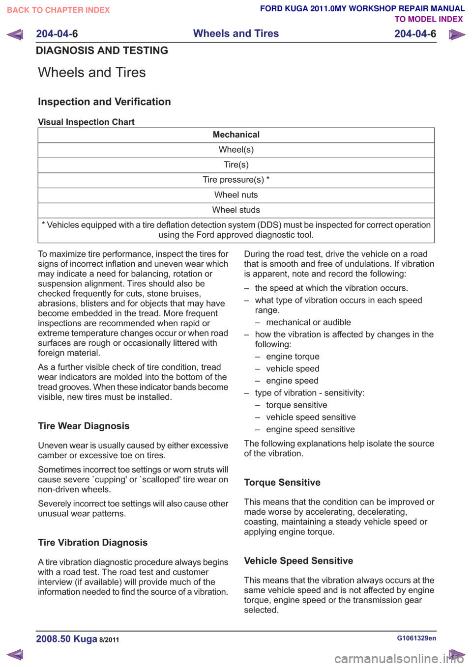
Wheels and Tires
Inspection and Verification
Visual Inspection Chart
MechanicalWheel(s)Tire(s)
Tire pressure(s) * Wheel nuts
Wheel studs
* Vehicles equipped with a tire deflation detection system (DDS) must be inspected for correct operation using the Ford approved diagnostic tool.
To maximize tire performance, inspect the tires for
signs of incorrect inflation and uneven wear which
may indicate a need for balancing, rotation or
suspension alignment. Tires should also be
checked frequently for cuts, stone bruises,
abrasions, blisters and for objects that may have
become embedded in the tread. More frequent
inspections are recommended when rapid or
extreme temperature changes occur or when road
surfaces are rough or occasionally littered with
foreign material.
As a further visible check of tire condition, tread
wear indicators are molded into the bottom of the
tread grooves. When these indicator bands become
visible, new tires must be installed.
Tire Wear Diagnosis
Uneven wear is usually caused by either excessive
camber or excessive toe on tires.
Sometimes incorrect toe settings or worn struts will
cause severe `cupping' or `scalloped' tire wear on
non-driven wheels.
Severely incorrect toe settings will also cause other
unusual wear patterns.
Tire Vibration Diagnosis
A tire vibration diagnostic procedure always begins
with a road test. The road test and customer
interview (if available) will provide much of the
information needed to find the source of a vibration. During the road test, drive the vehicle on a road
that is smooth and free of undulations. If vibration
is apparent, note and record the following:
– the speed at which the vibration occurs.
– what type of vibration occurs in each speed
range.
– mechanical or audible
– how the vibration is affected by changes in the following:
– engine torque
– vehicle speed
– engine speed
– type of vibration - sensitivity: – torque sensitive
– vehicle speed sensitive
– engine speed sensitive
The following explanations help isolate the source
of the vibration.
Torque Sensitive
This means that the condition can be improved or
made worse by accelerating, decelerating,
coasting, maintaining a steady vehicle speed or
applying engine torque.
Vehicle Speed Sensitive
This means that the vibration always occurs at the
same vehicle speed and is not affected by engine
torque, engine speed or the transmission gear
selected.
G1061329en2008.50 Kuga8/2011
204-04- 6
Wheels and Tires
204-04- 6
DIAGNOSIS AND TESTING
TO MODEL INDEX
BACK TO CHAPTER INDEX
FORD KUGA 2011.0MY WORKSHOP REPAIR MANUAL
Page 1269 of 2057
Vehicles with 2.5L engine
6.
x2x2
E114255
7.Torque: 80Nm
E114256
8.Refer to: Driveshaft (205-01 Driveshaft,
Removal and Installation).
All vehicles
9. Refer to: Rear Halfshaft (205-05 Rear Drive
Halfshafts, Removal and Installation).
10. Refer to: Differential Fluid Level Check (205-02
Rear Drive Axle/Differential, General
Procedures).
G1061458en2008.50 Kuga8/2011
205-02- 24
Rear Drive Axle/Differential
205-02- 24
REMOVAL AND INSTALLATION
TO MODEL INDEX
BACK TO CHAPTER INDEX
FORD KUGA 2011.0MY WORKSHOP REPAIR MANUAL
Page 1299 of 2057

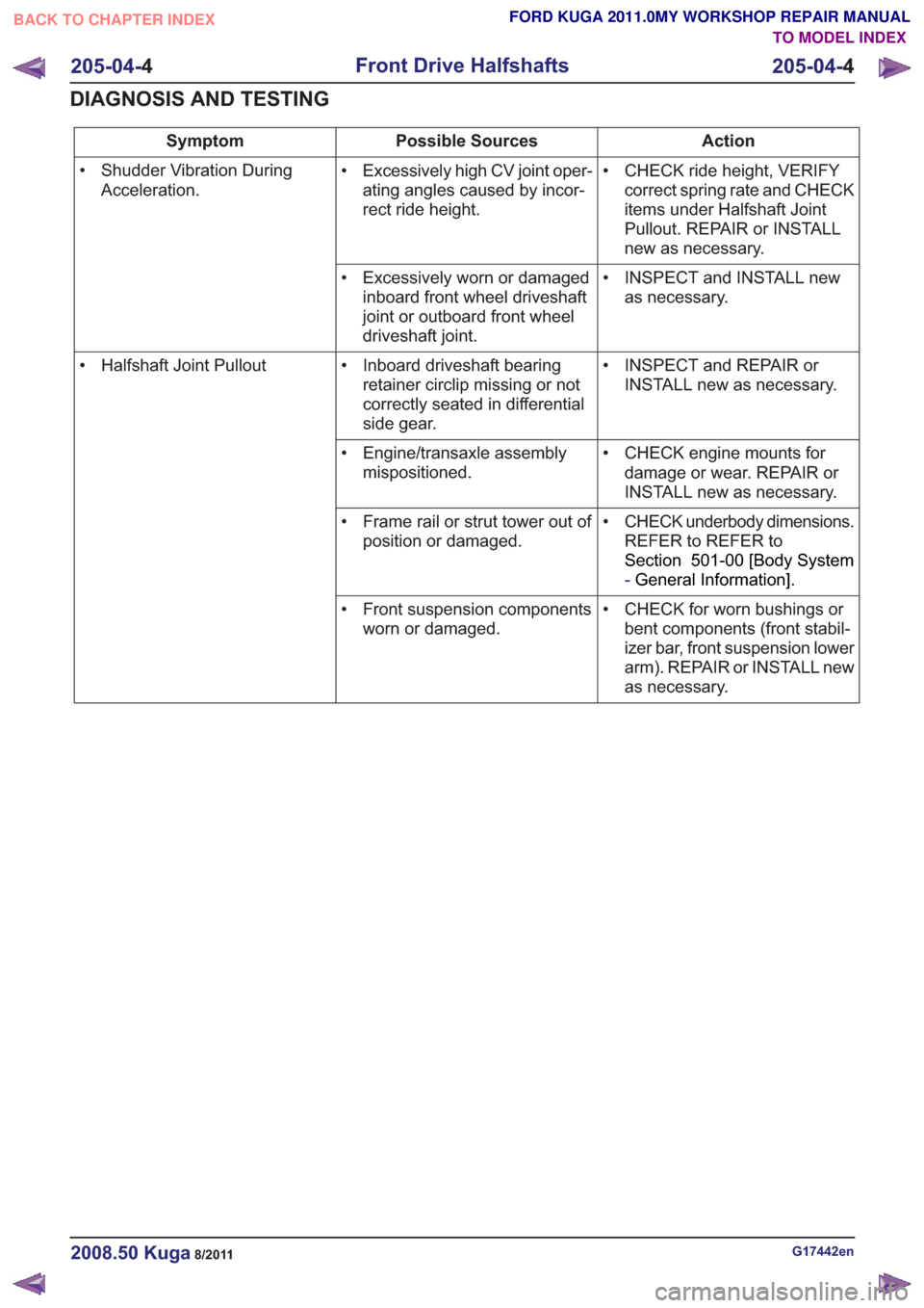
Action
Possible Sources
Symptom
• CHECK ride height, VERIFYcorrect spring rate and CHECK
items under Halfshaft Joint
Pullout. REPAIR or INSTALL
new as necessary.
• Excessively high CV joint oper-
ating angles caused by incor-
rect ride height.
• Shudder Vibration During
Acceleration.
• INSPECT and INSTALL newas necessary.
• Excessively worn or damaged
inboard front wheel driveshaft
joint or outboard front wheel
driveshaft joint.
• INSPECT and REPAIR orINSTALL new as necessary.
• Inboard driveshaft bearing
retainer circlip missing or not
correctly seated in differential
side gear.
• Halfshaft Joint Pullout
• CHECK engine mounts fordamage or wear. REPAIR or
INSTALL new as necessary.
• Engine/transaxle assembly
mispositioned.
• CHECK underbody dimensions.REFER to REFER to
Section 501-00 [Body System
-General Information] .
• Frame rail or strut tower out of
position or damaged.
• CHECK for worn bushings orbent components (front stabil-
izer bar, front suspension lower
arm). REPAIR or INSTALL new
as necessary.
• Front suspension components
worn or damaged.
G17442en2008.50 Kuga8/2011
205-04- 4
Front Drive Halfshafts
205-04- 4
DIAGNOSIS AND TESTING
TO MODEL INDEX
BACK TO CHAPTER INDEX
FORD KUGA 2011.0MY WORKSHOP REPAIR MANUAL
Page 1344 of 2057

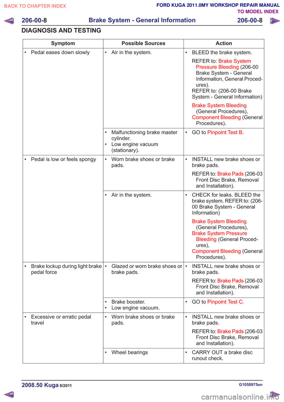
Action
Possible Sources
Symptom
• BLEED the brake system.REFER to: Brake System
Pressure Bleeding (206-00
Brake System - General
Information, General Proced-
ures).
REFER to: (206-00 Brake
System - General Information)
Brake System Bleeding (General Procedures),
Component Bleeding (General
Procedures).
• Air in the system.
• Pedal eases down slowly
• GO toPinpoint Test B.
• Malfunctioning brake master
cylinder.
• Low engine vacuum (stationary).
• INSTALL new brake shoes orbrake pads.
REFER to: Brake Pads (206-03
Front Disc Brake, Removal
and Installation).
• Worn brake shoes or brake
pads.
• Pedal is low or feels spongy
• CHECK for leaks. BLEED thebrake system. REFER to: (206-
00 Brake System - General
Information)
Brake System Bleeding (General Procedures),
Brake System Pressure Bleeding (General Proced-
ures),
Component Bleeding (General
Procedures).
• Air in the system.
• INSTALL new brake shoes orbrake pads.
REFER to: Brake Pads (206-03
Front Disc Brake, Removal
and Installation).
• Glazed or worn brake shoes or
brake pads.
• Brake lockup during light brake
pedal force
• GO toPinpoint Test C.
• Brake booster.
• Low engine vacuum.
• INSTALL new brake shoes orbrake pads.
REFER to: Brake Pads (206-03
Front Disc Brake, Removal
and Installation).
• Worn brake shoes or brake
pads.
• Excessive or erratic pedal
travel
• CARRY OUT a brake discrunout check.
• Wheel bearings
G1058975en2008.50 Kuga8/2011
206-00-
8
Brake System - General Information
206-00- 8
DIAGNOSIS AND TESTING
TO MODEL INDEX
BACK TO CHAPTER INDEX
FORD KUGA 2011.0MY WORKSHOP REPAIR MANUAL