Page 1720 of 2057

Turbocharger – Overview
Turbocharger(s)
CAUTION: Do not switch off the engine
while it is running at high speed. If the
engine is switched off while it is running
at high speed, the turbocharger will
continue to run after the engine oil
pressure has already dropped to zero. This
will cause premature wear in the
turbocharger bearings.
A TC consists of an exhaust turbine located in the
exhaust gas flow, this turbine is connected to a
compressor by a shaft. The turbine is made to
rotate by the exhaust gas flow from the engine and
thus drives the compressor. The compressor
increases the pressure in the engine intake tract
so that a greater mass of air enters the cylinder
during the intake stroke.
The turbine housing of the TC is integrated into the
exhaust manifold. This construction offers
thermodynamic advantages compared with the
usual construction, the maximum exhaust
temperature is up to 1050°C.
The maximum boost pressure is 0.65 bar.
The exhaust manifold is secured to the exhaust
side of the cylinder head with 12 self-locking nuts.
The exhaust manifold gasket is a multi-layer steel
gasket and cannot be reused. In order to
compensate for the thermal expansion of the
exhaust manifold, the flange of the TC is provided
with two grooves.
The TC and the exhaust manifold are joined by a
hose clip. The hose clip must not be loosened or
removed. The TC and the exhaust manifold are
not available as separate replacement parts,
exchange is only possible as a complete unit.
The turbocharger heat shield is secured to the
exhaust manifold by four bolts. Two of the bolts
have spring washers underneath their heads.
During removal, make a note of the installation
location of the spring washers to refer to during
installation.
The recirculated air valve is built into the TC
housing and cannot be changed.
The Ford diagnostic unit can test the operation of
the wastegate control valve using actuator
diagnosis.
The boost pressure regulator is set in the factory.
Adjustments to the boost pressure regulator must never be attempted. A red colored seal is applied
to the adjustment nut of the operating rod, in order
to monitor the factory setting of the boost pressure.
The bearings of the TC are lubricated with engine
oil. The engine oil passes from the cylinder block
through the oil supply pipe to the TC. The oil is
returned to the oil pan through the oil return pipe,
The TC is cooled by the engine coolant circuit.
When installing hoses and lines, make certain that
their ends are free of oil residues and dirt.
G1032425en2008.50 Kuga8/2011
303-04B-
4
Fuel Charging and Controls - Turbocharger
—
2.5L Duratec (147kW/200PS) - VI5
303-04B- 4
DESCRIPTION AND OPERATION
TO MODEL INDEX
BACK TO CHAPTER INDEX
FORD KUGA 2011.0MY WORKSHOP REPAIR MANUAL
Page 1783 of 2057

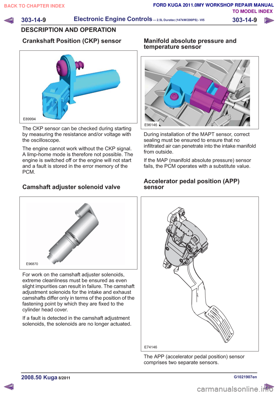
Crankshaft Position (CKP) sensor
E89994
The CKP sensor can be checked during starting
by measuring the resistance and/or voltage with
the oscilloscope.
The engine cannot work without the CKP signal.
A limp-home mode is therefore not possible. The
engine is switched off or the engine will not start
and a fault is stored in the error memory of the
PCM.
Camshaft adjuster solenoid valve
E96870
For work on the camshaft adjuster solenoids,
extreme cleanliness must be ensured as even
slight impurities can result in failure. The camshaft
adjustment solenoids for the intake and exhaust
camshafts differ only in terms of the position of the
fastening point by which they are fixed to the
cylinder head cover.
If a fault is detected in the camshaft adjustment
solenoids, the solenoids are no longer actuated.
Manifold absolute pressure and
temperature sensor
E96146
During installation of the MAPT sensor, correct
sealing must be ensured to ensure that no
infiltrated air can penetrate into the intake manifold
from outside.
If the MAP (manifold absolute pressure) sensor
fails, the PCM operates with a substitute value.
Accelerator pedal position (APP)
sensor
E74146
The APP (accelerator pedal position) sensor
comprises two separate sensors.
G1021907en2008.50 Kuga8/2011
303-14-9
Electronic Engine Controls— 2.5L Duratec (147kW/200PS) - VI5303-14-
9
DESCRIPTION AND OPERATION
TO MODEL INDEX
BACK TO CHAPTER INDEX
FORD KUGA 2011.0MY WORKSHOP REPAIR MANUAL
Page 1794 of 2057

than to a change in the throttle valve position. The
ignition timing also changes much more quickly.
To keep the ignition point as close as possible to
the knock limit and so optimize the efficiency of the
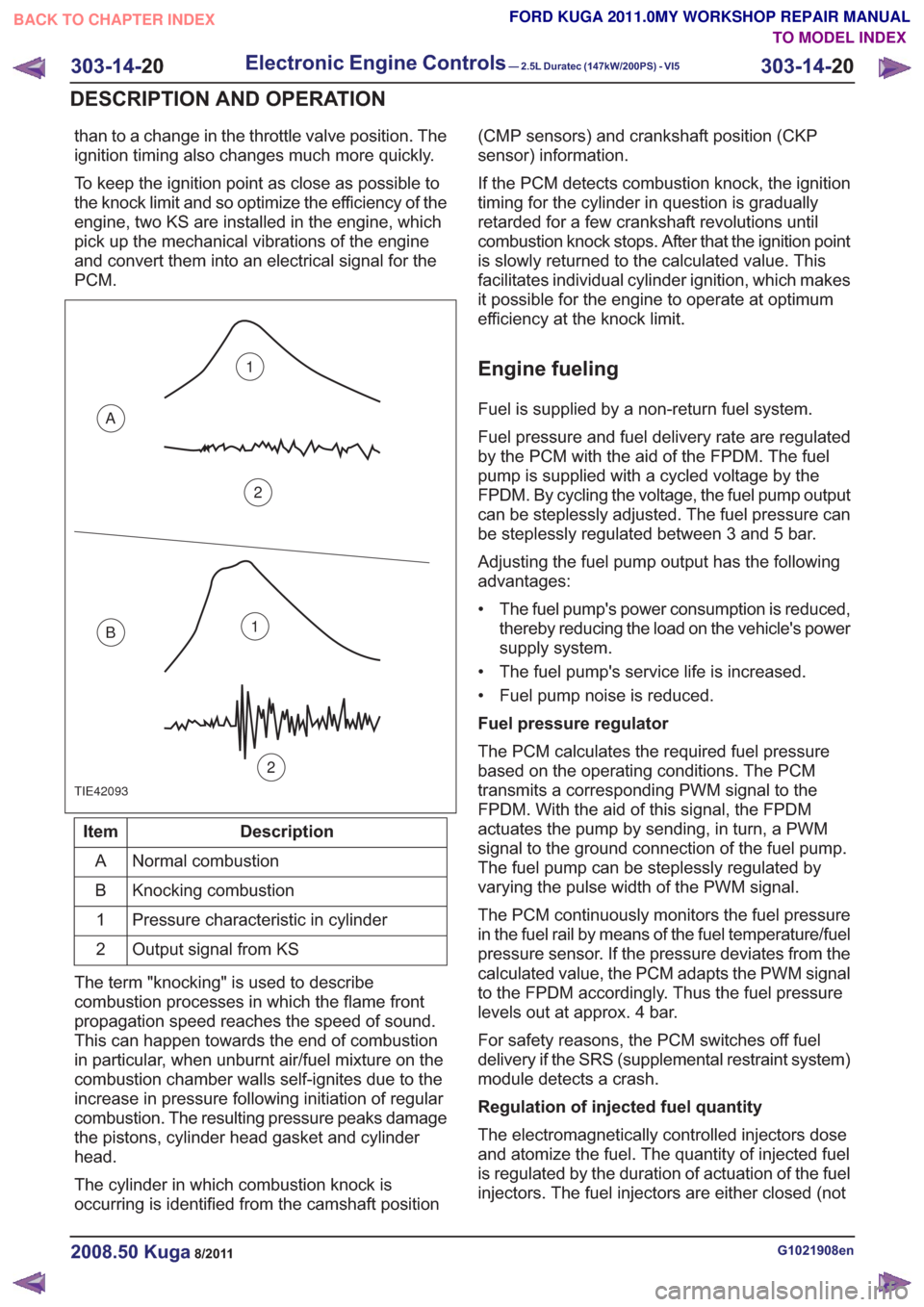
engine, two KS are installed in the engine, which
pick up the mechanical vibrations of the engine
and convert them into an electrical signal for the
PCM.
TIE42093
1
2
A
B1
2
Description
Item
Normal combustion
A
Knocking combustion
B
Pressure characteristic in cylinder
1
Output signal from KS
2
The term "knocking" is used to describe
combustion processes in which the flame front
propagation speed reaches the speed of sound.
This can happen towards the end of combustion
in particular, when unburnt air/fuel mixture on the
combustion chamber walls self-ignites due to the
increase in pressure following initiation of regular
combustion. The resulting pressure peaks damage
the pistons, cylinder head gasket and cylinder
head.
The cylinder in which combustion knock is
occurring is identified from the camshaft position (CMP sensors) and crankshaft position (CKP
sensor) information.
If the PCM detects combustion knock, the ignition
timing for the cylinder in question is gradually
retarded for a few crankshaft revolutions until
combustion knock stops. After that the ignition point
is slowly returned to the calculated value. This
facilitates individual cylinder ignition, which makes
it possible for the engine to operate at optimum
efficiency at the knock limit.
Engine fueling
Fuel is supplied by a non-return fuel system.
Fuel pressure and fuel delivery rate are regulated
by the PCM with the aid of the FPDM. The fuel
pump is supplied with a cycled voltage by the
FPDM. By cycling the voltage, the fuel pump output
can be steplessly adjusted. The fuel pressure can
be steplessly regulated between 3 and 5 bar.
Adjusting the fuel pump output has the following
advantages:
• The fuel pump's power consumption is reduced,
thereby reducing the load on the vehicle's power
supply system.
• The fuel pump's service life is increased.
• Fuel pump noise is reduced.
Fuel pressure regulator
The PCM calculates the required fuel pressure
based on the operating conditions. The PCM
transmits a corresponding PWM signal to the
FPDM. With the aid of this signal, the FPDM
actuates the pump by sending, in turn, a PWM
signal to the ground connection of the fuel pump.
The fuel pump can be steplessly regulated by
varying the pulse width of the PWM signal.
The PCM continuously monitors the fuel pressure
in the fuel rail by means of the fuel temperature/fuel
pressure sensor. If the pressure deviates from the
calculated value, the PCM adapts the PWM signal
to the FPDM accordingly. Thus the fuel pressure
levels out at approx. 4 bar.
For safety reasons, the PCM switches off fuel
delivery if the SRS (supplemental restraint system)
module detects a crash.
Regulation of injected fuel quantity
The electromagnetically controlled injectors dose
and atomize the fuel. The quantity of injected fuel
is regulated by the duration of actuation of the fuel
injectors. The fuel injectors are either closed (not
G1021908en2008.50 Kuga8/2011
303-14- 20
Electronic Engine Controls— 2.5L Duratec (147kW/200PS) - VI5303-14-
20
DESCRIPTION AND OPERATION
TO MODEL INDEX
BACK TO CHAPTER INDEX
FORD KUGA 2011.0MY WORKSHOP REPAIR MANUAL
Page:
< prev 1-8 9-16 17-24