Page 2037 of 2057

Climate Control – Overview
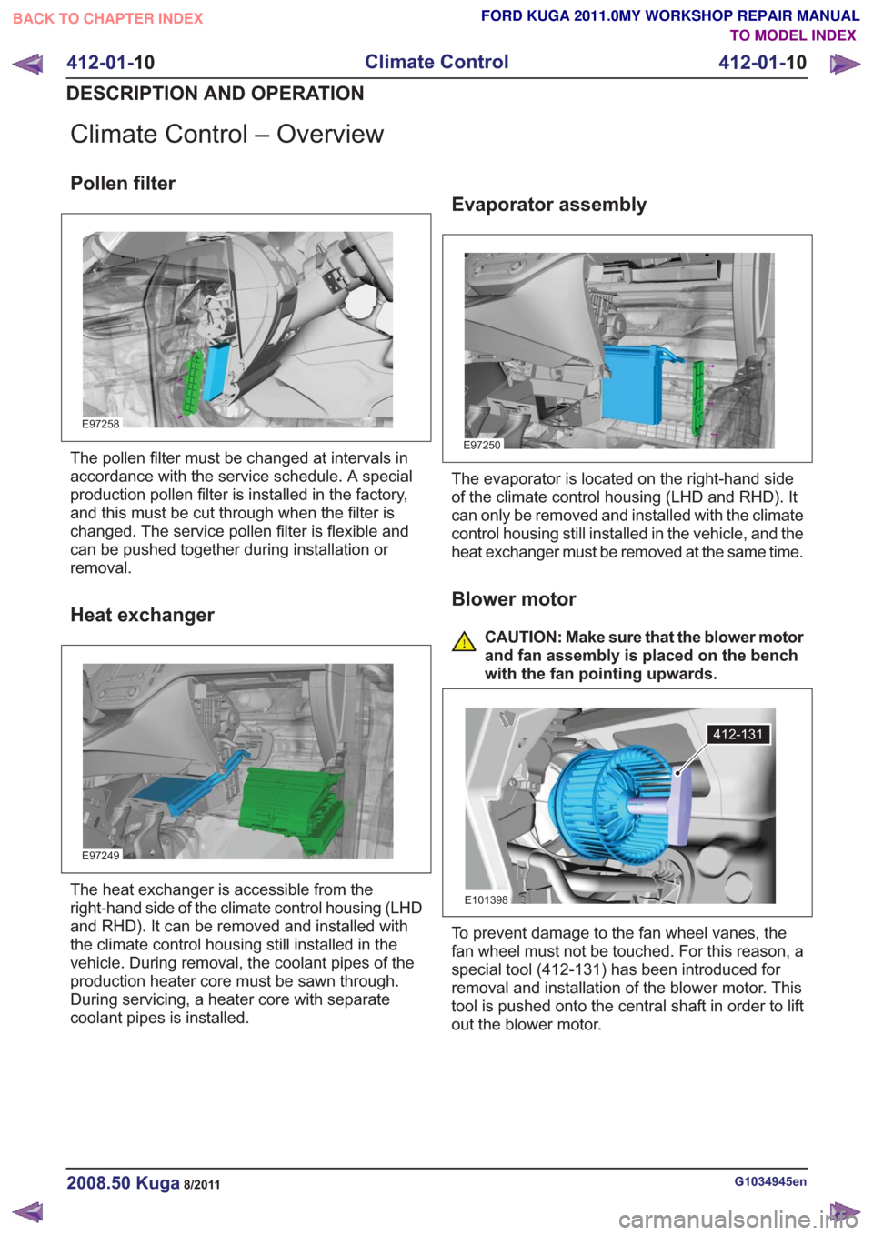
Pollen filter
E97258
The pollen filter must be changed at intervals in
accordance with the service schedule. A special
production pollen filter is installed in the factory,
and this must be cut through when the filter is
changed. The service pollen filter is flexible and
can be pushed together during installation or
removal.
Heat exchanger
E97249
The heat exchanger is accessible from the
right-hand side of the climate control housing (LHD
and RHD). It can be removed and installed with
the climate control housing still installed in the
vehicle. During removal, the coolant pipes of the
production heater core must be sawn through.
During servicing, a heater core with separate
coolant pipes is installed.
Evaporator assembly
E97250
The evaporator is located on the right-hand side
of the climate control housing (LHD and RHD). It
can only be removed and installed with the climate
control housing still installed in the vehicle, and the
heat exchanger must be removed at the same time.
Blower motor
CAUTION: Make sure that the blower motor
and fan assembly is placed on the bench
with the fan pointing upwards.
412-131
E101398
To prevent damage to the fan wheel vanes, the
fan wheel must not be touched. For this reason, a
special tool (412-131) has been introduced for
removal and installation of the blower motor. This
tool is pushed onto the central shaft in order to lift
out the blower motor.
G1034945en2008.50 Kuga8/2011
412-01-10
Climate Control
412-01- 10
DESCRIPTION AND OPERATION
TO MODEL INDEX
BACK TO CHAPTER INDEX
FORD KUGA 2011.0MY WORKSHOP REPAIR MANUAL
Page 2038 of 2057

Fault Memory Interrogation without
diagnostics unit - vehicles with
automatic temperature control
NOTE:On vehicles equipped with a DVD
navigation system with touchscreen, the fault
memory can only be interrogated using the Ford
diagnostic tool.
The climate control and heating system features
a on-board diagnosis function which can detect
and store both current permanent faults as well as
intermittent faults which have occurred during
normal operation of the vehicle. It is also possible
to read out these faults via the display on the
control panel of the climate control system. To read
out the fault memory, the ignition key must be
turned to the "ON" position and the battery voltage
must be between 9 V and 16 V.
To activate the on-board diagnosis at the control
panel for the climate control system, PRESS the
"OFF" and "FOOTWELL" buttons simultaneously
for exactly 2 seconds, then PRESS "AUTO" within
1.5 seconds. The on-board diagnosis which then
starts lasts a few seconds. An animated display
appears in the display of the control panel for the
climate control system during this time. Any faults
found are displayed on both displays of the control
panel for the climate control system in the form of
trouble codes.
To read out saved errors at the control panel for
the climate control system, PRESS the "OFF" and
"FOOTWELL" buttons simultaneously for exactly
2 seconds, then PRESS "HEAD AREA" within 1.5
seconds. Any stored faults are shown on the
display of the control panel for the climate control
system and should be noted for safety reasons.
By PRESSING the "DEFROST" button, the fault
memory is cleared and diagnosis mode is ended.
To end the diagnostic mode without clearing the
DTCs, PRESS any other operating button on the
control panel for the climate control system.
To read out the software version at the control
panel for the climate control system, PRESS the
"OFF" and "FOOTWELL" buttons simultaneously
for exactly 2 seconds, then PRESS "A/C" within
1.5 seconds. The software version is shown on the
display of the control panel for the climate control
system. The output mode can be exited by
PRESSING any button on the control panel for the
climate control system.
Switch over from Celsius to Fahrenheit
The switch from Celsius to Fahrenheit is performed
on the display of the instrument cluster and is then
transmitted via the CAN bus to the module of the
two-zone air conditioning system.
G1034945en2008.50 Kuga8/2011
412-01- 11
Climate Control
412-01- 11
DESCRIPTION AND OPERATION
TO MODEL INDEX
BACK TO CHAPTER INDEX
FORD KUGA 2011.0MY WORKSHOP REPAIR MANUAL
Page 2039 of 2057
Climate Control – System Operation and Component Description
System Diagram
Climate control system - vehicles with manual temperature control
3214
E97574
Description
Item
Climate control system control assemblyRefer to Component Description: Control
assembly, climate control - vehicles with
manualtemperaturecontrol(page24)
1
Air flap actuator
2Description
Item
Blower motor resistor
3
Blower motor
4
G1034947en2008.50 Kuga8/2011
412-01- 12
Climate Control
412-01- 12
DESCRIPTION AND OPERATION
TO MODEL INDEX
BACK TO CHAPTER INDEX
FORD KUGA 2011.0MY WORKSHOP REPAIR MANUAL
Page 2040 of 2057
Climate control system - vehicles with automatic temperature control
16
15
4
1
2
5
12
13
14
6
9
3
8
7
11
10
E97575
MS-CAN
G1034947en2008.50 Kuga8/2011
412-01-13
Climate Control
412-01- 13
DESCRIPTION AND OPERATION
TO MODEL INDEX
BACK TO CHAPTER INDEX
FORD KUGA 2011.0MY WORKSHOP REPAIR MANUAL
Page 2041 of 2057

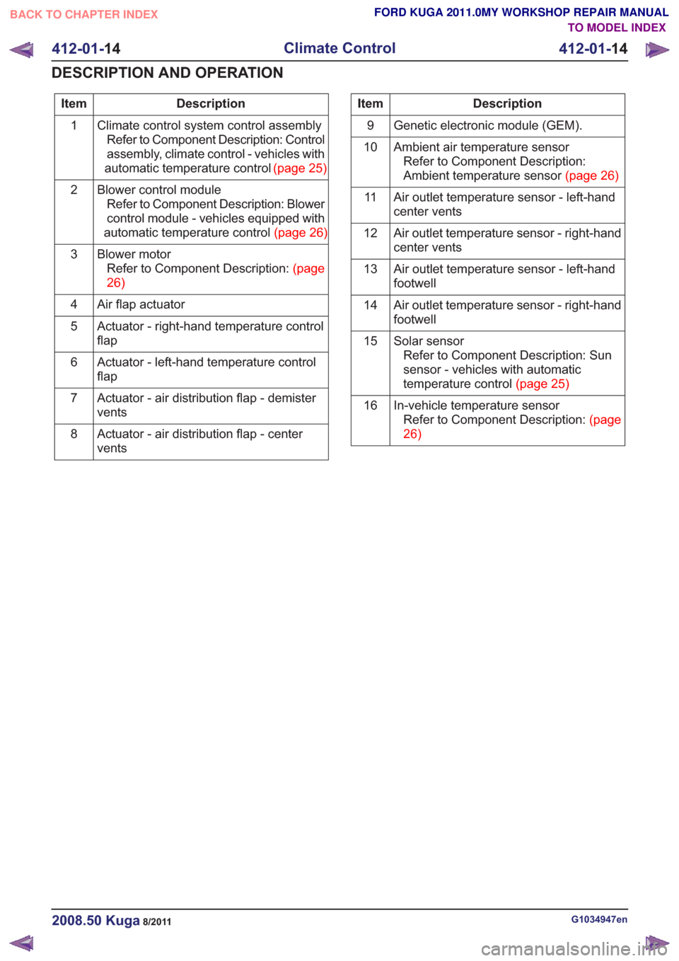
Description
Item
Climate control system control assemblyRefer to Component Description: Control
assembly, climate control - vehicles with
automatictemperaturecontrol (page25)
1
Blower control moduleRefer to Component Description: Blower
control module - vehicles equipped with
automatictemperaturecontrol(page26)
2
Blower motorRefertoComponentDescription:(page
26)
3
Air flap actuator
4
Actuator - right-hand temperature control
flap
5
Actuator - left-hand temperature control
flap
6
Actuator - air distribution flap - demister
vents
7
Actuator - air distribution flap - center
vents
8Description
Item
Genetic electronic module (GEM).
9
Ambient air temperature sensorRefer to Component Description:
Ambienttemperaturesensor(page26)
10
Air outlet temperature sensor - left-hand
center vents
11
Air outlet temperature sensor - right-hand
center vents
12
Air outlet temperature sensor - left-hand
footwell
13
Air outlet temperature sensor - right-hand
footwell
14
Solar sensorRefer to Component Description: Sun
sensor - vehicles with automatic
temperaturecontrol(page25)
15
In-vehicle temperature sensorRefertoComponentDescription:(page
26)
16
G1034947en2008.50 Kuga8/2011
412-01-
14
Climate Control
412-01- 14
DESCRIPTION AND OPERATION
TO MODEL INDEX
BACK TO CHAPTER INDEX
FORD KUGA 2011.0MY WORKSHOP REPAIR MANUAL
Page 2042 of 2057
Climate control system - vehicles with DVD navigation system with a touch screen
17
16
4
1
25
13
14
15
6
9
3
8
7
12
10
E97736
11
MS-CAN
MS-CAN
G1034947en2008.50 Kuga8/2011
412-01-15
Climate Control
412-01- 15
DESCRIPTION AND OPERATION
TO MODEL INDEX
BACK TO CHAPTER INDEX
FORD KUGA 2011.0MY WORKSHOP REPAIR MANUAL
Page 2043 of 2057

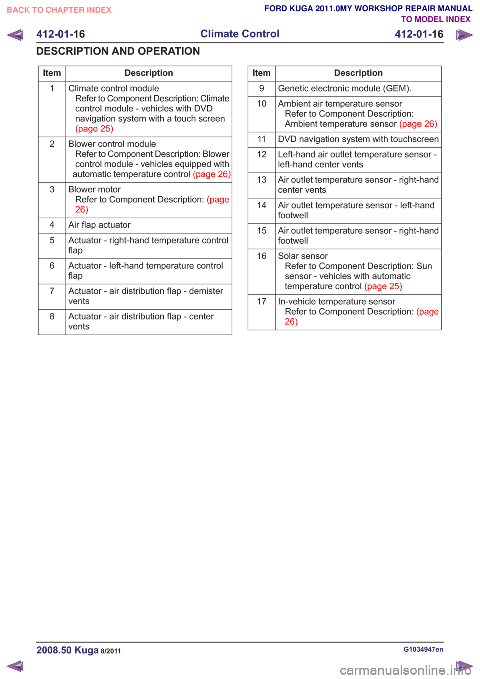
Description
Item
Climate control moduleRefer to Component Description: Climate
control module - vehicles with DVD
navigation system with a touch screen
(page25)
1
Blower control moduleRefer to Component Description: Blower
control module - vehicles equipped with
automatictemperaturecontrol(page26)
2
Blower motorRefertoComponentDescription:(page
26)
3
Air flap actuator
4
Actuator - right-hand temperature control
flap
5
Actuator - left-hand temperature control
flap
6
Actuator - air distribution flap - demister
vents
7
Actuator - air distribution flap - center
vents
8Description
Item
Genetic electronic module (GEM).
9
Ambient air temperature sensorRefer to Component Description:
Ambienttemperaturesensor(page26)
10
DVD navigation system with touchscreen
11
Left-hand air outlet temperature sensor -
left-hand center vents
12
Air outlet temperature sensor - right-hand
center vents
13
Air outlet temperature sensor - left-hand
footwell
14
Air outlet temperature sensor - right-hand
footwell
15
Solar sensorRefer to Component Description: Sun
sensor - vehicles with automatic
temperaturecontrol(page25)
16
In-vehicle temperature sensorRefertoComponentDescription:(page
26)
17
G1034947en2008.50 Kuga8/2011
412-01-
16
Climate Control
412-01- 16
DESCRIPTION AND OPERATION
TO MODEL INDEX
BACK TO CHAPTER INDEX
FORD KUGA 2011.0MY WORKSHOP REPAIR MANUAL
Page 2044 of 2057
Air conditioning system - vehicles with manual temperature control
18
6
7
3
9
2
5
4
E97576
HS-CAN
MS-CAN
Description
Item
Air conditioning compressor
1
Climate control system control assemblyRefer to Component Description: Control
assembly, climate control - vehicles with
manualtemperaturecontrol(page24)
2
Genetic electronic module (GEM).
3Description
Item
Ambient air temperature sensorRefer to Component Description:
Ambienttemperaturesensor(page26)
4
instrument cluster
5
High pressure limiting switch
6
Dual pressure switch
7
G1034947en2008.50 Kuga8/2011
412-01- 17
Climate Control
412-01- 17
DESCRIPTION AND OPERATION
TO MODEL INDEX
BACK TO CHAPTER INDEX
FORD KUGA 2011.0MY WORKSHOP REPAIR MANUAL