2011 FORD KUGA suspension
[x] Cancel search: suspensionPage 190 of 2057

Instrument Cluster
Refer to
Wiring Diagrams Section 413-01, for
schematic and connector information. General Equipment
The Ford approved diagnostic tool
Inspection and Verification
1. Verify the customer concern.
2. Visually inspect for obvious signs of mechanical
or electrical damage.
Visual Inspection Chart Electrical
Mechanical
– Fuse(s)
– Wiring harness
– Electricalconnector(s)
– Instrument cluster
– Light emitting diode(s) (LED)(s)
– Engine oil filter
– Engine oil level
–
Engine coolant level
– Oil pressure switch
– Engine coolant level
– Coolant thermostat
– Engine coolant temperature (ECT)
sensor
– Fuel gauge
– Collapsed or damaged fuel tank
– Recirculation hose
– Fuel tank filler pipe/hose
– Indicated fuel level
– Fuel lines
– Fuel tank filler cap
– Fuel filter (external to the fuel tank)
– Fuel tank
– Door adjustment
3. If an obvious cause for an observed or reported concern is found, correct the cause (if possible)
before proceeding to the next step.
4. NOTE: If none of the following warning indicators are operating correctly this may
indicate a concern with the central junction
box (CJB). If only one or two of the following
warning indicators are not operating
correctly this may indicate an instrument
cluster concern. Verify the following warning indicators are
working correctly:
• Charging.
• Turn signals.
• Headlamps.
5. If the cause is not visually evident, verify the symptom and refer to the diagnostic tab within
the Ford approved diagnostic tool.
Configuration of the Instrument Cluster
The instrument cluster is a programmable module,
which must be configured by selecting the
Programmable Module Installation Routine on the
Ford approved diagnostic tool.
NOTE: When the new instrument cluster has been
configured with the odometer value, its
configuration cannot be decreased or matched. A
new configuration will result in an increase in the
displayed odometer value by a minimum of two
units.
NOTE: The odometer value must be recorded from
the original instrument cluster before removal.
If the odometer value cannot be obtained from
the original instrument cluster (display failure)
the customer should supply the approximate
value.
The following features will need to be configured
when a new instrument cluster is installed:
• Anti-lock Brake System (ABS)
• All wheel drive
• Keyless vehicle entry
• Electronic power assisted steering
• Trip computer
• Voice control
• Parking aid
• Belt minder
• Safety belt not fastened
• Right hand drive
• Overspeed warning
• Reverse warning
• Turbocharger boost pressure
• Speed control
• Auxiliary heater
• Suspension control
• Washer fluid sensor G1054964en
2008.50 Kuga 8/2011 413-01-7
Instrument Cluster
413-01-7
DIAGNOSIS AND TESTINGTO MODEL INDEX
BACK TO CHAPTER INDEX
FORD KUGA 2011.0MY WORKSHOP REPAIR MANUAL
Page 364 of 2057

Headlamp Adjustment
General Equipment
Headlamp Beam Setter
All Vehicles
1. NOTE: Make sure that the tire pressures are to
specification and that the vehicle is unladen.
NOTE: Only use a damp cloth to clean the
headlamp lens to avoid any electrostatic
charging.
Ensure that the adjustment is made with the
suspension set up.
2. Place the vehicle on a level surface.
Vehicles with conventional headlamps
3. Repeatedly operate the headlamp leveling
switch and then set it to "0".
Vehicles with adaptive front lighting
4. Use the diagnostic tool to make certain that the
front wheels are in the straight ahead position.
Vehicles with gas discharge headlamps
5. Calibrate the headlamp leveling system using
the diagnostic tool.
All Vehicles
6. NOTE: Always follow the manufacturer's
instructions when handling the equipment.
Set the measuring screen of the beam setting
equipment to the correct headlamp adjustment
setting.
Refer to: Specifications (417-01 Exterior
Lighting, Specifications).
General Equipment: Headlamp Beam Setter
7. Switch on dipped beam. 8.
Adjust the dipped beams so that the light/dark
boundary touches the horizontal line. 9. NOTE:
It is acceptable for a stray portion of the
low beam to cross the 15° line.
Adjust the headlamps so that the rising line of
the boundary line lies at the intersection of G1066055en
2008.50 Kuga 8/2011 417-01-30
Exterior Lighting
417-01-30
GENERAL PROCEDURESTO MODEL INDEX
BACK TO CHAPTER INDEX
FORD KUGA 2011.0MY WORKSHOP REPAIR MANUALE11721715
Page 392 of 2057

1.
Wiring harness.
2. Component.
5. Check the wiring harness for the following:
• Incorrect routing or installed too tightly.
• Pinched or kinked sections.
• Chafed insulation.
• Security and orientation of retaining clips.
• Damage in areas where the wiring harness is subjected to noise, vibration and harshness
(NVH). For example, transmission or suspension
systems.
6. If any of the conditions listed are present, repair or replace the components as required. TEST
the system for normal operation. If the concern
persists, REFER to the digital multimeter
function of the Ford approved diagnostic tool to
check the integrity of the wiring harness and
electrical connectors. G1021921en
2008.50 Kuga 8/2011 418-02-3
Wiring Harnesses
418-02-3
DIAGNOSIS AND TESTINGTO MODEL INDEX
BACK TO CHAPTER INDEX
FORD KUGA 2011.0MY WORKSHOP REPAIR MANUALE6121621
Page 1158 of 2057
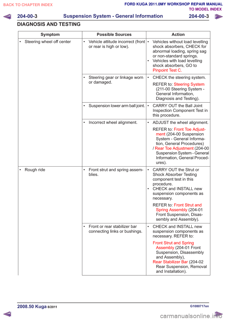
Action
Possible Sources
Symptom
• Vehicles without load levellingshock absorbers, CHECK for
abnormal loading, spring sag
or non-standard springs.
• Vehicles with load levelling shock absorbers, GO to
Pinpoint Test C.
• Vehicle attitude incorrect (front
or rear is high or low).
• Steering wheel off center
• CHECK the steering system.REFER to: Steering System
(211-00 Steering System -
General Information,
Diagnosis and Testing).
• Steering gear or linkage worn
or damaged.
• CARRY OUT the Ball JointInspection Component Test in
this procedure.
• Suspension lower arm ball joint.
• ADJUST the wheel alignment.REFER to: Front Toe Adjust-
ment (204-00 Suspension
System - General Informa-
tion, General Procedures)
/ Rear Toe Adjustment (204-00
Suspension System - General
Information, General Proced-
ures).
• Incorrect wheel alignment.
• CARRY OUT the Strut orShock Absorber Testing
component test in this
procedure.
• CHECK and INSTALL new suspension components as
necessary.
REFER to: Front Strut and
Spring Assembly (204-01
Front Suspension, Disas-
sembly and Assembly).
• Front strut and spring assem-
blies.
• Rough ride
• CHECK and INSTALL newsuspension components as
necessary. REFER to:
Front Strut and Spring Assembly (204-01 Front
Suspension, Disassembly
and Assembly),
Rear Stabilizer Bar (204-02
Rear Suspension, Removal
and Installation).
• Front or rear stabilizer bar
connecting links or bushings.
G1080717en2008.50 Kuga8/2011
204-00- 3
Suspension System - General Information
204-00- 3
DIAGNOSIS AND TESTING
TO MODEL INDEX
BACK TO CHAPTER INDEX
FORD KUGA 2011.0MY WORKSHOP REPAIR MANUAL
Page 1159 of 2057
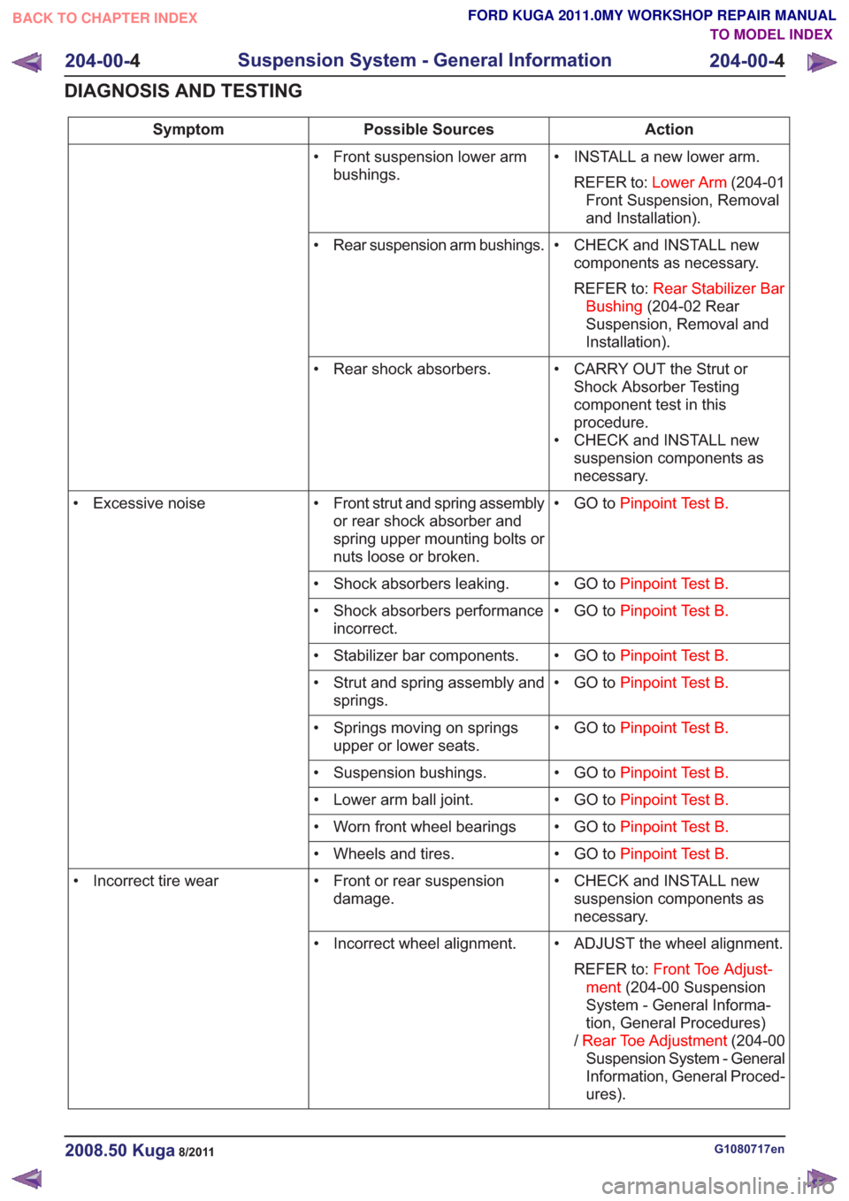
Action
Possible Sources
Symptom
• INSTALL a new lower arm.REFER to: Lower Arm (204-01
Front Suspension, Removal
and Installation).
• Front suspension lower arm
bushings.
• CHECK and INSTALL newcomponents as necessary.
REFER to: Rear Stabilizer Bar
Bushing (204-02 Rear
Suspension, Removal and
Installation).
• Rear suspension arm bushings.
• CARRY OUT the Strut orShock Absorber Testing
component test in this
procedure.
• CHECK and INSTALL new suspension components as
necessary.
• Rear shock absorbers.
• GO toPinpoint Test B.
• Front strut and spring assembly
or rear shock absorber and
spring upper mounting bolts or
nuts loose or broken.
• Excessive noise
• GO toPinpoint Test B.
• Shock absorbers leaking.
• GO toPinpoint Test B.
• Shock absorbers performance
incorrect.
• GO toPinpoint Test B.
• Stabilizer bar components.
• GO toPinpoint Test B.
• Strut and spring assembly and
springs.
• GO toPinpoint Test B.
• Springs moving on springs
upper or lower seats.
• GO toPinpoint Test B.
• Suspension bushings.
• GO toPinpoint Test B.
• Lower arm ball joint.
• GO toPinpoint Test B.
• Worn front wheel bearings
• GO toPinpoint Test B.
• Wheels and tires.
• CHECK and INSTALL newsuspension components as
necessary.
• Front or rear suspension
damage.
• Incorrect tire wear
• ADJUST the wheel alignment.REFER to: Front Toe Adjust-
ment (204-00 Suspension
System - General Informa-
tion, General Procedures)
/ Rear Toe Adjustment (204-00
Suspension System - General
Information, General Proced-
ures).
• Incorrect wheel alignment.
G1080717en2008.50 Kuga8/2011
204-00-
4
Suspension System - General Information
204-00- 4
DIAGNOSIS AND TESTING
TO MODEL INDEX
BACK TO CHAPTER INDEX
FORD KUGA 2011.0MY WORKSHOP REPAIR MANUAL
Page 1160 of 2057
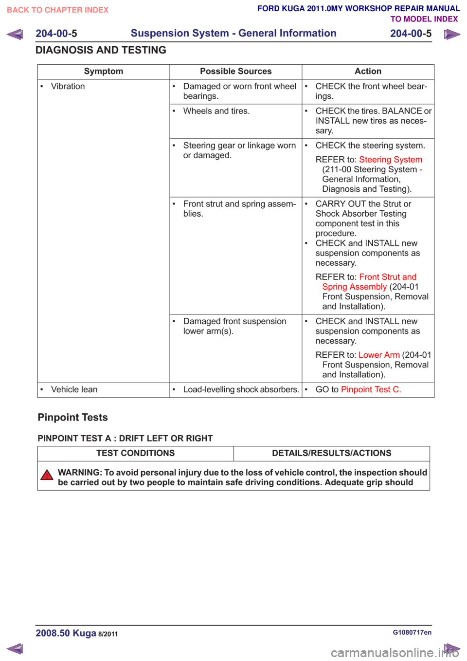
Action
Possible Sources
Symptom
• CHECK the front wheel bear-ings.
• Damaged or worn front wheel
bearings.
• Vibration
• CHECK the tires. BALANCE orINSTALL new tires as neces-
sary.
• Wheels and tires.
• CHECK the steering system.REFER to: Steering System
(211-00 Steering System -
General Information,
Diagnosis and Testing).
• Steering gear or linkage worn
or damaged.
• CARRY OUT the Strut orShock Absorber Testing
component test in this
procedure.
• CHECK and INSTALL new suspension components as
necessary.
REFER to: Front Strut and
Spring Assembly (204-01
Front Suspension, Removal
and Installation).
• Front strut and spring assem-
blies.
• CHECK and INSTALL newsuspension components as
necessary.
REFER to: Lower Arm (204-01
Front Suspension, Removal
and Installation).
• Damaged front suspension
lower arm(s).
• GO toPinpoint Test C.
• Load-levelling shock absorbers.
• Vehicle lean
Pinpoint Tests
PINPOINT TEST A : DRIFT LEFT OR RIGHT
DETAILS/RESULTS/ACTIONS
TEST CONDITIONS
WARNING: To avoid personal injury due to the loss of vehicle control, the inspection should
be carried out by two people to maintain safe driving conditions. Adequate grip should
G1080717en2008.50 Kuga8/2011
204-00- 5
Suspension System - General Information
204-00- 5
DIAGNOSIS AND TESTING
TO MODEL INDEX
BACK TO CHAPTER INDEX
FORD KUGA 2011.0MY WORKSHOP REPAIR MANUAL
Page 1161 of 2057
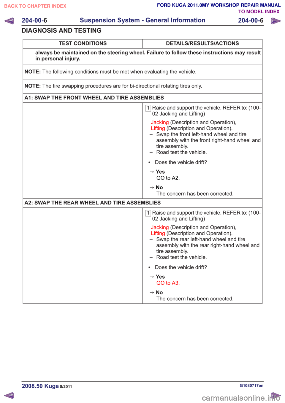
DETAILS/RESULTS/ACTIONS
TEST CONDITIONS
always be maintained on the steering wheel. Failure to follow these instructions may result
in personal injury.
NOTE: The following conditions must be met when evaluating the vehicle.
NOTE: The tire swapping procedures are for bi-directional rotating tires only.
A1: SWAP THE FRONT WHEEL AND TIRE ASSEMBLIES
1 Raise and support the vehicle. REFER to: (100-
02 Jacking and Lifting)
Jacking (Description and Operation),
Lifting (Description and Operation).
– Swap the front left-hand wheel and tire assembly with the front right-hand wheel and
tire assembly.
– Road test the vehicle.
• Does the vehicle drift?
zYe s GO to A2.
zNoThe concern has been corrected.
A2: SWAP THE REAR WHEEL AND TIRE ASSEMBLIES
1 Raise and support the vehicle. REFER to: (100-
02 Jacking and Lifting)
Jacking (Description and Operation),
Lifting (Description and Operation).
– Swap the rear left-hand wheel and tire assembly with the rear right-hand wheel and
tire assembly.
– Road test the vehicle.
• Does the vehicle drift?
zYe s GO to A3.
zNoThe concern has been corrected.
G1080717en2008.50 Kuga8/2011
204-00- 6
Suspension System - General Information
204-00- 6
DIAGNOSIS AND TESTING
TO MODEL INDEX
BACK TO CHAPTER INDEX
FORD KUGA 2011.0MY WORKSHOP REPAIR MANUAL
Page 1162 of 2057
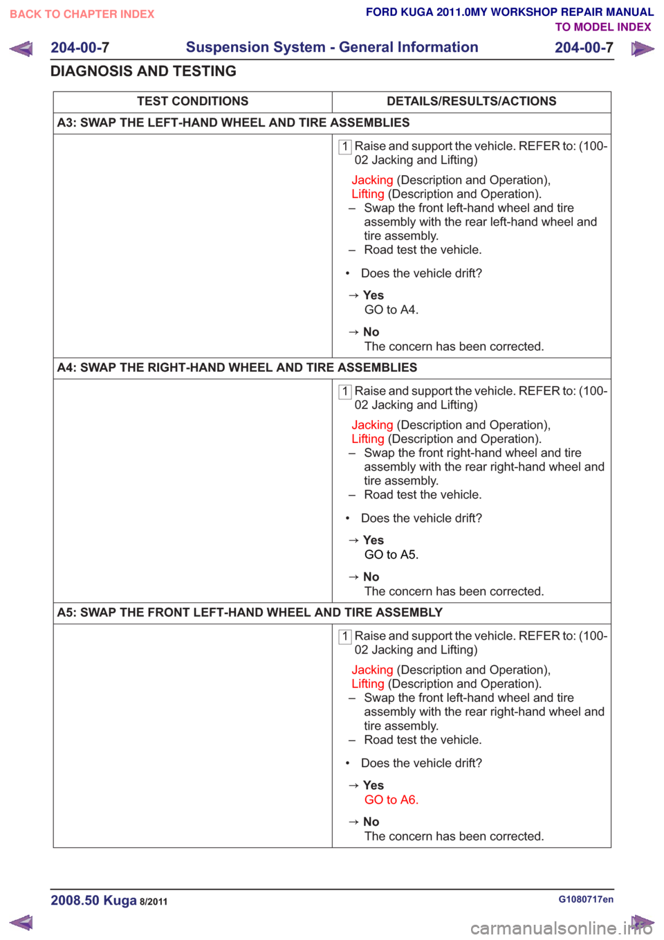
DETAILS/RESULTS/ACTIONS
TEST CONDITIONS
A3: SWAP THE LEFT-HAND WHEEL AND TIRE ASSEMBLIES
1 Raise and support the vehicle. REFER to: (100-
02 Jacking and Lifting)
Jacking (Description and Operation),
Lifting (Description and Operation).
– Swap the front left-hand wheel and tire assembly with the rear left-hand wheel and
tire assembly.
– Road test the vehicle.
• Does the vehicle drift?
zYe s GO to A4.
zNoThe concern has been corrected.
A4: SWAP THE RIGHT-HAND WHEEL AND TIRE ASSEMBLIES
1 Raise and support the vehicle. REFER to: (100-
02 Jacking and Lifting)
Jacking (Description and Operation),
Lifting (Description and Operation).
– Swap the front right-hand wheel and tire assembly with the rear right-hand wheel and
tire assembly.
– Road test the vehicle.
• Does the vehicle drift?
zYe s GO to A5.
zNoThe concern has been corrected.
A5: SWAP THE FRONT LEFT-HAND WHEEL AND TIRE ASSEMBLY
1 Raise and support the vehicle. REFER to: (100-
02 Jacking and Lifting)
Jacking (Description and Operation),
Lifting (Description and Operation).
– Swap the front left-hand wheel and tire assembly with the rear right-hand wheel and
tire assembly.
– Road test the vehicle.
• Does the vehicle drift?
zYe s GO to A6.
zNoThe concern has been corrected.
G1080717en2008.50 Kuga8/2011
204-00- 7
Suspension System - General Information
204-00- 7
DIAGNOSIS AND TESTING
TO MODEL INDEX
BACK TO CHAPTER INDEX
FORD KUGA 2011.0MY WORKSHOP REPAIR MANUAL