2011 FORD KUGA emission
[x] Cancel search: emissionPage 1764 of 2057
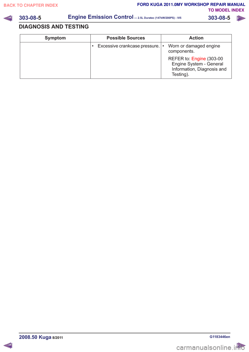
Action
Possible Sources
Symptom
• Worn or damaged enginecomponents.
REFER to: Engine(303-00
Engine System - General
Information, Diagnosis and
Testing).
• Excessive crankcase pressure.
G1183446en2008.50 Kuga8/2011
303-08-
5
Engine Emission Control— 2.5L Duratec (147kW/200PS) - VI5303-08-
5
DIAGNOSIS AND TESTING
TO MODEL INDEX
BACK TO CHAPTER INDEX
FORD KUGA 2011.0MY WORKSHOP REPAIR MANUAL
Page 1768 of 2057
Intake Air Distribution and Filtering
Inspection and Verification
1. Verify the customer concern.
2. Visually inspect for obvious signs of mechanicalor electrical damage.
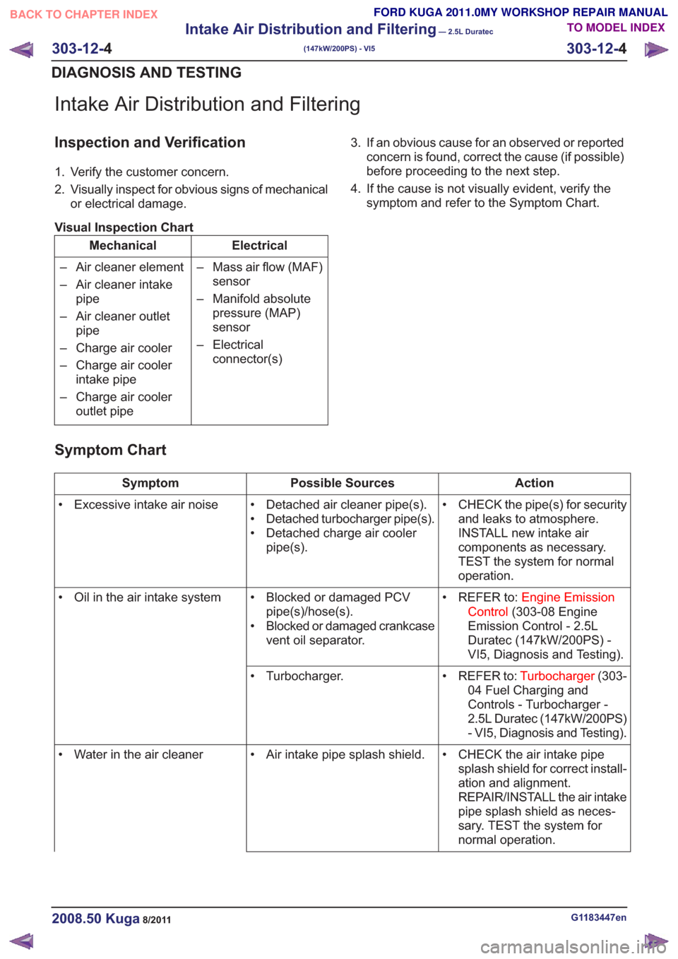
Visual Inspection Chart
Electrical
Mechanical
– Mass air flow (MAF)sensor
– Manifold absolute pressure (MAP)
sensor
– Electrical connector(s)
– Air cleaner element
– Air cleaner intake
pipe
– Air cleaner outlet pipe
– Charge air cooler
– Charge air cooler intake pipe
– Charge air cooler outlet pipe 3. If an obvious cause for an observed or reported
concern is found, correct the cause (if possible)
before proceeding to the next step.
4. If the cause is not visually evident, verify the symptom and refer to the Symptom Chart.
Symptom Chart
Action
Possible Sources
Symptom
• CHECK the pipe(s) for securityand leaks to atmosphere.
INSTALL new intake air
components as necessary.
TEST the system for normal
operation.
• Detached air cleaner pipe(s).
• Detached turbocharger pipe(s).
• Detached charge air cooler
pipe(s).
• Excessive intake air noise
• REFER to:Engine Emission
Control (303-08 Engine
Emission Control - 2.5L
Duratec (147kW/200PS) -
VI5, Diagnosis and Testing).
• Blocked or damaged PCV
pipe(s)/hose(s).
• Blocked or damaged crankcase vent oil separator.
• Oil in the air intake system
• REFER to:Turbocharger(303-
04 Fuel Charging and
Controls - Turbocharger -
2.5L Duratec (147kW/200PS)
- VI5, Diagnosis and Testing).
• Turbocharger.
• CHECK the air intake pipesplash shield for correct install-
ation and alignment.
REPAIR/INSTALL the air intake
pipe splash shield as neces-
sary. TEST the system for
normal operation.
• Air intake pipe splash shield.
• Water in the air cleaner
G1183447en2008.50 Kuga8/2011
303-12- 4
Intake Air Distribution and Filtering
— 2.5L Duratec
(147kW/200PS) - VI5
303-12- 4
DIAGNOSIS AND TESTING
TO MODEL INDEX
BACK TO CHAPTER INDEX
FORD KUGA 2011.0MY WORKSHOP REPAIR MANUAL
Page 1773 of 2057
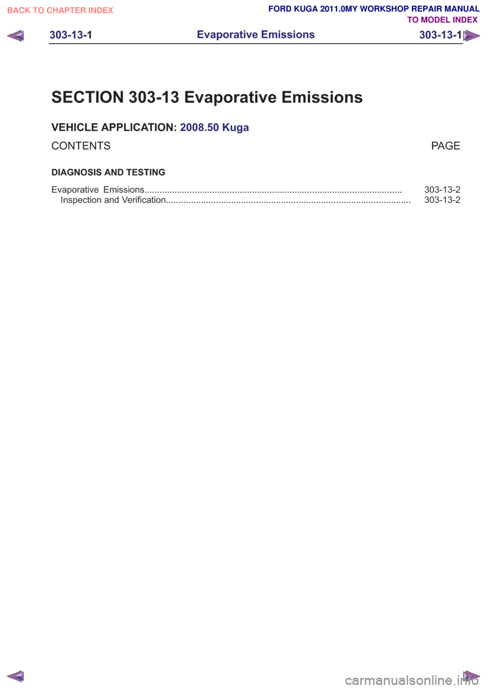
SECTION 303-13 Evaporative Emissions
VEHICLE APPLICATION:2008.50 Kuga
PA G E
CONTENTS
DIAGNOSIS AND TESTING
303-13-2
Evaporative Emissions ........................................................................\
...............................
303-13-2
Inspection and Verification ........................................................................\
..........................
303-13-1
Evaporative Emissions
303-13- 1
.
TO MODEL INDEX
BACK TO CHAPTER INDEX
FORD KUGA 2011.0MY WORKSHOP REPAIR MANUAL
Page 1774 of 2057
Evaporative Emissions
Inspection and Verification
1. Verify the customer concern.
2. Visually inspect for obvious signs of mechanicalor electrical damage.
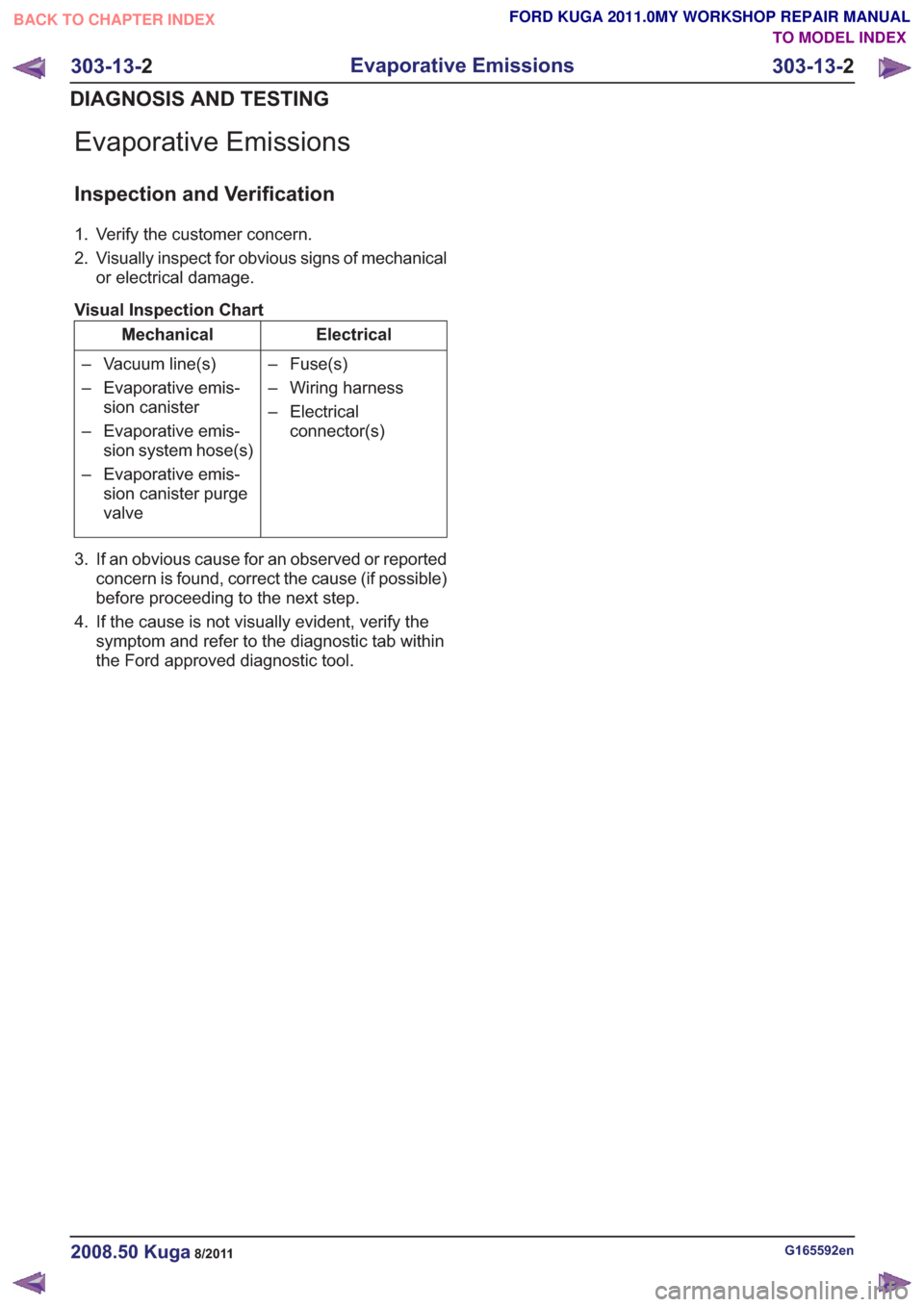
Visual Inspection Chart
Electrical
Mechanical
– Fuse(s)
– Wiring harness
– Electricalconnector(s)
– Vacuum line(s)
– Evaporative emis-
sion canister
– Evaporative emis- sion system hose(s)
– Evaporative emis- sion canister purge
valve
3. If an obvious cause for an observed or reported concern is found, correct the cause (if possible)
before proceeding to the next step.
4. If the cause is not visually evident, verify the symptom and refer to the diagnostic tab within
the Ford approved diagnostic tool.
G165592en2008.50 Kuga8/2011
303-13- 2
Evaporative Emissions
303-13- 2
DIAGNOSIS AND TESTING
TO MODEL INDEX
BACK TO CHAPTER INDEX
FORD KUGA 2011.0MY WORKSHOP REPAIR MANUAL
Page 1778 of 2057
Description
Item
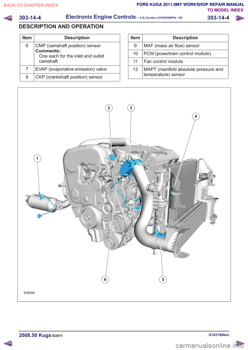
CMP (camshaft position) sensor
Comments:One each for the inlet and outlet
camshaft
6
EVAP (evaporative emission) valve
7
CKP (crankshaft position) sensor
8Description
Item
MAF (mass air flow) sensor
9
PCM (powertrain control module)
10
Fan control module
11
MAPT (manifold absolute pressure and
temperature) sensor
12
E96950
1
23
4
56
G1021906en2008.50 Kuga8/2011
303-14-
4
Electronic Engine Controls— 2.5L Duratec (147kW/200PS) - VI5303-14-
4
DESCRIPTION AND OPERATION
TO MODEL INDEX
BACK TO CHAPTER INDEX
FORD KUGA 2011.0MY WORKSHOP REPAIR MANUAL
Page 1781 of 2057
Electronic Engine Controls – Overview
General overview
Engine Management System
• Bosch ME 9.0 engine management system
• Knock control with two knock sensors
• Electronic Throttle Control Unit.
• Electronic accelerator pedal
• Variable camshaft timing for intake and exhaustcamshafts • Fuel injection supply manifold with combined
fuel pressure and temperature sensor
• Sequential multi-port fuel injection
• Camshaft position (CMP) sensors for intake and exhaust camshafts.
• satisfies the European exhaust emissions standard IV
• EOBD (European On-board Diagnostic) for the monitoring of emissions-related components.
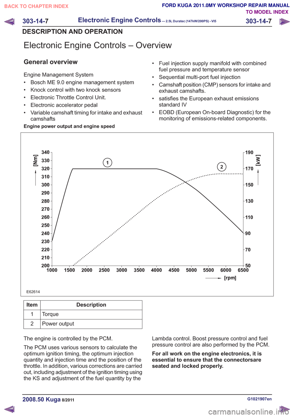
Engine power output and engine speed
2
E62614
1
Description
Item
Torque
1
Power output
2
The engine is controlled by the PCM.
The PCM uses various sensors to calculate the
optimum ignition timing, the optimum injection
quantity and injection time and the position of the
throttle. In addition, various corrections are carried
out, including adjustment of the ignition timing using
the KS and adjustment of the fuel quantity by the Lambda control. Boost pressure control and fuel
pressure control are also performed by the PCM.
For all work on the engine electronics, it is
essential to ensure that the connectorsare
seated and locked properly.
G1021907en2008.50 Kuga8/2011
303-14-
7
Electronic Engine Controls— 2.5L Duratec (147kW/200PS) - VI5303-14-
7
DESCRIPTION AND OPERATION
TO MODEL INDEX
BACK TO CHAPTER INDEX
FORD KUGA 2011.0MY WORKSHOP REPAIR MANUAL
Page 1791 of 2057
• Starting process
• Engine running– Fuel supply to the engine including lambdacontrol
– Ignition setting including knock control
– Idle speed control
– Boost pressure control
– Valve timing via the camshaft adjuster for the intake and exhaust camshafts (including
internal exhaust gas recirculation)
• Refrigerant compressor (activation, deactivation and delivery)
• EVAP purge valve
• Charging system
Fuel is supplied to the engine via a sequential
multi-point injection system. Ignition is performed
by a distributor-less ignition system with one
ignition coil unit for each cylinder.
The PCM optimizes engine power and emissions
at all times by processing the sensor signals and
information received via the CAN databus and
using these for open or closed loop control of the
different variables.
The PCM contains part of the PATS (passive
anti-theft system).
The PCM is supplied with battery voltage via a fuse
in the BJB (battery junction box). This power supply
is needed to ensure that saved data is not lost
when the engine is switched off.
For other power supply requirements, the PCM
switches on a relay in the BJB which is responsible
for supplying power to the PCM and to some
sensors and actuators. Each of these are protected
by fuses in the BJB.
To guarantee optimum engine running at all times,
the PCM has several adaptive (self-learning)
functions. These adapt the output signals to
changing circumstances, such as wear or system
faults.
In some cases a faulty signal is replaced with a
substitute value or limited. A substitute value can
be calculated from other signals or it can be
predefined by the PCM. The substitute value allows
the vehicle to keep on running without the emission
values changing unduly. Depending on the signal
failure, the PCM operates in emergency mode. In
this mode, the engine power and/or the engine
speed is reduced to prevent further damage.
Depending on the faulty signal, a fault code is
stored in the error memory of the PCM. These can be read out using IDS (Integrated Diagnostic
System) via the DLC.
The PCM processes and evaluates the signals
from the sensors. The following sensors send
signals to the PCM:
• CMP sensors
• CKP sensor
• MAF sensor
•KS
• ECT sensor
• TP sensor
• APP sensor
• Broadband HO2S
• Catalyst monitor sensor
• MAPT sensor
• Air conditioning (A/C) pressure sensor
• Alternator
• Fuel temperature and fuel pressure sensor
• Engine oil level, temperature and quality sensor
• Outside air temperature sensor
The following components receive signals from the
PCM:
• Powertrain Control Module relay
• A/C clutch relay
• injectors
• Direct ignition coils
• Cooling fan module
• Throttle control unit
• Camshaft adjuster solenoid valve
• Starter Relay
• EVAP purge valve
• Alternator
• Heating element - broadband HO2S
• Catalyst monitor sensor heating element
• FPDM
• Wastegate control valve
• Air conditioning compressor
The PCM receives the following signals via the
CAN databus:
• APP
•CPP
• BPP
• Vehicle speed.
• Refrigerant compressor request
• PAT S
G1021908en2008.50 Kuga8/2011
303-14-
17
Electronic Engine Controls— 2.5L Duratec (147kW/200PS) - VI5303-14-
17
DESCRIPTION AND OPERATION
TO MODEL INDEX
BACK TO CHAPTER INDEX
FORD KUGA 2011.0MY WORKSHOP REPAIR MANUAL
Page 1793 of 2057
Description
Item
CKP sensor
1
Tooth pitch
2
Flywheel ring gear
3
Reference mark
4
Voltage (sinusoidal-like signal curve)
5Description
Item
60-2 pulses per revolution of the
crankshaft
6
Tooth center
7
Reference mark
8
Tooth pitch
9
The acceleration of the flywheel at each power
stroke results in a change in the CKP signal.
During the power stroke, the combustion pressure
acting on the piston causes an acceleration of the
crankshaft and thus also of the flywheel. This is
apparent in the voltage curve from slightly higher
frequencies and amplitudes of the CKP signal.
Calculation of the ignition angle
Since propagation of the flame front in the air/fuel
mixture always takes the same amount of time, the
ignition of the air/fuel mixture has to take place
earlier or later depending on the engine speed.
The higher the speed, the earlier ignition must
occur. This ensures that maximum combustion
pressure is achieved immediately after Top Dead
Center and that maximum combustion pressure
acts on the piston.
When starting the engine, ignition timing is
determined by the CMP purely from the ignition
map and information on camshaft position (CKP
sensors) and crankshaft position (PCM sensor).
As soon as the engine is running, the following
data are used as a basis for calculating the ignition
angle:
• the engine speed,
• the engine load,
• the coolant temperature and
• the KS signal.
The ignition angle has a major impact on engine
operation. It affects
• engine performance
• exhaust emissions
• fuel consumption,
• combustion knock behavior and
• engine temperature.
The higher the engine load, i.e. the torque demand,
the richer the air/fuel mixture, the longer the
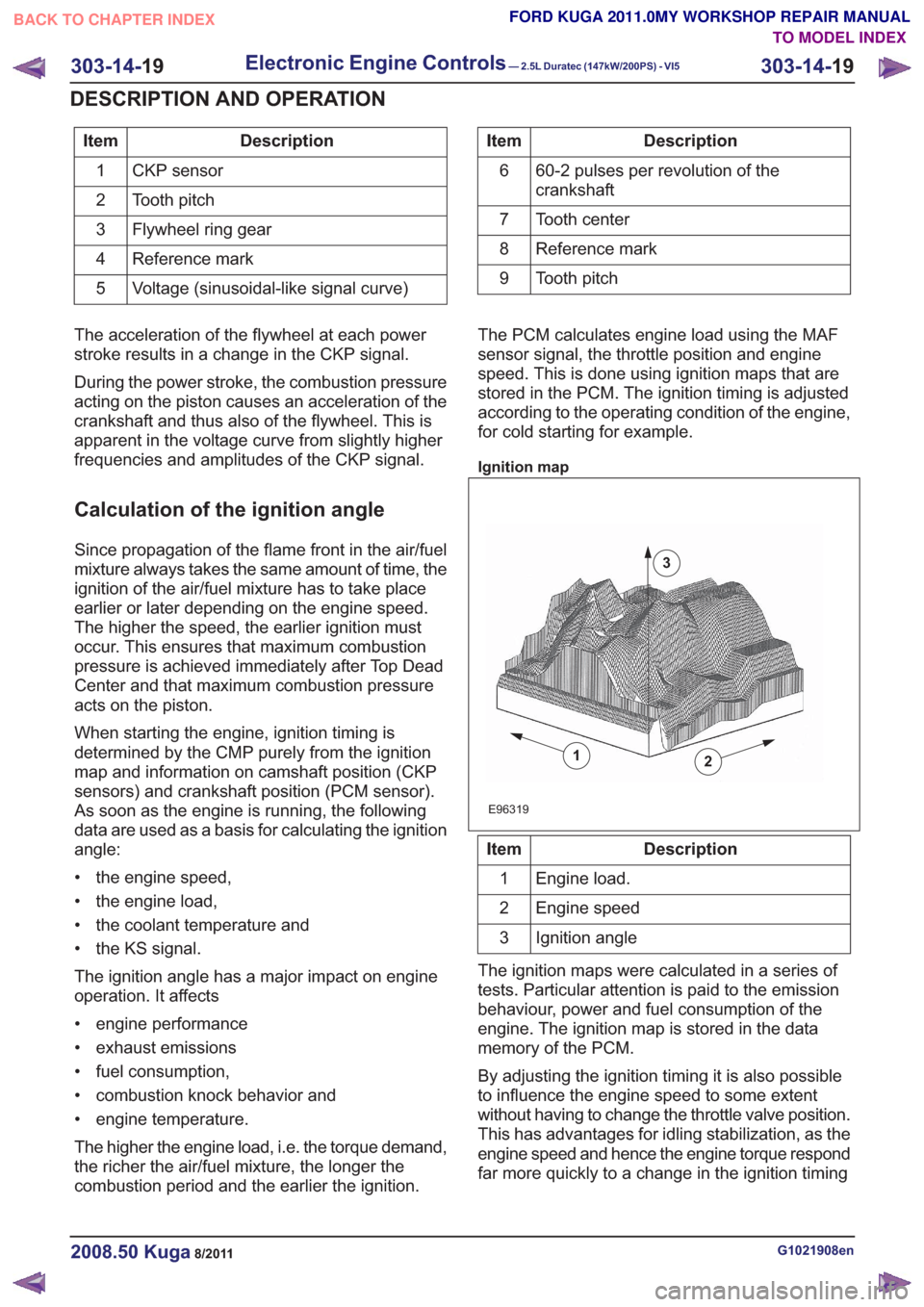
combustion period and the earlier the ignition. The PCM calculates engine load using the MAF
sensor signal, the throttle position and engine
speed. This is done using ignition maps that are
stored in the PCM. The ignition timing is adjusted
according to the operating condition of the engine,
for cold starting for example.
Ignition map
2
E96319
1
3
Description
Item
Engine load.
1
Engine speed
2
Ignition angle
3
The ignition maps were calculated in a series of
tests. Particular attention is paid to the emission
behaviour, power and fuel consumption of the
engine. The ignition map is stored in the data
memory of the PCM.
By adjusting the ignition timing it is also possible
to influence the engine speed to some extent
without having to change the throttle valve position.
This has advantages for idling stabilization, as the
engine speed and hence the engine torque respond
far more quickly to a change in the ignition timing
G1021908en2008.50 Kuga8/2011
303-14- 19
Electronic Engine Controls— 2.5L Duratec (147kW/200PS) - VI5303-14-
19
DESCRIPTION AND OPERATION
TO MODEL INDEX
BACK TO CHAPTER INDEX
FORD KUGA 2011.0MY WORKSHOP REPAIR MANUAL