2011 FORD KUGA check engine light
[x] Cancel search: check engine lightPage 1354 of 2057
4. Remove the vacuum hose from the brakebooster. Manifold vacuum should be available
at the brake booster end of the hose with the
engine at idle speed and the transaxle in the
NEUTRAL position. Make sure that all unused
vacuum outlets are correctly capped, hose
connectors are correctly secured and vacuum
hoses are in good condition. When it is
established that manifold vacuum is available
to the brake booster, connect the vacuum hose
to the brake booster and repeat Step 3. If no
downward movement of the brake pedal is felt,
install a new brake booster.
5. Operate the engine a minimum of 10 seconds at approximately 1200 rpm. Stop the engine and
let the vehicle stand for 10 minutes. Then, apply
the brake pedal with approximately 89 N (20 lb)
force. The pedal feel (brake application) should
be the same as that noted with the engine
operating. If the brake pedal feels hard (no
power assist), install a new vacuum check valve
and then repeat the test. If the brake pedal still
feels hard, install a new brake booster. If the
brake pedal movement feels spongy, bleed the
brake system. REFER to: (206-00 Brake System
- General Information)
Brake System Bleeding (General Procedures),
Brake System Pressure Bleeding (General
Procedures),
Component Bleeding (General Procedures).
Brake Master Cylinder
Usually, the first and strongest indicator of anything
wrong with the braking system is a feeling through
the brake pedal. In diagnosing the condition of the
brake master cylinder, check pedal feel as
evidence of a brake concern. Check for the red
brake warning indicator illumination and the fluid
level in the master cylinder reservoir.
Normal Conditions
The following conditions are considered normal
and are not indications that the brake master
cylinder is in need of service.
– Modern brake systems are not designed to
produce as hard a pedal effort as in the past.
Complaints of light pedal efforts should be compared to pedal efforts of another vehicle, of
the same model and year.
– During normal operation of the brake pedal, the fluid level in the reservoir will rise during brake
pedal application and fall during release. The
net fluid level (i.e., after brake pedal application
and release) will remain unchanged.
– A trace of brake fluid will exists on the brake booster shell below the master cylinder
mounting flange. This results from the normal
lubricating action of the master cylinder bore
end seal.
– The fluid level will fall with brake shoe and lining wear.
Abnormal Conditions
NOTE: Prior to performing any diagnosis, make
sure the brake system warning indicator is
functional.
Changes in brake pedal feel or travel are indicators
that something could be wrong with the braking
system. The diagnostic procedure and techniques
use brake pedal feel, warning indicator illumination
and low brake fluid level as indicators in diagnosing
braking system concerns. The following conditions
are considered abnormal and indicate that the
brake master cylinder is in need of service.
– The brake pedal goes down fast. This could be caused by an external or internal leak.
– The brake pedal eases down slowly. This could be caused by an external or internal leak.
– The brake pedal is low and or feels spongy. This condition may be caused by no fluid in the brake
master cylinder reservoir, reservoir cap vent
holes clogged or air in the hydraulic system.
– The brake pedal effort is excessive. This may be caused by a bind or obstruction in the pedal
or linkage, clogged fluid control valve or
insufficient booster vacuum.
– The rear brakes lock up during light pedal force. This may be caused by incorrect tire pressures,
grease or fluid on the brake shoes and linings,
damaged brake shoes and linings, incorrectly
adjusted parking brake, or damaged or
contaminated brake pressure control valves.
– The brake pedal effort is erratic. This condition could be caused by a brake booster malfunction,
extreme caliper piston knock back or incorrectly
installed brake shoes and linings.
– The red brake warning indicator is ON. This may be caused by low fluid level, ignition wire routing
G1058975en2008.50 Kuga8/2011
206-00- 18
Brake System - General Information
206-00- 18
DIAGNOSIS AND TESTING
TO MODEL INDEX
BACK TO CHAPTER INDEX
FORD KUGA 2011.0MY WORKSHOP REPAIR MANUAL
Page 1429 of 2057
HCU to check for sudden actuation of the brakes.
With the brake pedal pressed, the ABS module
triggers emergency braking if the rate of increase
of hydraulic pressure exceeds the predetermined
limit.
If the brake pedal is pressed so hard that the ABS
becomes active on the front wheels then the ABS
control unit increases the pressure to the rear
wheel brakes up to the ABS intervention threshold.
EBA operation continues until the driver releases
the brake pedal sufficiently for the hydraulic
pressure in the HCU to drop below a threshold
value stored in the ABS module.
Trailer stability control:If the vehicle is ordered
with a trailer coupling then the Trailer Stability
Control function is integrated in the ESP. The ESP
detects snaking when driving with a trailer and
reduces the speed of the vehicle and trailer through
adapted braking and, if necessary, by also reducing
the engine output until the snaking movement of
the trailer is corrected.
Roll-over protection: The ESP dynamically
determines the tipping tendency of the vehicle and
works in conjunction with the EBA system to
prevent the vehicle from tipping over during
dynamic maneuvers like lane changing or while
negotiating bends.
Emergency brake light: The emergency brake
light automatically switches on the hazard flasher
system to warn drivers of other vehicles that
emergency braking is being initiated. Based on a
defined delay value, the ABS/ESP module sends
a signal to the generic electronic module (GEM)
via the CAN data bus. The GEM activates the
hazard flasher system, that then flashes 7 times.
Prerequisites for activation of the emergency brake
light are:
• The speed is higher than 50 km/h.
• The brake pedal is being actuated.
• The deceleration is greater than 9 m/s².
To prevent activation on snow or ice, for example,
the following prerequisites must be met:
• The speed is higher than 50 km/h.
• The brake pedal is being actuated.
• ABS regulation takes place.
• The deceleration is greater than 6 m/s².
Tire pressure monitoring system: The tire
pressure monitoring system used in the Kuga is
able to detect loss of air in a tire at an early stage
and warn the driver. Because it can only compare
the behaviour of the tyres with each other, it is not possible to draw conclusions about the absolute
tyre pressure. It is also not possible to monitor the
spare tyre pressure. In order for the system to
operate correctly, the tyre pressures must be
regularly checked and corrected and the system
subsequently initialised (see below).
The tire pressure monitoring system used here,
depending on the equipment level, is built into the
anti-lock braking system (ABS) as an extra function
and therefore does not have its own sensors.
The ABS module measures the loss of pressure
in the tyres by calculation using the wheel speed
sensors of the ABS system. If a tyre loses
pressure, its diameter decreases and the speed of
the wheel therefore increases. If the ABS module
detects such a loss in pressure, it sends a signal
to the instrument cluster via the CAN bus and a
warning message is displayed in the message
centre. The warning threshold depends among
other things on the dimension of the tyres being
used, the vehicle operating conditions and the
status at the last initialisation. Since neither the
absolute tyre pressure nor the position of the tyre
is known, the pressure of all the tyres must be
checked and the system re-initialised after a tyre
pressure warning. If necessary, the cause of the
loss of pressure must be investigated.
Regular tyre pressure checks are still necessary.
The system must be initialised after a tyre is
changed, winter or summer tyres fitted, the
pressures corrected or adjusted to suit the vehicle
load. This can be done by the driver using the
driver information system. For further information,
see: Owner’s Manual.
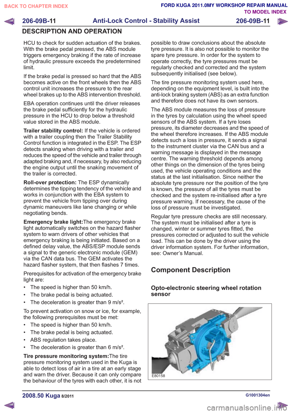
Component Description
Opto-electronic steering wheel rotation
sensor
E80158
G1001304en2008.50 Kuga8/2011
206-09B-
11
Anti-Lock Control - Stability Assist
206-09B- 11
DESCRIPTION AND OPERATION
TO MODEL INDEX
BACK TO CHAPTER INDEX
FORD KUGA 2011.0MY WORKSHOP REPAIR MANUAL
Page 1527 of 2057
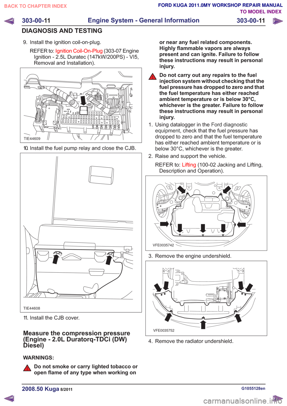
9. Install the ignition coil-on-plug.REFER to: Ignition Coil-On-Plug (303-07 Engine
Ignition - 2.5L Duratec (147kW/200PS) - VI5,
Removal and Installation).
TIE44609
10. Install the fuel pump relay and close the CJB.
TIE44608
11. Install the CJB cover.
Measure the compression pressure
(Engine - 2.0L Duratorq-TDCi (DW)
Diesel)
WARNINGS:
Do not smoke or carry lighted tobacco or
open flame of any type when working on or near any fuel related components.
Highly flammable vapors are always
present and can ignite. Failure to follow
these instructions may result in personal
injury.
Do not carry out any repairs to the fuel
injection system without checking that the
fuel pressure has dropped to zero and that
the fuel temperature has either reached
ambient temperature or is below 30°C,
whichever is the greater. Failure to follow
these instructions may result in personal
injury.
1. Using datalogger in the Ford diagnostic
equipment , check that the fuel pressure has
dropped to zero and that the fuel temperature
has either reached ambient temperature or is
below 30°C, whichever is the greater.
2. Raise and support the vehicle.
REFER to: Lifting(100-02 Jacking and Lifting,
Description and Operation).
VFE0035742
3. Remove the engine undershield.
VFE0035752
4. Remove the radiator undershield.
G1055128en2008.50 Kuga8/2011
303-00- 11
Engine System - General Information
303-00- 11
DIAGNOSIS AND TESTING
TO MODEL INDEX
BACK TO CHAPTER INDEX
FORD KUGA 2011.0MY WORKSHOP REPAIR MANUAL
Page 1783 of 2057
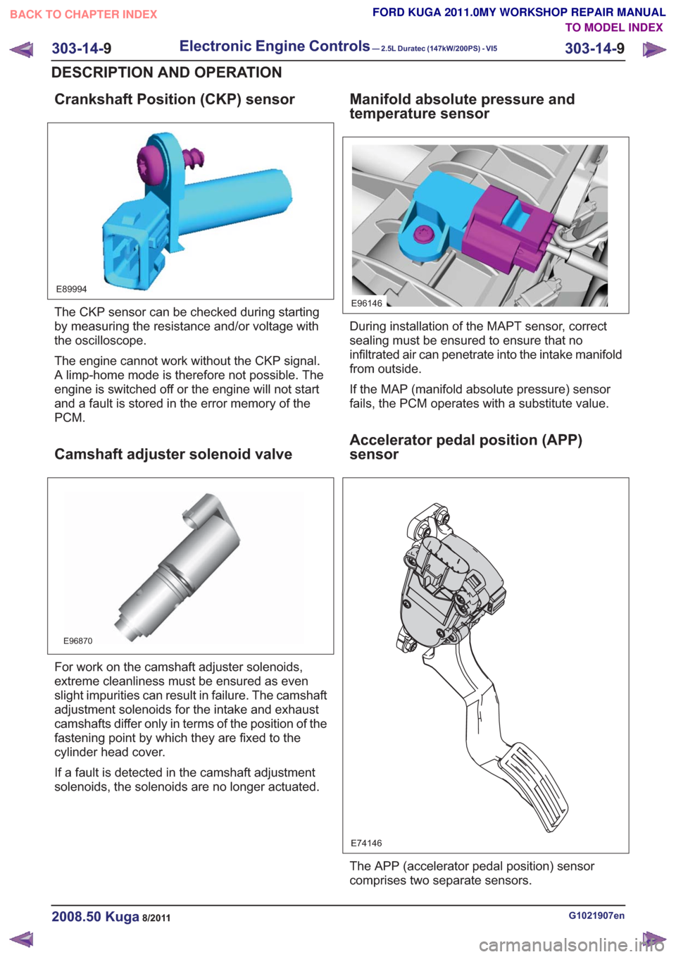
Crankshaft Position (CKP) sensor
E89994
The CKP sensor can be checked during starting
by measuring the resistance and/or voltage with
the oscilloscope.
The engine cannot work without the CKP signal.
A limp-home mode is therefore not possible. The
engine is switched off or the engine will not start
and a fault is stored in the error memory of the
PCM.
Camshaft adjuster solenoid valve
E96870
For work on the camshaft adjuster solenoids,
extreme cleanliness must be ensured as even
slight impurities can result in failure. The camshaft
adjustment solenoids for the intake and exhaust
camshafts differ only in terms of the position of the
fastening point by which they are fixed to the
cylinder head cover.
If a fault is detected in the camshaft adjustment
solenoids, the solenoids are no longer actuated.
Manifold absolute pressure and
temperature sensor
E96146
During installation of the MAPT sensor, correct
sealing must be ensured to ensure that no
infiltrated air can penetrate into the intake manifold
from outside.
If the MAP (manifold absolute pressure) sensor
fails, the PCM operates with a substitute value.
Accelerator pedal position (APP)
sensor
E74146
The APP (accelerator pedal position) sensor
comprises two separate sensors.
G1021907en2008.50 Kuga8/2011
303-14-9
Electronic Engine Controls— 2.5L Duratec (147kW/200PS) - VI5303-14-
9
DESCRIPTION AND OPERATION
TO MODEL INDEX
BACK TO CHAPTER INDEX
FORD KUGA 2011.0MY WORKSHOP REPAIR MANUAL
Page 1784 of 2057
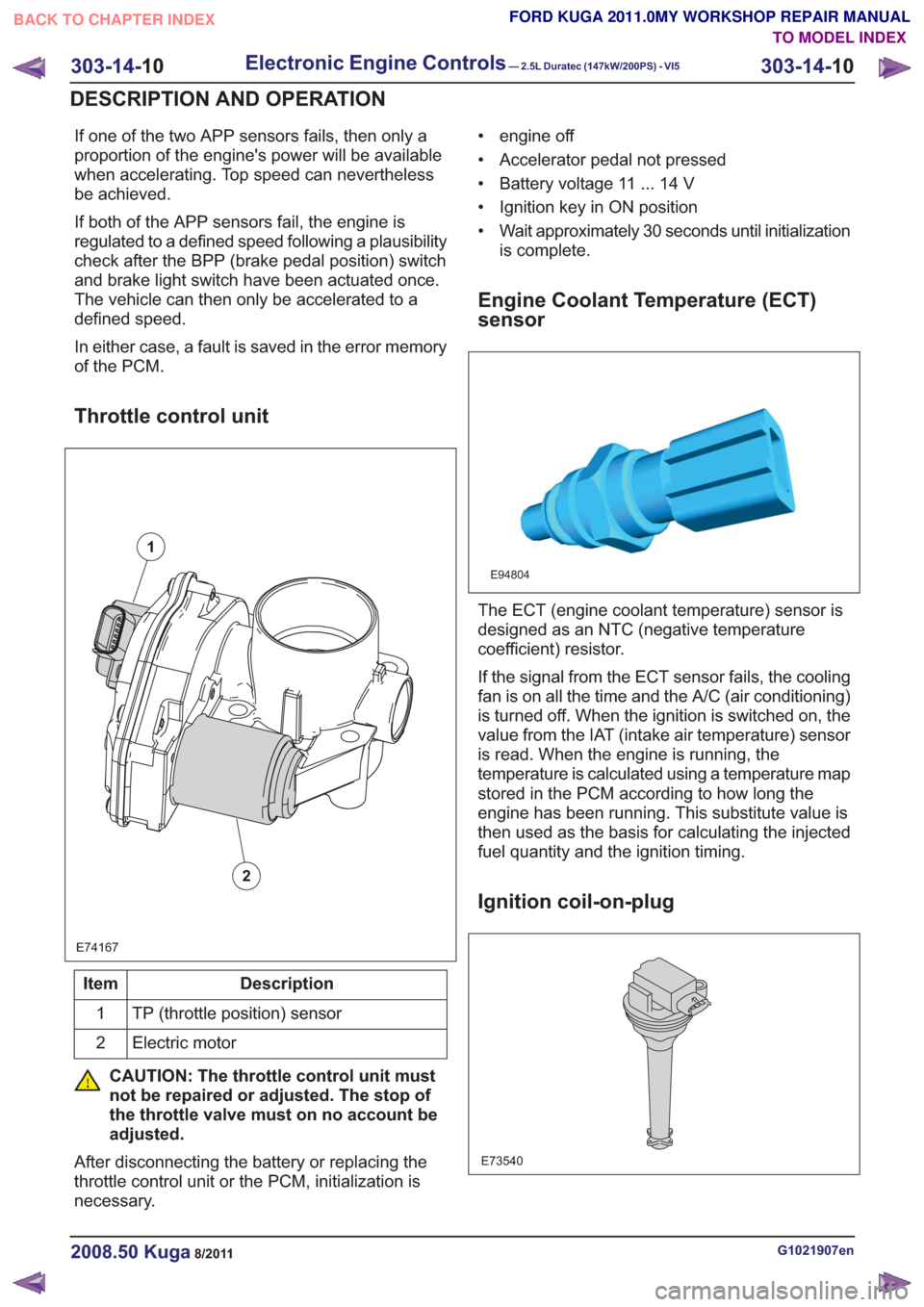
If one of the two APP sensors fails, then only a
proportion of the engine's power will be available
when accelerating. Top speed can nevertheless
be achieved.
If both of the APP sensors fail, the engine is
regulated to a defined speed following a plausibility
check after the BPP (brake pedal position) switch
and brake light switch have been actuated once.
The vehicle can then only be accelerated to a
defined speed.
In either case, a fault is saved in the error memory
of the PCM.
Throttle control unit
E74167
1
2
Description
Item
TP (throttle position) sensor
1
Electric motor
2
CAUTION: The throttle control unit must
not be repaired or adjusted. The stop of
the throttle valve must on no account be
adjusted.
After disconnecting the battery or replacing the
throttle control unit or the PCM, initialization is
necessary. • engine off
• Accelerator pedal not pressed
• Battery voltage 11 ... 14 V
• Ignition key in ON position
• Wait approximately 30 seconds until initialization
is complete.
Engine Coolant Temperature (ECT)
sensor
E94804
The ECT (engine coolant temperature) sensor is
designed as an NTC (negative temperature
coefficient) resistor.
If the signal from the ECT sensor fails, the cooling
fan is on all the time and the A/C (air conditioning)
is turned off. When the ignition is switched on, the
value from the IAT (intake air temperature) sensor
is read. When the engine is running, the
temperature is calculated using a temperature map
stored in the PCM according to how long the
engine has been running. This substitute value is
then used as the basis for calculating the injected
fuel quantity and the ignition timing.
Ignition coil-on-plug
E73540
G1021907en2008.50 Kuga8/2011
303-14- 10
Electronic Engine Controls— 2.5L Duratec (147kW/200PS) - VI5303-14-
10
DESCRIPTION AND OPERATION
TO MODEL INDEX
BACK TO CHAPTER INDEX
FORD KUGA 2011.0MY WORKSHOP REPAIR MANUAL
Page 1796 of 2057
current value is reached. The PCM then
permanently connects the heating element to earth.
The catalyst monitor sensor is used by the PCM
to measure the oxygen content in the exhaust gas
in the TWC. If all the conditions for catalyst
diagnostics are met, based on this information the
PCM can check that the TWC is working
satisfactorily. The information is also used to
improve the air/fuel mixture adjustment.
The catalyst monitor sensor is similar in function
to an HO2S. The signal transmitted by the catalyst
monitor sensor changes sharply if the oxygen
content in the exhaust gas changes. For this
reason, catalyst monitor sensors are also called
"jump lambda sensors".
Fuel tank purging
The EVAP purge valve is only actuated by the PCM
if the coolant temperature is at least 60°C.
Actuation is done ground side by means of a PWM
signal. This makes it possible to have the full range
of opening widths, from fully closed to fully open.
The PCM determines from the operating conditions
when and how wide to open the EVAP tank purge
valve. If the EVAP purge valve is opened, the
engine sucks in ambient air through the activated
charcoal in the evaporative emission canister as
a result of the vacuum in the intake manifold. In
this way the adsorbed hydrocarbons are led to the
combustion chamber of the engine.
The EVAP tank purge valve is not actuated and
system cleaning is interrupted if the engine
switches to idle and/or a closed-loop control
process is initiated.
Power (battery voltage) is supplied via the
Powertrain Control Module relay in the BJB. The
solenoid coil resistance is between 17 and 24 ohms
at 20°C.
Engine speed control
The APP sensor provides the PCM with information
about the driver's request for acceleration.
The throttle control unit receives a corresponding
input signal from the PCM. An electric motor then
moves the throttle valve shaft by means of a set
of gears. The position of the throttle is continuously
recorded by the TP sensor. Information on throttle
position is processed and monitored by the PCM.
The TP sensor comprises two potentiometers.
These work in opposite ways to each other. In one
potentiometer, the resistance increases when the
throttle is opened, in the other it decreases. Thisallows the operation of the potentiometers to be
checked. The signal from the TP sensor is
amplified in the lower range (idle to a quarter open)
by the PCM to enable more precise control of the
throttle in this range. This is necessary because
the engine is very sensitive to changes in throttle
angle in this throttle opening range.
With the throttle valve position kept constant, the
ignition angle and the injected fuel quantity are
then varied to meet the torque demands.
Depending on the operating state of the engine, a
change in the position of the throttle flap may not
be necessary when the APP sensor changes.
If a fault develops in the throttle control unit, a
standby function is executed. This standby function
allows a slight opening of the throttle flap, so that
enough air passes through to allow limited engine
operation. For this purpose, there is a throttle flap
adjustment screw on the throttle housing. The
return spring closes the throttle flap until the stop
of the toothed segment touches the stop screw. In
this way a defined throttle flap gap is formed for
limp home mode.
The stop screw has a spring loaded pin, which
holds the throttle flap open for limp home mode.
In normal operating mode, this spring loaded pin
is pushed in by the force of the electric motor when
the throttle flap must be closed past the limp home
position (e.g. for idle speed control or overrun
shutoff).
Oil monitoring
The engine does not have an oil pressure
switch.
The oil level and oil quality are calculated.
Calculating the engine oil level
The oil level is determined by continuous
measurement of the capacitance (i.e. the ability to
store an electrical charge) between the two
capacitive elements of the engine oil
level/temperature/quality sensor. The different oil
levels cause the capacitance between the elements
to change. The data are recorded by the PCM and
converted into an oil level value. Temporary
fluctuations in oil level are automatically filtered out
by the PCM.
Calculating oil quality
The PCM calculates the oil quality from the oil level
measurement and the oil temperature measured
by the sensor, plus the engine speed and the
average fuel consumption. The driver is informed
about when an oil change is due.
G1021908en2008.50 Kuga8/2011
303-14- 22
Electronic Engine Controls— 2.5L Duratec (147kW/200PS) - VI5303-14-
22
DESCRIPTION AND OPERATION
TO MODEL INDEX
BACK TO CHAPTER INDEX
FORD KUGA 2011.0MY WORKSHOP REPAIR MANUAL
Page 1865 of 2057
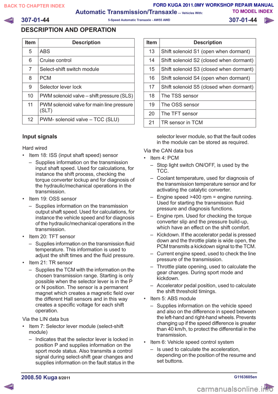
Description
Item
ABS5
Cruise control
6
Select-shift switch module
7
PCM
8
Selector lever lock
9
PWM solenoid valve – shift pressure (SLS)
10
PWM solenoid valve for main line pressure
(SLT)
11
PWM- solenoid valve – TCC (SLU)
12Description
Item
Shift solenoid S1 (open when dormant)
13
Shift solenoid S2 (closed when dormant)
14
Shift solenoid S3 (closed when dormant)
15
Shift solenoid S4 (open when dormant)
16
Shift solenoid S5 (closed when dormant)
17
The TSS sensor
18
The OSS sensor
19
The TFT sensor
20
TR sensor in TCM
21
Input signals
Hard wired
• Item 18: ISS (input shaft speed) sensor
– Supplies information on the transmissioninput shaft speed. Used for calculations, for
instance the shift process, checking the
torque converter lockup and for diagnosis of
the hydraulic/mechanical operations in the
transmission.
• Item 19: OSS sensor – Supplies information on the transmissionoutput shaft speed. Used for calculations, for
instance the vehicle speed and for diagnosis
of the hydraulic/mechanical operations in the
transmission.
• Item 20: TFT sensor – Supplies information on the transmission fluidtemperature. This information is used to
adjust the shift times and the fluid pressure.
• Item 21: TR sensor – Supplies the TCM with the information on thechosen transmission range. Starting is only
possible when the selector lever is in the P
or N position. The sensor is a permanent
magnet which creates a magnetic field over
the different Hall sensors and in this way
creates a specific voltage for each shift
operation.
Via the LIN data bus
• Item 7: Selector lever module (select-shift module)
– Indicates that the selector lever is locked inposition P and supplies information on the
sport mode status. Also transmits a control
signal during select-shift gear changes and
supplies information on the fault status in the selector lever module, so that the fault codes
in the module can be stored as required.
Via the CAN data bus
• Item 4: PCM – Stop light switch ON/OFF, is used by theTCC.
– Coolant temperature, used for diagnosis of the transmission temperature sensor and for
activating the catalytic converter.
– Engine speed >400 rpm = engine running. Used for starting the transmission fluid
pressure and diagnosis functions.
– Engine rpm. Used for checking the torque converter slip and the pressure build-up,
which have an effect on the shift comfort.
– Kickdown. If the accelerator pedal is pressed down and the throttle plate is wide open, the
PCM transmits a kickdown signal to the TCM.
– Current engine speed, used to check the line pressure of the transmission.
– Throttle plate opening, used to calculate the gear changes. During sport mode and
kickdown.
– Accelerator pedal position, used to calculate the shift threshold timings.
• Item 5: ABS module – Supplies information on the vehicle speedand also on the difference in speed between
the left-hand and right-hand wheels. Prevents
changing up if the speed difference is greater
than 40 km/h, to protect the differential in the
transmission.
• Item 6: Vehicle speed control system – Is used to calculate the acceleration,depending on the position of the resume and
set buttons.
G1163605en2008.50 Kuga8/2011
307-01- 44
Automatic Transmission/Transaxle
— Vehicles With:
5-Speed Automatic Transaxle - AW55 AWD
307-01- 44
DESCRIPTION AND OPERATION
TO MODEL INDEX
BACK TO CHAPTER INDEX
FORD KUGA 2011.0MY WORKSHOP REPAIR MANUAL
Page 1866 of 2057
Output signals
Hard wired
• Item 8: PCM– Start inhibitor. Supplies the PCM with a signalthat indicates whether the engine can be
started or not.
• Item 9: Selector lever module (select-shift module)
– Controls the solenoid switch in the selectorlever unit.
• Position 10: PWM solenoid valve – shift pressure (SLS)
– Matches the line pressure to a shift pressureand is activated for certain gears.
• Position 11: PWM solenoid valve – main line pressure (SLT)
– Adjusts the linear line pressure for gearchanges without jolts.
• Position 12: PWM- solenoid valve – TCC (SLU) – Matches the line pressure to a torqueconverter lock-up pressure. Is also used for
certain gearshifts.
• Items 13 - 17: Shift solenoids S1 – S5 – The TCM checks which gear is engaged asthe solenoids become active in different
patterns.
Via the LIN data bus
• Item 7: Selector lever module (select-shift module)
– The TCM transmits a signal to the selectorlever module which activates the LED (light
emitting diode) in the selector mechanism
assembly according to the selector lever
position. Via the CAN data bus
• Item 2: GEM
– The selector lever module transmits a signalvia the TCM, which indicates that the selector
lever is locked in position P. The GEM uses
this information to control the ignition switch
key inhibit function.
– The TCM transmits a signal via the GEM to activate the back-up lamps.
• Item 3: Instrument Cluster – Current selector lever position. Used toindicate the selector lever position in the
instrument cluster.
– Check the warning lamps via the GEM. In the event of a fault, the general warning lamp
lights.
– Text messages in the instrument cluster via the GEM. The driver receives various
malfunction messages from the TCM.
– The TCM transmits signals on the CAN data bus to the PCM so that the MIL lights up in
the event of emissions-related faults.
• Item 4: PCM – Transmission fluid temperature, used tocompensate for increased loads at low fluid
temperatures.
– Gear selected, used by the engine so that it can compensate for different loads.
– Torque converter lockup, used by the engine so that it can compensate for different loads.
– Next gear planned by the TCM, used by the engine to compensate for different loads.
– Requirement for a reduced engine torque during gear shifts, the engine reduces the
engine torque during gear shifts.
– Torque limiting requirement, the engine limits the engine torque according to the gear
engaged.
• Item 5: ABS module – Current gear, used to transmit a signal, notfor shift control.
– Vehicle speed, used as reserve.
Control valve assembly
G1163605en2008.50 Kuga8/2011
307-01- 45
Automatic Transmission/Transaxle
— Vehicles With:
5-Speed Automatic Transaxle - AW55 AWD
307-01- 45
DESCRIPTION AND OPERATION
TO MODEL INDEX
BACK TO CHAPTER INDEX
FORD KUGA 2011.0MY WORKSHOP REPAIR MANUAL