2011 FORD KUGA air hose
[x] Cancel search: air hosePage 72 of 2057

Body Repair Health and Safety and General Precautions
General
Appropriate repair methods and carrying out repair
and paint jobs correctly is particularly important to
the operating safety of vehicles and the safety of
people.
WARNING: There is danger of injury
through:
• High voltage when electrical welding. – Do not perform welding work in a dampenvironment or on a wet substrate. Use
suitable insulation underneath.
• Welding spatter and UV radiation. – Wear protective clothing, gloves and weldingmask or welding goggles.
• Fire, explosion and hot surfaces in the work area.
– Always have a suitable fire extinguisheravailable when using welding or heating
equipment.
– Remove flammable substances from the danger area. Remove the fuel tank and fuel
pipes and hoses.
– Welding and grinding near the battery presents the danger of explosion. Remove
the battery before you start working.
– During paint work there is an increased danger of fire or explosion. Prevent any
sparks being created. Fire, open light and
smoking are forbidden.
– Always ventilate the workplace well and use an extraction system.
– Wear protective footwear made from anti-static material.
– Only use tools made of wood, brass or copper to clean stands and extraction ducts.
Do not use tools made of steel.
– Only fill or decant paint materials in a specially marked area. • Inhalation and/or absorption through the skin of
harmful substances.
– Welding fumes grinding dusts and solventvapours can be extremely harmful to the
health.
– Sealants, underbody protection and paint residues must not be burnt down with an
unshielded flame, as this will produce harmful
substances.
– Always ventilate the workplace well and use an extraction system.
– Wear protective clothing.
• Pyrotechnic components. – Disconnect the battery negative clamp andcover the battery terminal.
– Remove any airbag components.
• Noise – Cutting, grinding and alignment work cancause a noise level over 85 dB (A).
– Always wear ear protection.
• High Forces. – The various body areas are subject to veryhigh forces during realignment work. Should
any component suddenly become detached
during this process, there is a very great
danger of injury.
– Pulling chains and pulling shackles must be secured with arrester cables.
As well as these general instructions on the
dangers in body and paint shops, you must
observe:
• All valid local national and international regulations governing Health and Safety at Work
• Safety instructions of material equipment and tool manufacturers
For additional information, refer to: (100-00 General
Information) Solvents, Sealants and Adhesives (Description
and Operation),
Air Conditioning (A/C) System Health and Safety Precautions (Description and Operation),
Supplemental Restraint System (SRS) Health and Safety Precautions (Description and
Operation).
G963390en2008.50 Kuga8/2011
100-00- 67
General Information
100-00- 67
DESCRIPTION AND OPERATION
TO MODEL INDEX
BACK TO CHAPTER INDEX
FORD KUGA 2011.0MY WORKSHOP REPAIR MANUAL
Page 73 of 2057

Personal protection
Besides the body and limbs, several organs vital
to life are in very particular danger. Because
damage is mostly irreparable, special attention and
comprehensive protection is necessary.
Protective equipment
Always use the appropriate protective equipment:
• Protective helmet or welding mask
• Breathing protection
• Protective clothes gloves and safety boots
• Ear defenders
• Extraction systems
Always carry out an operational check on your
protective equipment every time before you start
working!
Breathing protection
WARNING: Vapor or spray mist containing
isocyanates as a paint base or hardener
can cause toxic respiratory disease
(conditions similar to asthma) leading to
permanent damage, even when inhaled in
the lowest concentrations
The instructions for use provided by the
manufacturer must be observed when working with
breathing protection equipment.
During painting work and in the preparations for
painting, gases, vapors, mists or dusts can appear
in dangerous concentrations.
Breathing protection devices which are
independent of the local atmosphere are most
suitable.
In these types of isolation systems, a compressed
air hose carries natural air from the compressor
line into the protective mask. During supply, the
air undergoes pressure reduction, water removal,
fine filtration and usually warming to natural breath
temperature.
E59518
Description
Item
Protective hood with fresh air supply
1
Protective clothing
2
Protective gloves
3
Protective footwear
4
Only for short periods of work or minimal
concentrations of hazardous substances breathing
protection devices with a combination filter is
suitable as breathing protection equipment.
G963390en2008.50 Kuga8/2011
100-00- 68
General Information
100-00- 68
DESCRIPTION AND OPERATION
TO MODEL INDEX
BACK TO CHAPTER INDEX
FORD KUGA 2011.0MY WORKSHOP REPAIR MANUAL
Page 91 of 2057

Action
Possible Sources
Symptom
Certain amount of noise level
acceptable, not a safety critical
item.
Steering wheel to shroud interfer-
ence.
Power steering system grinding
noise – an abrasive noise (like
sand paper rubbing against
wood) occurs between moving
components such as steering
wheel and the steering column
shroud. Certain amount of noise level
acceptable, not a safety critical
item.
Steering column bearing.
CHECK if floor covering is
obstructing the steering gear
pinion.
Foreign material in contact with
the steering column shaft.
CHECK the installation of the
floor seal.
CHECK the clockspring and
secure if necessary.
REFER to:Clockspring (501-20
Supplemental Restraint
System, Removal and Installa-
tion).
Clockspring.
Power Steering Zip Noise
Action
Possible Sources
Symptom
Certain amount of noise level
acceptable, not a safety critical
item.
High viscosity of power steering
fluid at low temperature.
Power steering system zip noise
– occurs when hydraulic fluid
does not flow freely through the
power steering pump supply hose
from steering fluid reservoir to
power steering pump causing
cavitation at the pump. Zip is
primarily a cold weather start-up
phenomenon (below -10°C). BLEED the power steering
system.
REFER to:
Power Steering
System Vacuum Bleeding (211-
00 Steering System - General
Information, General Proced-
ures).
Aeration of the power steering
fluid.
Driveline Noise and Vibration
Action
Possible Sources
Symptom
GO toPinpoint Test A.
• Wheel end vibration.
• Engine/transmission.
Shake and vibration while driving
GO toPinpoint Test B.
• Air cleaner.
• Power assisted steering.
• Powertrain.
• Powertrain/drivetrain mounts.
• Exhaust system.
Tip-in moan
G37349en2008.50 Kuga8/2011
100-04-
13
Noise, Vibration and Harshness
100-04- 13
DIAGNOSIS AND TESTING
TO MODEL INDEX
BACK TO CHAPTER INDEX
FORD KUGA 2011.0MY WORKSHOP REPAIR MANUAL
Page 92 of 2057

Action
Possible Sources
Symptom
GO toPinpoint Test C.
• Cable(s)/hose(s).
• Powertrain/drivetrain mounts.
• Exhaust system.
• Belt/pulleys.
Idle boom/shake/vibration/
shudder
Suspension Noise and Vibration
Action
Possible Sources
Symptom
GO toPinpoint Test D.
• Suspension.
• Wheel bearings.
Wheel end vibration analysis
GO toPinpoint Test E.
• Trim panels.
• Air conditioning (A/C) system.
• Accessories.
Non-axle noise
Pinpoint Tests
NOTE:
These Pinpoint Tests are designed to take
the technician through a step-by-step diagnosis
procedure to determine the cause of a condition.
It may not always be necessary to follow the chart
to its conclusion. Carry out only the pinpoint test steps necessary to correct the condition. Then
check the operation of the system to make sure
the condition has been corrected.
After verifying that the condition has been
corrected, make sure all components removed
have been installed.
PINPOINT TEST A : SHAKE AND VIBRATION WHILE DRIVING
DETAILS/RESULTS/ACTIONS
TEST CONDITIONS
A1: NEUTRAL COAST
1 Carry out the neutral coast test.
• Does the vibration disappear during the neutral coast test?
zYe s
GO to A2.
zNoGO to Pinpoint Test D.
A2: CHECK THE POWERTRAIN/DRIVETRAIN MOUNTS
1 Carry out the powertrain/drivetrain mount neut-
ralizing procedure
• Are the mounts OK?
zYe s Vehicle condition corrected. ROAD TEST as
necessary.
zNoINSTALL new powertrain/drivetrain mounts
as necessary. ROAD TEST as necessary.
G37349en2008.50 Kuga8/2011
100-04- 14
Noise, Vibration and Harshness
100-04- 14
DIAGNOSIS AND TESTING
TO MODEL INDEX
BACK TO CHAPTER INDEX
FORD KUGA 2011.0MY WORKSHOP REPAIR MANUAL
Page 94 of 2057

DETAILS/RESULTS/ACTIONS
TEST CONDITIONS
B4: CHECK THE POWERTRAIN/DRIVETRAIN MOUNTS
1 Carry out the powertrain/drivetrain mount neut-
ralizing procedure
• Are the powertrain/drivetrain mounts OK?
zYe s Vehicle condition corrected. ROAD TEST as
necessary.
zNoINSTALL new powertrain/drivetrain mounts
as necessary. ROAD TEST as necessary.
PINPOINT TEST C : IDLE BOOM/SHAKE/VIBRATION/SHUDDER
DETAILS/RESULTS/ACTIONS
TEST CONDITIONS
C1: CHECK THE CABLE/HOSES
1 Check the engine compartment for any
component that may have a touch condition
between the engine and body or chassis. For
example: control cable, air conditioning (A/C)
hoses, acceleration cable.
• Are the components OK?
zYe s GO to C2 .
zNo
REPAIR or INSTALL new components as
necessary. ROAD TEST as necessary.
C2: CHECK THE ENGINE COOLING RADIATOR
1 Check the engine cooling radiator mountings
and bushings for security and condition. Check
the radiator installation for any component that
may have a touch condition.
• Is the installation and bushings OK?
zYe s GO to C3 .
zNo
REPAIR or INSTALL new components as
necessary. ROAD TEST as necessary.
G37349en2008.50 Kuga8/2011
100-04- 16
Noise, Vibration and Harshness
100-04- 16
DIAGNOSIS AND TESTING
TO MODEL INDEX
BACK TO CHAPTER INDEX
FORD KUGA 2011.0MY WORKSHOP REPAIR MANUAL
Page 170 of 2057

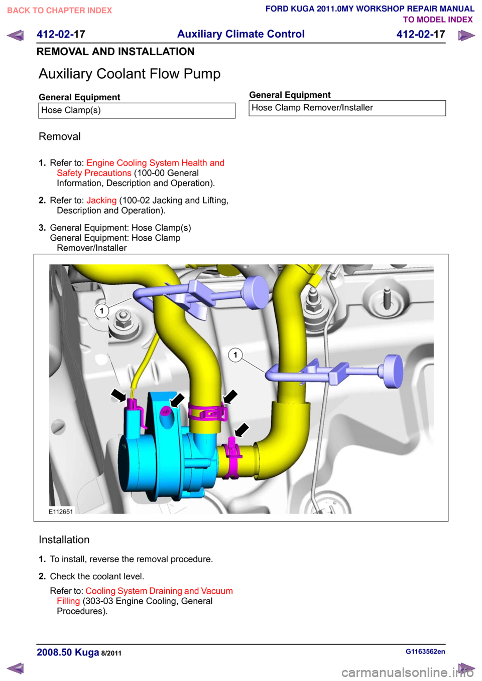
Auxiliary Coolant Flow Pump
General Equipment
Hose Clamp(s) General Equipment
Hose Clamp Remover/Installer
Removal
1. Refer to: Engine Cooling System Health and
Safety Precautions (100-00 General
Information, Description and Operation).
2. Refer to: Jacking(100-02 Jacking and Lifting,
Description and Operation).
3. General Equipment: Hose Clamp(s)
General Equipment: Hose Clamp
Remover/Installer Installation
1.
To install, reverse the removal procedure.
2. Check the coolant level.
Refer to: Cooling System Draining and Vacuum
Filling (303-03 Engine Cooling, General
Procedures). G1163562en
2008.50 Kuga 8/2011 412-02-17
Auxiliary Climate Control
412-02-17
REMOVAL AND INSTALLATIONTO MODEL INDEX
BACK TO CHAPTER INDEX
FORD KUGA 2011.0MY WORKSHOP REPAIR MANUAL11E112651
Page 174 of 2057

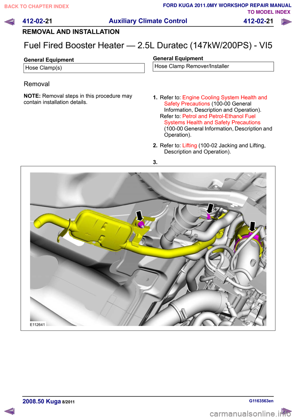
Fuel Fired Booster Heater — 2.5L Duratec (147kW/200PS) - VI5
General Equipment
Hose Clamp(s) General Equipment
Hose Clamp Remover/Installer
Removal
NOTE: Removal steps in this procedure may
contain installation details. 1.
Refer to: Engine Cooling System Health and
Safety Precautions (100-00 General
Information, Description and Operation).
Refer to: Petrol and Petrol-Ethanol Fuel
Systems Health and Safety Precautions
(100-00 General Information, Description and
Operation).
2. Refer to: Lifting(100-02 Jacking and Lifting,
Description and Operation).
3. G1163563en
2008.50 Kuga 8/2011 412-02-21
Auxiliary Climate Control
412-02-21
REMOVAL AND INSTALLATIONTO MODEL INDEX
BACK TO CHAPTER INDEX
FORD KUGA 2011.0MY WORKSHOP REPAIR MANUALE112641
Page 190 of 2057

Instrument Cluster
Refer to
Wiring Diagrams Section 413-01, for
schematic and connector information. General Equipment
The Ford approved diagnostic tool
Inspection and Verification
1. Verify the customer concern.
2. Visually inspect for obvious signs of mechanical
or electrical damage.
Visual Inspection Chart Electrical
Mechanical
– Fuse(s)
– Wiring harness
– Electricalconnector(s)
– Instrument cluster
– Light emitting diode(s) (LED)(s)
– Engine oil filter
– Engine oil level
–
Engine coolant level
– Oil pressure switch
– Engine coolant level
– Coolant thermostat
– Engine coolant temperature (ECT)
sensor
– Fuel gauge
– Collapsed or damaged fuel tank
– Recirculation hose
– Fuel tank filler pipe/hose
– Indicated fuel level
– Fuel lines
– Fuel tank filler cap
– Fuel filter (external to the fuel tank)
– Fuel tank
– Door adjustment
3. If an obvious cause for an observed or reported concern is found, correct the cause (if possible)
before proceeding to the next step.
4. NOTE: If none of the following warning indicators are operating correctly this may
indicate a concern with the central junction
box (CJB). If only one or two of the following
warning indicators are not operating
correctly this may indicate an instrument
cluster concern. Verify the following warning indicators are
working correctly:
• Charging.
• Turn signals.
• Headlamps.
5. If the cause is not visually evident, verify the symptom and refer to the diagnostic tab within
the Ford approved diagnostic tool.
Configuration of the Instrument Cluster
The instrument cluster is a programmable module,
which must be configured by selecting the
Programmable Module Installation Routine on the
Ford approved diagnostic tool.
NOTE: When the new instrument cluster has been
configured with the odometer value, its
configuration cannot be decreased or matched. A
new configuration will result in an increase in the
displayed odometer value by a minimum of two
units.
NOTE: The odometer value must be recorded from
the original instrument cluster before removal.
If the odometer value cannot be obtained from
the original instrument cluster (display failure)
the customer should supply the approximate
value.
The following features will need to be configured
when a new instrument cluster is installed:
• Anti-lock Brake System (ABS)
• All wheel drive
• Keyless vehicle entry
• Electronic power assisted steering
• Trip computer
• Voice control
• Parking aid
• Belt minder
• Safety belt not fastened
• Right hand drive
• Overspeed warning
• Reverse warning
• Turbocharger boost pressure
• Speed control
• Auxiliary heater
• Suspension control
• Washer fluid sensor G1054964en
2008.50 Kuga 8/2011 413-01-7
Instrument Cluster
413-01-7
DIAGNOSIS AND TESTINGTO MODEL INDEX
BACK TO CHAPTER INDEX
FORD KUGA 2011.0MY WORKSHOP REPAIR MANUAL