2011 FORD KUGA Abs sensor
[x] Cancel search: Abs sensorPage 1232 of 2057
Tire Pressure Monitoring System (TPMS) – Overview
Description of operation
The tire pressure monitoring system is able to
detect loss of air in a tire at an early stage and warn
the driver. Because it can only compare the
behavior of the tires with each other, it is not
possible to draw conclusions about the absolute
tire pressure. It is also not possible to monitor the
spare tire pressure. In order for the system to
operate correctly, the tire pressures must be
regularly checked and corrected and the system
subsequently initialized (see below).
The tire pressure monitoring system used here,
depending on the equipment level, is built into the
anti-lock braking system (ABS) as an extra function
and therefore does not have its own sensors.
The ABS module determines the loss of pressure
in the tires by calculation using the wheel speed
sensors of the ABS system. If a tire loses pressure,
its diameter decreases and the speed of the wheel
therefore increases. If the ABS module detects
such a loss in pressure, it sends a signal to the
instrument cluster via the CAN bus and a warning
message is displayed in the driver information
system. The warning threshold depends among
other things on the dimension of the tires being
used, the vehicle operating conditions and the
status at the last initialization. Since neither the
absolute tire pressure nor the position of the tire is
known, after a tire pressure warning the pressure
of all the tires must be checked and the system
re-initialized. If necessary, the cause of the loss of
pressure must be investigated.
Furthermore, regular pressure checks are
necessary. The system must be initialized after a
tire is changed, winter or summer tires fitted, the
pressures corrected or adjusted to suit the vehicle
load. This can be done by the driver using the
driver information system. For further information,
see: Owner’s Manual.
G1001290en2008.50 Kuga8/2011
204-04-5
Wheels and Tires
204-04- 5
DESCRIPTION AND OPERATION
TO MODEL INDEX
BACK TO CHAPTER INDEX
FORD KUGA 2011.0MY WORKSHOP REPAIR MANUAL
Page 1255 of 2057
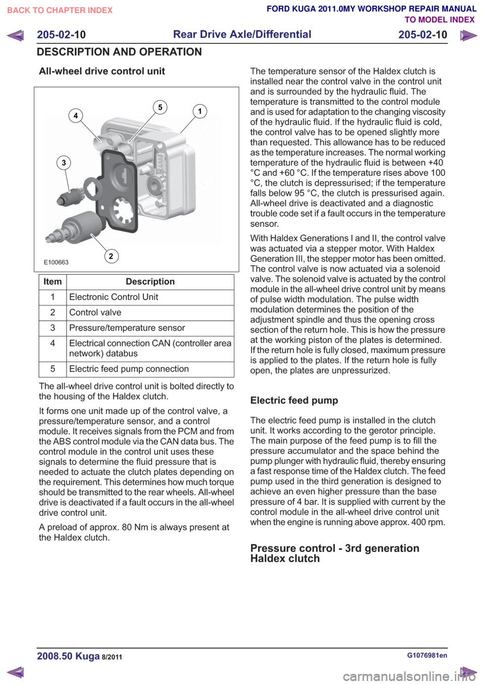
All-wheel drive control unit
E100663
14
3
2
5
Description
Item
Electronic Control Unit
1
Control valve
2
Pressure/temperature sensor
3
Electrical connection CAN (controller area
network) databus
4
Electric feed pump connection
5
The all-wheel drive control unit is bolted directly to
the housing of the Haldex clutch.
It forms one unit made up of the control valve, a
pressure/temperature sensor, and a control
module. It receives signals from the PCM and from
the ABS control module via the CAN data bus. The
control module in the control unit uses these
signals to determine the fluid pressure that is
needed to actuate the clutch plates depending on
the requirement. This determines how much torque
should be transmitted to the rear wheels. All-wheel
drive is deactivated if a fault occurs in the all-wheel
drive control unit.
A preload of approx. 80 Nm is always present at
the Haldex clutch. The temperature sensor of the Haldex clutch is
installed near the control valve in the control unit
and is surrounded by the hydraulic fluid. The
temperature is transmitted to the control module
and is used for adaptation to the changing viscosity
of the hydraulic fluid. If the hydraulic fluid is cold,
the control valve has to be opened slightly more
than requested. This allowance has to be reduced
as the temperature increases. The normal working
temperature of the hydraulic fluid is between +40
°C and +60 °C. If the temperature rises above 100
°C, the clutch is depressurised; if the temperature
falls below 95 °C, the clutch is pressurised again.
All-wheel drive is deactivated and a diagnostic
trouble code set if a fault occurs in the temperature
sensor.
With Haldex Generations I and II, the control valve
was actuated via a stepper motor. With Haldex
Generation III, the stepper motor has been omitted.
The control valve is now actuated via a solenoid
valve. The solenoid valve is actuated by the control
module in the all-wheel drive control unit by means
of pulse width modulation. The pulse width
modulation determines the position of the
adjustment spindle and thus the opening cross
section of the return hole. This is how the pressure
at the working piston of the plates is determined.
If the return hole is fully closed, maximum pressure
is applied to the plates. If the return hole is fully
open, the plates are unpressurized.
Electric feed pump
The electric feed pump is installed in the clutch
unit. It works according to the gerotor principle.
The main purpose of the feed pump is to fill the
pressure accumulator and the space behind the
pump plunger with hydraulic fluid, thereby ensuring
a fast response time of the Haldex clutch. The feed
pump used in the third generation is designed to
achieve an even higher pressure than the base
pressure of 4 bar. It is supplied with current by the
control module in the all-wheel drive control unit
when the engine is running above approx. 400 rpm.
Pressure control - 3rd generation
Haldex clutch
G1076981en2008.50 Kuga8/2011
205-02-
10
Rear Drive Axle/Differential
205-02- 10
DESCRIPTION AND OPERATION
TO MODEL INDEX
BACK TO CHAPTER INDEX
FORD KUGA 2011.0MY WORKSHOP REPAIR MANUAL
Page 1418 of 2057
Anti-Lock Control
schematic
and connector information.
General Equipment
The Ford approved diagnostic tool
Inspection and Verification
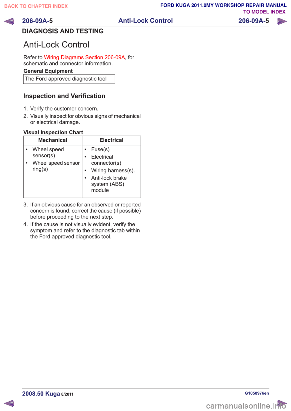
1. Verify the customer concern.
2. Visually inspect for obvious signs of mechanical or electrical damage.
Visual Inspection Chart
Electrical
Mechanical
• Fuse(s)
• Electricalconnector(s)
• Wiring harness(s).
• Anti-lock brake system (ABS)
module
• Wheel speed
sensor(s)
• Wheel speed sensor ring(s)
3. If an obvious cause for an observed or reported concern is found, correct the cause (if possible)
before proceeding to the next step.
4. If the cause is not visually evident, verify the symptom and refer to the diagnostic tab within
the Ford approved diagnostic tool.
G1058976en2008.50 Kuga8/2011
206-09A- 5
Anti-Lock Control
206-09A- 5
DIAGNOSIS AND TESTING
TO MODEL INDEX
BACK TO CHAPTER INDEX
FORD KUGA 2011.0MY WORKSHOP REPAIR MANUAL
Refer to
Wiring Diagrams Section 206-09A, for
Page 1419 of 2057
SECTION 206-09B Anti-Lock Control - Stability Assist
VEHICLE APPLICATION:2008.50 Kuga
PA G E
CONTENTS
DESCRIPTION AND OPERATION
206-09B-2
Anti-Lock Control - Stability Assist (Component Location) .................................................
206-09B-3
Anti-Lock Control - Stability Assist (Overview) ...................................................................
206-09B-3
Overview ........................................................................\
.....................................................
206-09B-4
Testing the brakes on a roller dynamometer - 4X4 vehicles only ...................................
206-09B-4
ABS/ESP module or hydraulic control unit (HCU) ..............................................................
206-09B-4
Combined yaw rate sensor and lateral acceleration sensor / longitudinal acceleration
sensor ........................................................................\
.......................................................
206-09B-5
Front wheel sensor ........................................................................\
.....................................
206-09B-5
Rear wheel sensor ........................................................................\
......................................
206-09B-5
Opto-electronic steering wheel rotation sensor ..................................................................
206-09B-6
ESP switch ........................................................................\
.................................................
206-09B-7
Anti-Lock Control - Stability Assist (System Operation and Component Description) ........
206-09B-7
System Diagram ........................................................................\
.........................................
206-09B-8
System Operation ........................................................................\
.......................................
206-09B-9
PRINCIPLES OF OPERATION ........................................................................\
...............
206-09B-11
Component Description ........................................................................\
..............................
206-09B-?
Opto-electronic steering wheel rotation sensor ..............................................................
206-09B-?
ABS/ESP module or hydraulic control unit (HCU) ..........................................................
206-09B-?
ESP switch ........................................................................\
..............................................
206-09B-?
Combined yaw rate sensor and lateral acceleration sensor / longitudinal acceleration
sensor........................................................................\
................................................... 206-09B-?
Front wheel sensor ........................................................................\
.................................
206-09B-?
Rear wheel sensor ........................................................................\
..................................
REMOVAL AND INSTALLATION 206-09B-16
Hydraulic Control Unit (HCU) ........................................................................\
.....................
206-09B-19
Stability Assist Module ........................................................................\
................................
206-09B-21
Front Wheel Speed Sensor ........................................................................\
........................
206-09B-22
Rear Wheel Speed Sensor ........................................................................\
.........................
206-09B-23
Yaw Rate Sensor ........................................................................\
........................................
206-09B-1
Anti-Lock Control - Stability Assist
206-09B- 1
.
TO MODEL INDEX
BACK TO CHAPTER INDEX
FORD KUGA 2011.0MY WORKSHOP REPAIR MANUAL
Page 1421 of 2057
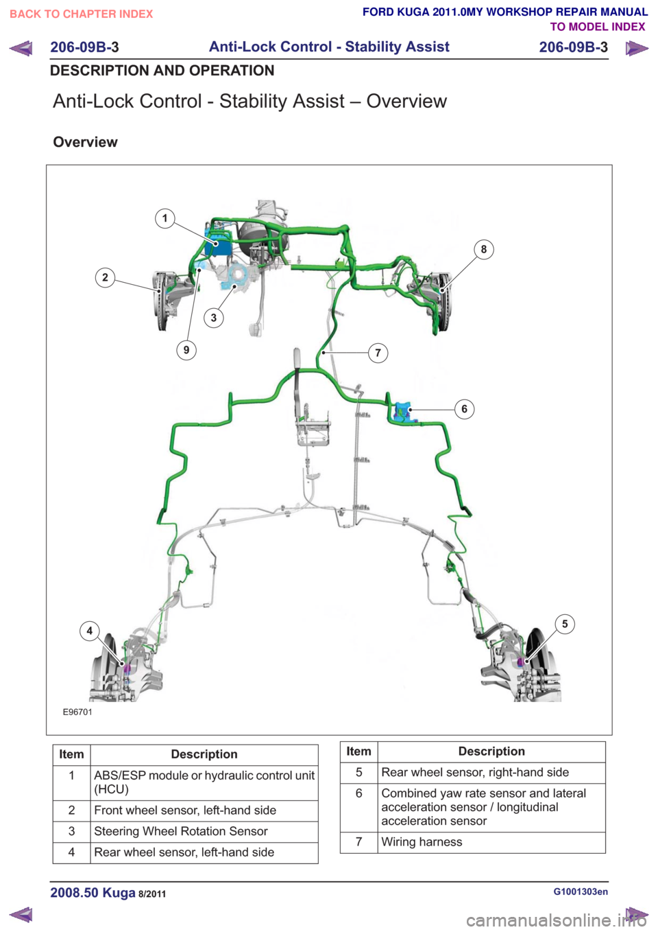
Anti-Lock Control - Stability Assist – Overview
Overview
E96701
1
2
3
45
6
7
8
9
Description
Item
ABS/ESP module or hydraulic control unit
(HCU)
1
Front wheel sensor, left-hand side
2
Steering Wheel Rotation Sensor
3
Rear wheel sensor, left-hand side
4Description
Item
Rear wheel sensor, right-hand side
5
Combined yaw rate sensor and lateral
acceleration sensor / longitudinal
acceleration sensor
6
Wiring harness
7
G1001303en2008.50 Kuga8/2011
206-09B- 3
Anti-Lock Control - Stability Assist
206-09B- 3
DESCRIPTION AND OPERATION
TO MODEL INDEX
BACK TO CHAPTER INDEX
FORD KUGA 2011.0MY WORKSHOP REPAIR MANUAL
Page 1422 of 2057
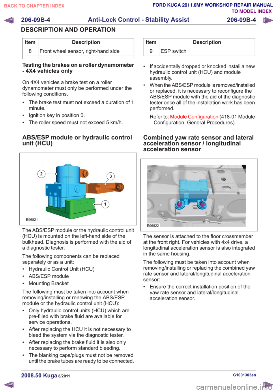
Description
Item
Front wheel sensor, right-hand side
8Description
Item
9 ESP switch
Testing the brakes on a roller dynamometer
- 4X4 vehicles only
On 4X4 vehicles a brake test on a roller
dynamometer must only be performed under the
following conditions.
• The brake test must not exceed a duration of 1 minute.
• Ignition key in position 0.
• The roller speed must not exceed 5 km/h.
ABS/ESP module or hydraulic control
unit (HCU)
E96821
1
23
The ABS/ESP module or the hydraulic control unit
(HCU) is mounted on the left-hand side of the
bulkhead. Diagnosis is performed with the aid of
a diagnostic tester.
The following components can be replaced
separately or as a unit:
• Hydraulic Control Unit (HCU)
• ABS/ESP module
• Mounting Bracket
The following must be taken into account when
removing/installing or renewing the ABS/ESP
module or the hydraulic control unit (HCU):
• Only hydraulic control units (HCU) which are pre-filled with brake fluid are available for
service operations.
• After replacing the HCU it is not necessary to bleed the system via the diagnostic tester.
• After replacing the brake fluid it is also only necessary to perform standard bleeding.
• The blanking caps/plugs must not be removed until the brake tubes are ready to be connected. • If accidentally dropped or knocked install a new
hydraulic control unit (HCU) and module
assembly.
• When the ABS/ESP module is removed/installed or replaced, it is necessary to reconfigure the
ABS/ESP module with the aid of the diagnostic
tester once all of the installation work has been
performed.
Refer to: Module Configuration (418-01 Module
Configuration, General Procedures).
Combined yaw rate sensor and lateral
acceleration sensor / longitudinal
acceleration sensor
E96822
The sensor is attached to the floor crossmember
at the front right. For vehicles with 4x4 drive, a
longitudinal acceleration sensor is also integrated
in the same housing.
The following must be taken into account when
removing/installing or replacing the combined yaw
rate sensor and lateral/longitudinal acceleration
sensor:
• Ensure the correct installation position of the yaw rate sensor and lateral/longitudinal
acceleration sensor.
G1001303en2008.50 Kuga8/2011
206-09B- 4
Anti-Lock Control - Stability Assist
206-09B- 4
DESCRIPTION AND OPERATION
TO MODEL INDEX
BACK TO CHAPTER INDEX
FORD KUGA 2011.0MY WORKSHOP REPAIR MANUAL
Page 1423 of 2057
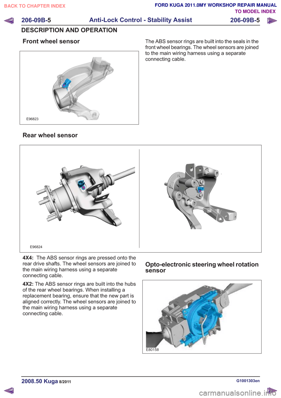
Front wheel sensor
E96823
The ABS sensor rings are built into the seals in the
front wheel bearings. The wheel sensors are joined
to the main wiring harness using a separate
connecting cable.
Rear wheel sensor
E96824
4X4:The ABS sensor rings are pressed onto the
rear drive shafts. The wheel sensors are joined to
the main wiring harness using a separate
connecting cable.
4X2: The ABS sensor rings are built into the hubs
of the rear wheel bearings. When installing a
replacement bearing, ensure that the new part is
aligned correctly. The wheel sensors are joined to
the main wiring harness using a separate
connecting cable.
Opto-electronic steering wheel rotation
sensor
E80158
G1001303en2008.50 Kuga8/2011
206-09B- 5
Anti-Lock Control - Stability Assist
206-09B- 5
DESCRIPTION AND OPERATION
TO MODEL INDEX
BACK TO CHAPTER INDEX
FORD KUGA 2011.0MY WORKSHOP REPAIR MANUAL
Page 1426 of 2057
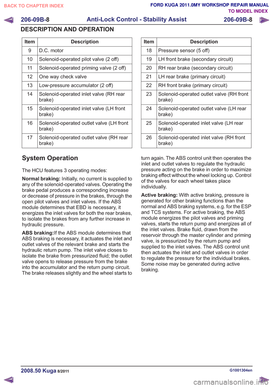
Description
Item
D.C. motor
9
Solenoid-operated pilot valve (2 off)
10
Solenoid-operated priming valve (2 off)
11
One way check valve
12
Low-pressure accumulator (2 off)
13
Solenoid-operated inlet valve (RH rear
brake)
14
Solenoid-operated inlet valve (LH front
brake)
15
Solenoid-operated outlet valve (LH front
brake)
16
Solenoid-operated outlet valve (RH rear
brake)
17Description
Item
Pressure sensor (5 off)
18
LH front brake (secondary circuit)
19
RH rear brake (secondary circuit)
20
LH rear brake (primary circuit)
21
RH front brake (primary circuit)
22
Solenoid-operated outlet valve (RH front
brake)
23
Solenoid-operated outlet valve (LH rear
brake)
24
Solenoid-operated inlet valve (LH rear
brake)
25
Solenoid-operated inlet valve (RH front
brake)
26
System Operation
The HCU features 3 operating modes:
Normal braking:
Initially, no current is supplied to
any of the solenoid-operated valves. Operating the
brake pedal produces a corresponding increase
or decrease of pressure in the brakes, through the
open pilot valves and inlet valves. If the ABS
module determines that EBD is necessary, it
energizes the inlet valves for both the rear brakes,
to isolate the brakes from any further increase in
hydraulic pressure.
ABS braking: If the ABS module determines that
ABS braking is necessary, it actuates the inlet and
outlet valves of the relevant brake and starts the
hydraulic return pump. The inlet valve closes to
isolate the brake from pressurized fluid; the outlet
valve opens to release pressure from the brake
into the accumulator and the return pump circuit.
The brake releases slightly and the wheel starts to turn again. The ABS control unit then operates the
inlet and outlet valves to regulate the hydraulic
pressure acting on the brake in order to maximize
braking effect without the wheel locking up. Control
of the valves for each wheel takes place
individually.
Active braking:
With active braking, pressure is
generated for other braking functions than the
normal and ABS braking systems, e.g. for the ESP
and TCS systems. For active braking, the ABS
module energizes the pilot valves and priming
valves, starts the return pump and energizes all of
the inlet valves. Brake fluid, drawn from the
reservoir through the master cylinder and priming
valve, is pressurized by the return pump and
supplied to the inlet valves. The ABS control unit
then actuates the inlet and outlet valves in order
to regulate the pressure for the individual brakes.
Some noise may be generated during active
braking.
G1001304en2008.50 Kuga8/2011
206-09B- 8
Anti-Lock Control - Stability Assist
206-09B- 8
DESCRIPTION AND OPERATION
TO MODEL INDEX
BACK TO CHAPTER INDEX
FORD KUGA 2011.0MY WORKSHOP REPAIR MANUAL