Page 1869 of 2057
5252
E125820
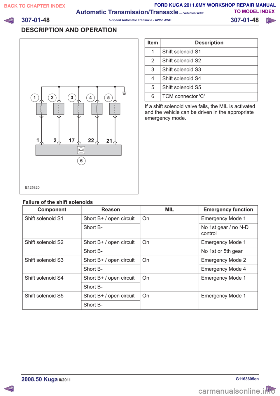
12345
6
Description
Item
Shift solenoid S1
1
Shift solenoid S2
2
Shift solenoid S3
3
Shift solenoid S4
4
Shift solenoid S5
5
TCM connector 'C'
6
If a shift solenoid valve fails, the MIL is activated
and the vehicle can be driven in the appropriate
emergency mode.
Failure of the shift solenoids
Emergency function
MIL
Reason
Component
Emergency Mode 1
On
Short B+ / open circuit
Shift solenoid S1
No 1st gear / no N-D
control
Short B-
Emergency Mode 1
On
Short B+ / open circuit
Shift solenoid S2
No 1st or 5th gear
Short B-
Emergency Mode 2
On
Short B+ / open circuit
Shift solenoid S3
Emergency Mode 4
Short B-
Emergency Mode 1
On
Short B+ / open circuit
Shift solenoid S4
Short B- Emergency Mode 1
On
Short B+ / open circuit
Shift solenoid S5
Short B-
G1163605en2008.50 Kuga8/2011
307-01-48
Automatic Transmission/Transaxle
— Vehicles With:
5-Speed Automatic Transaxle - AW55 AWD
307-01- 48
DESCRIPTION AND OPERATION
TO MODEL INDEX
BACK TO CHAPTER INDEX
FORD KUGA 2011.0MY WORKSHOP REPAIR MANUAL
Page 1870 of 2057
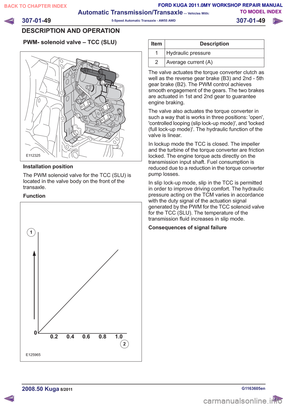
PWM- solenoid valve – TCC (SLU)
E112325
Installation position
The PWM solenoid valve for the TCC (SLU) is
located in the valve body on the front of the
transaxle.
Function
00.2 1.0 0.80.60.4
0
0.2 1.0
0.80.60.4
0
0.2 1.0
0.80.60.40
0.2 1.0 0.80.60.4
E125965
1
2
Description
Item
Hydraulic pressure
1
Average current (A)
2
The valve actuates the torque converter clutch as
well as the reverse gear brake (B3) and 2nd - 5th
gear brake (B2). The PWM control achieves
smooth engagement of the gears. The two brakes
are actuated in 1st and 2nd gear to guarantee
engine braking.
The valve also actuates the torque converter in
such a way that is works in three positions: 'open',
'controlled looping (slip lock-up mode)', and 'locked
(full lock-up mode)'. The hydraulic function of the
valve is linear.
In lockup mode the TCC is closed. The impeller
and the turbine of the torque converter are friction
locked. The engine torque acts directly on the
transmission input shaft. Fuel consumption is
reduced due to a reduction in the torque converter
pump losses.
In slip lock-up mode, slip in the TCC is permitted
in order to improve driving comfort. The hydraulic
pressure acting on the TCM varies in accordance
with the duty signal of the actuation signal
generated by the PWM for the TCC solenoid valve
for the TCC (SLU). The temperature of the
transmission fluid increases in slip mode.
Consequences of signal failure
G1163605en2008.50 Kuga8/2011
307-01- 49
Automatic Transmission/Transaxle
— Vehicles With:
5-Speed Automatic Transaxle - AW55 AWD
307-01- 49
DESCRIPTION AND OPERATION
TO MODEL INDEX
BACK TO CHAPTER INDEX
FORD KUGA 2011.0MY WORKSHOP REPAIR MANUAL
Page 1871 of 2057
E125966
97
2
1
Description
Item
PWM- solenoid valve – TCC (SLU)
1
TCM connector 'C'
2
If the PWM solenoid valve for the TCC (SLU) fails,
the MIL is activated and the vehicle can be driven
in emergency mode 1.
PWM solenoid valve – shift pressure (SLS)
E112326
Installation position
The PWM solenoid valve for shift pressure (SLS)
is located in the valve body on the front of the
transaxle.
Function
0 0.2 1.00.80.60.4
0
0.2 1.00.80.60.4
0
0.2 1.00.80.60.40
0.2 1.00.80.60.4
E125990
1
2
G1163605en2008.50 Kuga8/2011
307-01- 50
Automatic Transmission/Transaxle
— Vehicles With:
5-Speed Automatic Transaxle - AW55 AWD
307-01- 50
DESCRIPTION AND OPERATION
TO MODEL INDEX
BACK TO CHAPTER INDEX
FORD KUGA 2011.0MY WORKSHOP REPAIR MANUAL
Page 1872 of 2057
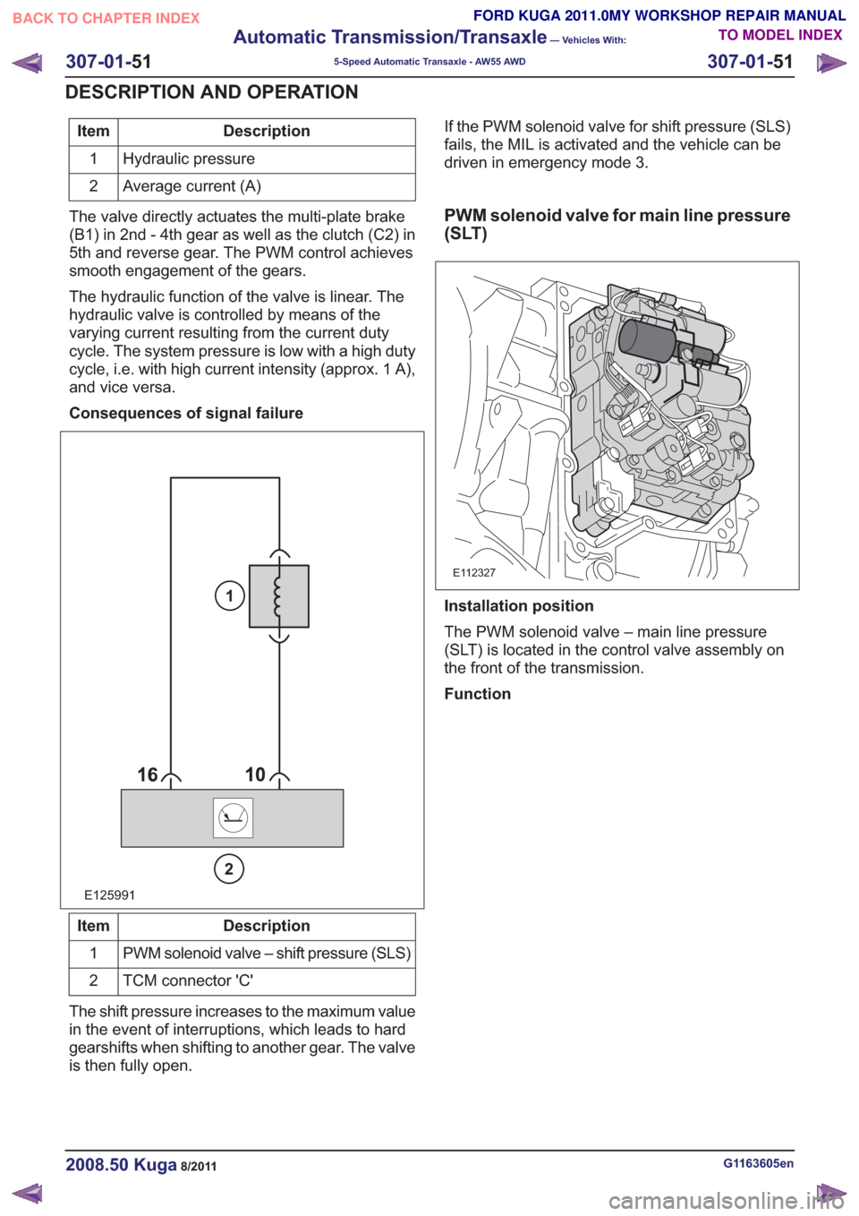
Description
Item
Hydraulic pressure
1
Average current (A)
2
The valve directly actuates the multi-plate brake
(B1) in 2nd - 4th gear as well as the clutch (C2) in
5th and reverse gear. The PWM control achieves
smooth engagement of the gears.
The hydraulic function of the valve is linear. The
hydraulic valve is controlled by means of the
varying current resulting from the current duty
cycle. The system pressure is low with a high duty
cycle, i.e. with high current intensity (approx. 1 A),
and vice versa.
Consequences of signal failure
E125991
2
1
Description
Item
PWM solenoid valve – shift pressure (SLS)
1
TCM connector 'C'
2
The shift pressure increases to the maximum value
in the event of interruptions, which leads to hard
gearshifts when shifting to another gear. The valve
is then fully open. If the PWM solenoid valve for shift pressure (SLS)
fails, the MIL is activated and the vehicle can be
driven in emergency mode 3.
PWM solenoid valve for main line pressure
(SLT)
E112327
Installation position
The PWM solenoid valve – main line pressure
(SLT) is located in the control valve assembly on
the front of the transmission.
Function
G1163605en2008.50 Kuga8/2011
307-01-
51
Automatic Transmission/Transaxle
— Vehicles With:
5-Speed Automatic Transaxle - AW55 AWD
307-01- 51
DESCRIPTION AND OPERATION
TO MODEL INDEX
BACK TO CHAPTER INDEX
FORD KUGA 2011.0MY WORKSHOP REPAIR MANUAL
Page 1873 of 2057
00.2 1.0 0.80.60.4
0
0.2 1.0
0.80.60.40
0.2 1.0 0.80.60.40
0.2 1.0 0.80.60.4
E125990
1
2
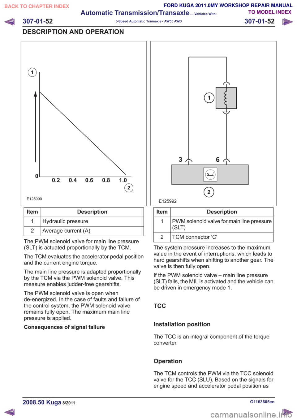
Description
Item
Hydraulic pressure
1
Average current (A)
2
The PWM solenoid valve for main line pressure
(SLT) is actuated proportionally by the TCM.
The TCM evaluates the accelerator pedal position
and the current engine torque.
The main line pressure is adapted proportionally
by the TCM via the PWM solenoid valve. This
measure enables judder-free gearshifts.
The PWM solenoid valve is open when
de-energized. In the case of faults and failure of
the control system, the PWM solenoid valve
remains fully open. The maximum main line
pressure is applied.
Consequences of signal failure
E125992
2
1
Description
Item
PWM solenoid valve for main line pressure
(SLT)
1
TCM connector 'C'
2
The system pressure increases to the maximum
value in the event of interruptions, which leads to
hard gearshifts when shifting to another gear. The
valve is then fully open.
If the PWM solenoid valve – main line pressure
(SLT) fails, the MIL is activated and the vehicle can
be driven in emergency mode 1.
TCC
Installation position
The TCC is an integral component of the torque
converter.
Operation
The TCM controls the PWM via the TCC solenoid
valve for the TCC (SLU). Based on the signals for
engine speed and accelerator pedal position as
G1163605en2008.50 Kuga8/2011
307-01- 52
Automatic Transmission/Transaxle
— Vehicles With:
5-Speed Automatic Transaxle - AW55 AWD
307-01- 52
DESCRIPTION AND OPERATION
TO MODEL INDEX
BACK TO CHAPTER INDEX
FORD KUGA 2011.0MY WORKSHOP REPAIR MANUAL
Page 1874 of 2057
well as vehicle speed, driving comfort is improved
by linear actuation of the TCC.
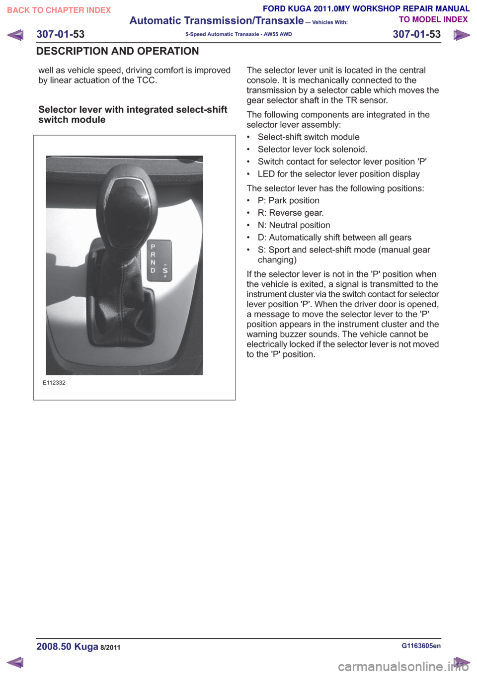
Selector lever with integrated select-shift
switch module
E112332
The selector lever unit is located in the central
console. It is mechanically connected to the
transmission by a selector cable which moves the
gear selector shaft in the TR sensor.
The following components are integrated in the
selector lever assembly:
• Select-shift switch module
• Selector lever lock solenoid.
• Switch contact for selector lever position 'P'
• LED for the selector lever position display
The selector lever has the following positions:
• P: Park position
• R: Reverse gear.
• N: Neutral position
• D: Automatically shift between all gears
• S: Sport and select-shift mode (manual gearchanging)
If the selector lever is not in the 'P' position when
the vehicle is exited, a signal is transmitted to the
instrument cluster via the switch contact for selector
lever position 'P'. When the driver door is opened,
a message to move the selector lever to the 'P'
position appears in the instrument cluster and the
warning buzzer sounds. The vehicle cannot be
electrically locked if the selector lever is not moved
to the 'P' position.
G1163605en2008.50 Kuga8/2011
307-01- 53
Automatic Transmission/Transaxle
— Vehicles With:
5-Speed Automatic Transaxle - AW55 AWD
307-01- 53
DESCRIPTION AND OPERATION
TO MODEL INDEX
BACK TO CHAPTER INDEX
FORD KUGA 2011.0MY WORKSHOP REPAIR MANUAL
Page 1875 of 2057

Overview of the select-shift switch module
E112331
The select-shift switch module is located on the
upper trim of the selector lever unit. The module
is supplied with power by the TCM.
It uses the LIN databus to interact with the TCM,
for instance to activate the selector lever position
display.
It allows the automatic transmission gears to be
changed up and down manually via the signals of
the Hall sensors.
The select-shift switch module detects the selector
lever position 'P' and 'S' via the integrated selector
lever position sensors (Hall sensors).
A cable leading from the TCM passes directly to
the select-shift switch module and is used to control
the solenoid of the selector lever lock. The
switching solenoid receives its voltage supply
directly from the module.
In the event of a fault, a signal is transmitted to the
TCM where all DTCs are stored.
Oil pump
E68097
1
2
3
45
Description
Item
Fluid pump rotor, outer
1
Fluid pump rotor, inner
2
G1163605en2008.50 Kuga8/2011
307-01- 54
Automatic Transmission/Transaxle
— Vehicles With:
5-Speed Automatic Transaxle - AW55 AWD
307-01- 54
DESCRIPTION AND OPERATION
TO MODEL INDEX
BACK TO CHAPTER INDEX
FORD KUGA 2011.0MY WORKSHOP REPAIR MANUAL
Page 1876 of 2057
Description
Item
Drive
3
Intake side
4
Delivery side
5
The fluid pump operates on the principle of a
G-rotor fluid pump.
The fluid pump draws transmission fluid from the
fluid pan, builds up fluid pressure and then supplies
it to the valve body.
The fluid pump is driven by the crankshaft via the
torque converter housing.
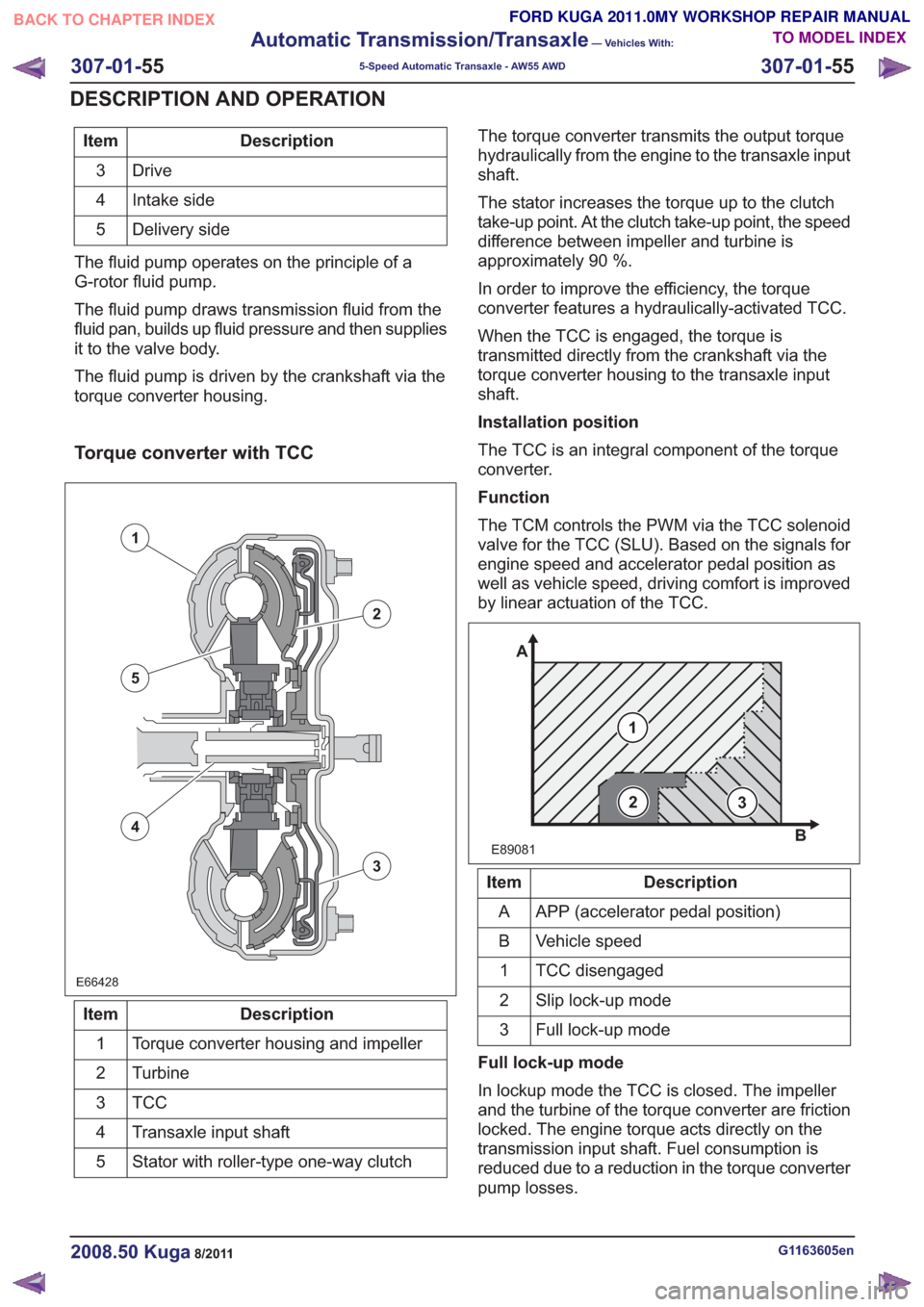
Torque converter with TCC
E66428E66428
1
2
3
5
4
Description
Item
Torque converter housing and impeller
1
Turbine
2
TCC3
Transaxle input shaft
4
Stator with roller-type one-way clutch
5 The torque converter transmits the output torque
hydraulically from the engine to the transaxle input
shaft.
The stator increases the torque up to the clutch
take-up point. At the clutch take-up point, the speed
difference between impeller and turbine is
approximately 90 %.
In order to improve the efficiency, the torque
converter features a hydraulically-activated TCC.
When the TCC is engaged, the torque is
transmitted directly from the crankshaft via the
torque converter housing to the transaxle input
shaft.
Installation position
The TCC is an integral component of the torque
converter.
Function
The TCM controls the PWM via the TCC solenoid
valve for the TCC (SLU). Based on the signals for
engine speed and accelerator pedal position as
well as vehicle speed, driving comfort is improved
by linear actuation of the TCC.
E89081
1
A
B
23
Description
Item
APP (accelerator pedal position)
A
Vehicle speed
B
TCC disengaged
1
Slip lock-up mode
2
Full lock-up mode
3
Full lock-up mode
In lockup mode the TCC is closed. The impeller
and the turbine of the torque converter are friction
locked. The engine torque acts directly on the
transmission input shaft. Fuel consumption is
reduced due to a reduction in the torque converter
pump losses.
G1163605en2008.50 Kuga8/2011
307-01- 55
Automatic Transmission/Transaxle
— Vehicles With:
5-Speed Automatic Transaxle - AW55 AWD
307-01- 55
DESCRIPTION AND OPERATION
TO MODEL INDEX
BACK TO CHAPTER INDEX
FORD KUGA 2011.0MY WORKSHOP REPAIR MANUAL