Page 228 of 2057

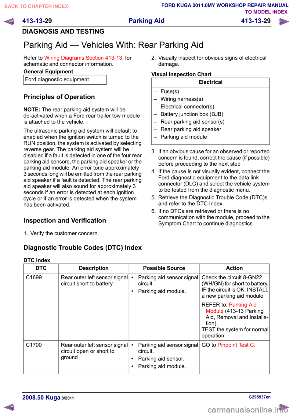
Parking Aid — Vehicles With: Rear Parking Aid
Refer to
Wiring Diagrams Section 413-13, for
schematic and connector information. General Equipment
Ford diagnostic equipment
Principles of Operation
NOTE: The rear parking aid system will be
de-activated when a Ford rear trailer tow module
is attached to the vehicle.
The ultrasonic parking aid system will default to
enabled when the ignition switch is turned to the
RUN position, the system is activated by selecting
reverse gear. The parking aid system will be
disabled if a fault is detected in one of the four rear
parking aid sensors, the parking aid speaker or the
parking aid module. An error tone approximately
3 seconds long will be emitted from the rear parking
aid speaker if a fault is detected. The rear parking
aid speaker will also sound for approximately 3
seconds if an error is detected at each ignition
cycle or if an error is detected when the system
has been activated.
Inspection and Verification
1. Verify the customer concern. 2. Visually inspect for obvious signs of electrical
damage.
Visual Inspection Chart Electrical
– Fuse(s)
– Wiring harness(s)
– Electrical connector(s)
– Battery junction box (BJB)
– Rear parking aid sensor(s)
– Rear parking aid speaker
– Parking aid module
3. If an obvious cause for an observed or reported concern is found, correct the cause (if possible)
before proceeding to the next step
4. If the cause is not visually evident, connect the Ford diagnostic equipment to the data link
connector (DLC) and select the vehicle system
to be tested from the diagnostic menu.
5. Retrieve the Diagnostic Trouble Code (DTC)s and refer to the DTC Index.
6. If no DTCs are retrieved or there is no communication with the module, proceed to the
Symptom Chart to continue diagnostics.
Diagnostic Trouble Codes (DTC) Index
DTC Index Action
Possible Source
Description
DTC
Check the circuit 8-GN22
(WH/GN) for short to battery.
IF the circuit is OK, INSTALL
a new parking aid module.
REFER to:Parking Aid
Module (413-13 Parking
Aid, Removal and Installa-
tion).
TEST the system for normal
operation.
• Parking aid sensor signal
circuit.
• Parking aid module.
Rear outer left sensor signal
circuit short to battery
C1699
GO toPinpoint Test C.
• Parking aid sensor signal
circuit.
• Parking aid sensor.
• Parking aid module.
Rear outer left sensor signal
circuit open or short to
ground
C1700 G295937en
2008.50 Kuga 8/2011 413-13-29
Parking Aid
413-13-29
DIAGNOSIS AND TESTINGTO MODEL INDEX
BACK TO CHAPTER INDEX
FORD KUGA 2011.0MY WORKSHOP REPAIR MANUAL
Page 245 of 2057
Parking Aid Camera
General Equipment
4 mm Drill Bit General Equipment
Blind Rivet Gun
Electric Drill
Removal
1. General Equipment: Electric Drill
General Equipment: 4 mm Drill Bit Installation
1.
General Equipment: Blind Rivet Gun G1065989en
2008.50 Kuga 8/2011 413-13-46
Parking Aid
413-13-46
REMOVAL AND INSTALLATIONTO MODEL INDEX
BACK TO CHAPTER INDEX
FORD KUGA 2011.0MY WORKSHOP REPAIR MANUALE116041
Page 249 of 2057
Front Parking Aid Sensor
Special Tool(s) / General Equipment
501-135
Punching Tool, Parking Aid
Sensor Special Tool(s) / General Equipment
12 mm Drill Bit
Electric Drill
Flat File
Removal
1. 2.
G1186709en
2008.50 Kuga 8/2011 413-13-50
Parking Aid
413-13-50
REMOVAL AND INSTALLATIONTO MODEL INDEX
BACK TO CHAPTER INDEX
FORD KUGA 2011.0MY WORKSHOP REPAIR MANUALE92959 E115725x16
Page 255 of 2057
Rear Parking Aid Sensor
Special Tool(s) / General Equipment
501-135
Punching Tool, Parking Aid
Sensor Special Tool(s) / General Equipment
501-160
Punching Tool, Parking Aid
Sensor 12 mm Drill Bit
Electric Drill
Flat File
Removal
1. Refer to: Rear Bumper Cover (501-19 Bumpers,
Removal and Installation).
2. 3.
G1186710en
2008.50 Kuga 8/2011 413-13-56
Parking Aid
413-13-56
REMOVAL AND INSTALLATIONTO MODEL INDEX
BACK TO CHAPTER INDEX
FORD KUGA 2011.0MY WORKSHOP REPAIR MANUALE92959 E116749 E115590x4x5
Page 256 of 2057
Installation
1. NOTE:
Cutlines may already exist on the inner
surface of a new bumper cover.
General Equipment: Electric Drill
General Equipment: 12 mm Drill Bit G1186710en
2008.50 Kuga 8/2011 413-13-57
Parking Aid
413-13-57
REMOVAL AND INSTALLATIONTO MODEL INDEX
BACK TO CHAPTER INDEX
FORD KUGA 2011.0MY WORKSHOP REPAIR MANUALE115589x3x2x2x3x3x2
Page 262 of 2057
SECTION 414-00 Charging System - General
Information
VEHICLE APPLICATION:
2008.50 Kuga
PAGE
CONTENTS
DIAGNOSIS AND TESTING
414-00-2
Charging System................................................................................................................
414-00-2
Inspection and Verification..................................................................................................
414-00-2
Component Tests................................................................................................................ 414-00-1
Charging System - General Information
414-00-1
.TO MODEL INDEX
BACK TO CHAPTER INDEX
FORD KUGA 2011.0MY WORKSHOP REPAIR MANUAL
Page 263 of 2057

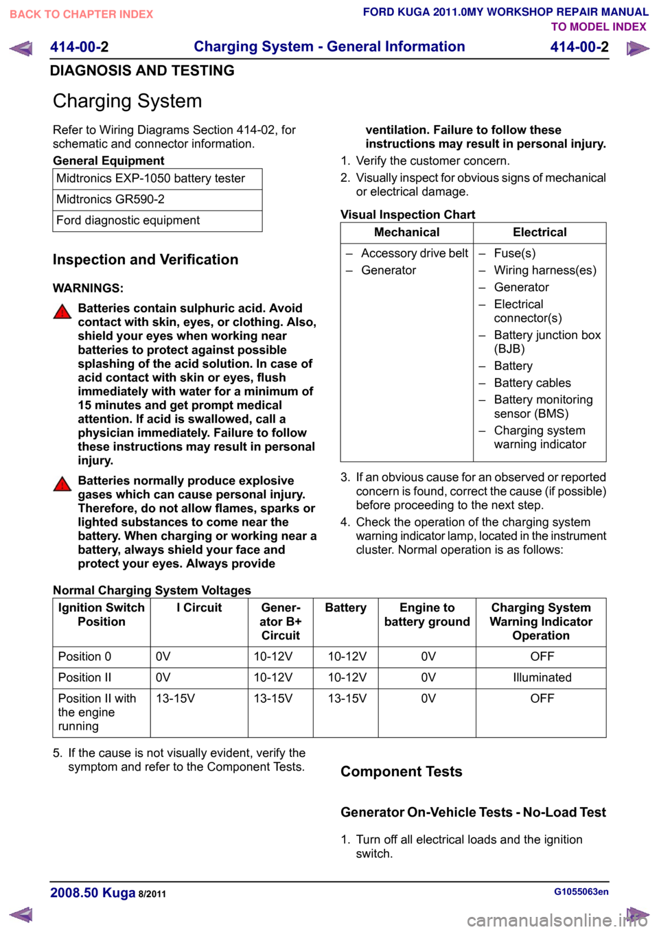
Charging System
Refer to Wiring Diagrams Section 414-02, for
schematic and connector information.
General Equipment
Midtronics EXP-1050 battery tester
Midtronics GR590-2
Ford diagnostic equipment
Inspection and Verification
WARNINGS: Batteries contain sulphuric acid. Avoid
contact with skin, eyes, or clothing. Also,
shield your eyes when working near
batteries to protect against possible
splashing of the acid solution. In case of
acid contact with skin or eyes, flush
immediately with water for a minimum of
15 minutes and get prompt medical
attention. If acid is swallowed, call a
physician immediately. Failure to follow
these instructions may result in personal
injury.
Batteries normally produce explosive
gases which can cause personal injury.
Therefore, do not allow flames, sparks or
lighted substances to come near the
battery. When charging or working near a
battery, always shield your face and
protect your eyes. Always provide
ventilation. Failure to follow these
instructions may result in personal injury.
1. Verify the customer concern.
2. Visually inspect for obvious signs of mechanical
or electrical damage.
Visual Inspection Chart Electrical
Mechanical
– Fuse(s)
– Wiring harness(es)
– Generator
– Electricalconnector(s)
– Battery junction box (BJB)
– Battery
– Battery cables
– Battery monitoring sensor (BMS)
– Charging system warning indicator
–
Accessory drive belt
– Generator
3. If an obvious cause for an observed or reported concern is found, correct the cause (if possible)
before proceeding to the next step.
4. Check the operation of the charging system warning indicator lamp, located in the instrument
cluster. Normal operation is as follows:
Normal Charging System Voltages Charging System
Warning Indicator Operation
Engine to
battery ground
Battery
Gener-
ator B+ Circuit
I Circuit
Ignition Switch
Position
OFF
0V
10-12V
10-12V
0V
Position 0
Illuminated
0V
10-12V
10-12V
0V
Position II
OFF
0V
13-15V
13-15V
13-15V
Position II with
the engine
running
5. If the cause is not visually evident, verify the symptom and refer to the Component Tests. Component Tests
Generator On-Vehicle Tests - No-Load Test
1. Turn off all electrical loads and the ignition
switch. G1055063en
2008.50 Kuga 8/2011 414-00-2
Charging System - General Information
414-00-2
DIAGNOSIS AND TESTINGTO MODEL INDEX
BACK TO CHAPTER INDEX
FORD KUGA 2011.0MY WORKSHOP REPAIR MANUAL
Page 264 of 2057

2. Switch the multimeter to the voltage function.
3. Connect the leads of the multimeter across the
battery terminals.
4. Read the voltage (base voltage).
5. Start the engine.
6. Run the engine at 1500 rpm with no electrical load.
7. Read the voltage. The voltage should be in the range of 14.1 volts to 15.1 volts. If the voltage
increase is less than 2.5 volts above the base
voltage, carry out the Load Test. If the voltage
increase is greater than 2.5 volts, REFER to the
Ford diagnostic equipment. Generator On-Vehicle Tests - Load Test
1. With the engine running, turn on the air
conditioning (if equipped), turn the blower motor
to high speed and the headlamps to high beam.
2. Increase the engine speed to 2000 rpm. The voltage should increase a minimum of 0.5 volts
above the base voltage. If the voltage does not
increase as specified, REFER to the Ford
approved diagnostic tool. If the voltage
increases as specified, the charging system is
charging correctly.
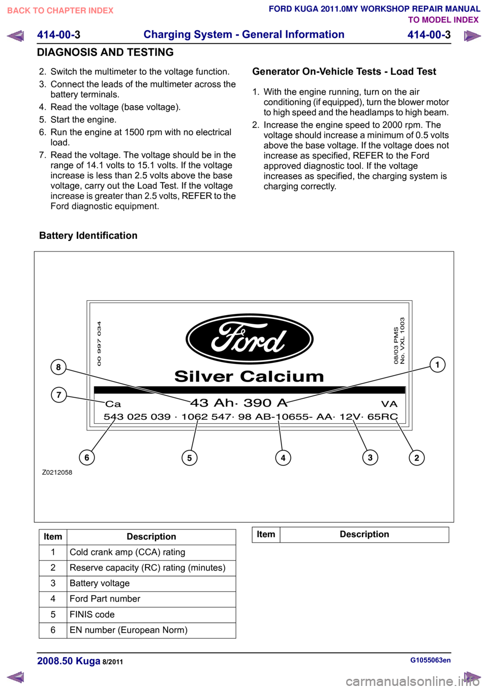
Battery Identification Description
Item
Cold crank amp (CCA) rating
1
Reserve capacity (RC) rating (minutes)
2
Battery voltage
3
Ford Part number
4
FINIS code
5
EN number (European Norm)
6 Description
Item G1055063en
2008.50 Kuga 8/2011 414-00-3
Charging System - General Information
414-00-3
DIAGNOSIS AND TESTINGTO MODEL INDEX
BACK TO CHAPTER INDEX
FORD KUGA 2011.0MY WORKSHOP REPAIR MANUALZ0212058