2011 FORD KUGA ASSEMBLY
[x] Cancel search: ASSEMBLYPage 1852 of 2057
The TCM detects uphill driving by comparing the
engine load transmitted by the PCM with the engine
speed. If the engine load increases and the engine
speed falls, then the TCM causes the transaxle to
shift to a lower transmission range in order to
increase the traction force.
Downhill driving
The TCM detects downhill driving by comparing
the engine load and engine speed values
transmitted by the PCM with the OSS sensor
signal. In order to prevent overloading of the
vehicle brakes, the TCM causes the transaxle to
shift to a lower transmission range.
Hill-hold function
If the vehicle is stopped on an uphill incline, the
TCM detects this through the faster drop in engine
speed compared with the drop in engine speed
when stopping on the flat. In this situation, the
hydraulics are actuated by the TCM in such a way
that the vehicle is prevented from rolling back. This
function is not used on steep inclines.
If the vehicle is parked on an uphill incline (ignition
switched off), the hill-hold function is not active
when pulling away.
Altitude correction
Lower air density results in reduced engine
performance. In order to compensate for this
operating situation, the TCM changes the shift
points.
Selector lever lock
To prevent the selector lever being accidentally
moved from the P or N position, the vehicle also
has an electrically operated selector lever lock.
This blocks the locking pin in the locking segment
and thus locks the selector lever in the P or N
position.
Shifting from P into another transmission
range
To be able to move the selector lever from P into
another transmission range, the ignition must be
switched on and the brake pedal must be
depressed (stop light switch on). The TCM detects
the position of the brake pedal via the CAN data
bus and the engaged transmission range from the
TR sensor.
The signal is then transferred from the TCM to the
select-shift switch module in order to activate the
solenoid valve in the selector mechanism
assembly.
In position P, the solenoid valve is activated and
the locking pin is pulled in so that the lock button
on the selector lever can be pressed as usual to
engage another transmission range.
In the selector mechanism assembly there is a Hall
sensor which is affected by a permanent magnet
on the gate of the selector mechanism assembly.
If the selector lever is moved from the P position,
both the Hall sensor and the selector lever lock
solenoid are simultaneously deactivated, to prevent
the selector from being kept in the N position.
If the ignition is set to "I" or "0" the solenoid valve
is deactivated. When the selector lever is in the P
position, it is mechanically locked because it has
no voltage.
Shifting from N into another transmission
range
The conditions are the same as for shifting from P
into another transmission range.
However, the lock button on the selector lever must
be pressed to be able to select R or P.
Power flow through the transmission
Clutches and brakes
G1163605en2008.50 Kuga8/2011
307-01-31
Automatic Transmission/Transaxle
— Vehicles With:
5-Speed Automatic Transaxle - AW55 AWD
307-01- 31
DESCRIPTION AND OPERATION
TO MODEL INDEX
BACK TO CHAPTER INDEX
FORD KUGA 2011.0MY WORKSHOP REPAIR MANUAL
Page 1866 of 2057
Output signals
Hard wired
• Item 8: PCM– Start inhibitor. Supplies the PCM with a signalthat indicates whether the engine can be
started or not.
• Item 9: Selector lever module (select-shift module)
– Controls the solenoid switch in the selectorlever unit.
• Position 10: PWM solenoid valve – shift pressure (SLS)
– Matches the line pressure to a shift pressureand is activated for certain gears.
• Position 11: PWM solenoid valve – main line pressure (SLT)
– Adjusts the linear line pressure for gearchanges without jolts.
• Position 12: PWM- solenoid valve – TCC (SLU) – Matches the line pressure to a torqueconverter lock-up pressure. Is also used for
certain gearshifts.
• Items 13 - 17: Shift solenoids S1 – S5 – The TCM checks which gear is engaged asthe solenoids become active in different
patterns.
Via the LIN data bus
• Item 7: Selector lever module (select-shift module)
– The TCM transmits a signal to the selectorlever module which activates the LED (light
emitting diode) in the selector mechanism
assembly according to the selector lever
position. Via the CAN data bus
• Item 2: GEM
– The selector lever module transmits a signalvia the TCM, which indicates that the selector
lever is locked in position P. The GEM uses
this information to control the ignition switch
key inhibit function.
– The TCM transmits a signal via the GEM to activate the back-up lamps.
• Item 3: Instrument Cluster – Current selector lever position. Used toindicate the selector lever position in the
instrument cluster.
– Check the warning lamps via the GEM. In the event of a fault, the general warning lamp
lights.
– Text messages in the instrument cluster via the GEM. The driver receives various
malfunction messages from the TCM.
– The TCM transmits signals on the CAN data bus to the PCM so that the MIL lights up in
the event of emissions-related faults.
• Item 4: PCM – Transmission fluid temperature, used tocompensate for increased loads at low fluid
temperatures.
– Gear selected, used by the engine so that it can compensate for different loads.
– Torque converter lockup, used by the engine so that it can compensate for different loads.
– Next gear planned by the TCM, used by the engine to compensate for different loads.
– Requirement for a reduced engine torque during gear shifts, the engine reduces the
engine torque during gear shifts.
– Torque limiting requirement, the engine limits the engine torque according to the gear
engaged.
• Item 5: ABS module – Current gear, used to transmit a signal, notfor shift control.
– Vehicle speed, used as reserve.
Control valve assembly
G1163605en2008.50 Kuga8/2011
307-01- 45
Automatic Transmission/Transaxle
— Vehicles With:
5-Speed Automatic Transaxle - AW55 AWD
307-01- 45
DESCRIPTION AND OPERATION
TO MODEL INDEX
BACK TO CHAPTER INDEX
FORD KUGA 2011.0MY WORKSHOP REPAIR MANUAL
Page 1868 of 2057
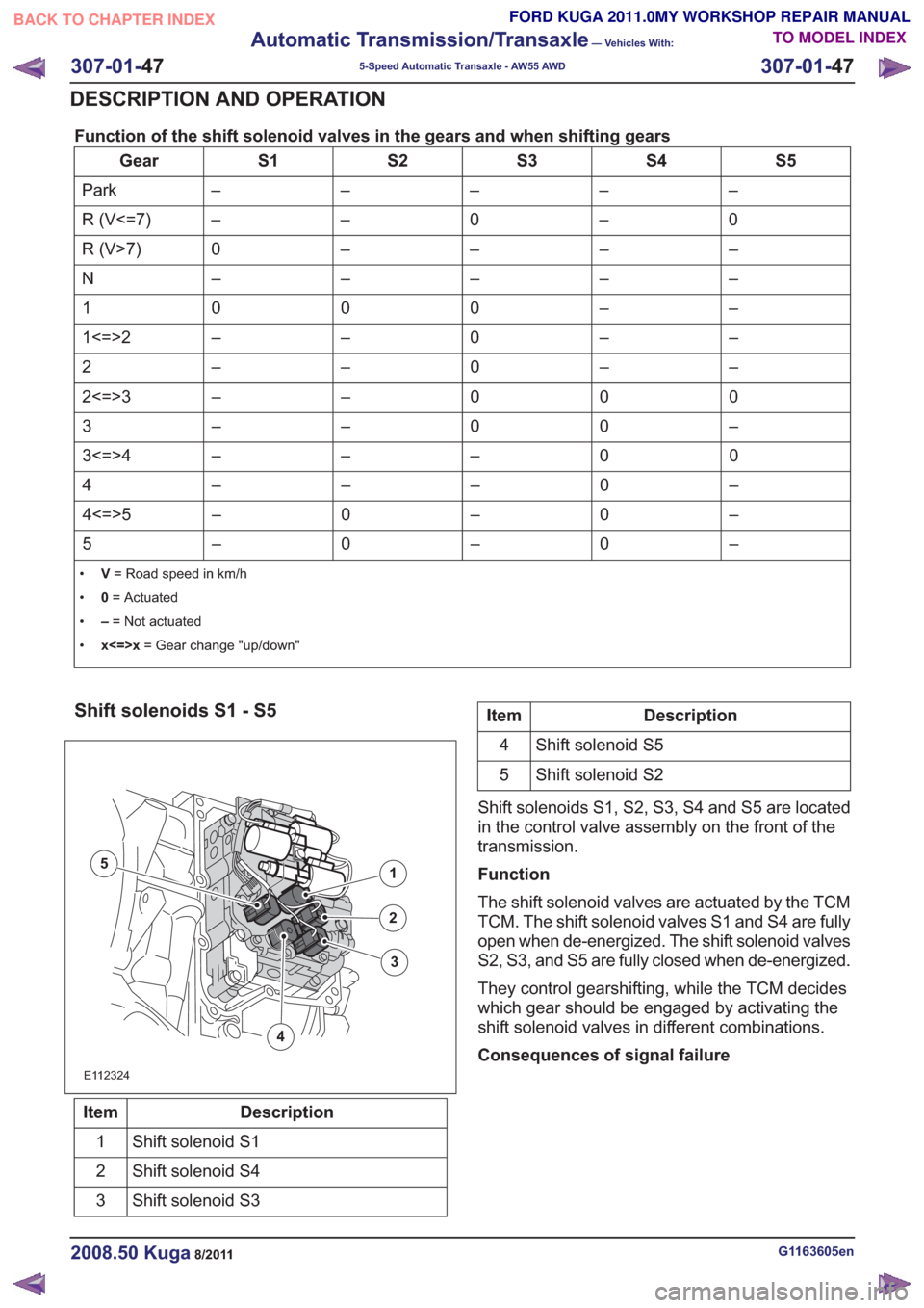
Function of the shift solenoid valves in the gears and when shifting gears
S5
S4
S3
S2
S1
Gear
–
–
–
–
–
Park
0
–
0
–
–
R (V<=7)
–
–
–
–
0
R (V>7)
–
–
–
–
–
N
–
–
0
0
0
1
–
–
0
–
–
1<=>2
–
–
0
–
–
2
0
0
0
–
–
2<=>3
–
0
0
–
–
3
0
0
–
–
–
3<=>4
–
0
–
–
–
4
–
0
–
0
–
4<=>5
–
0
–
0
–
5
• V= Road speed in km/h
• 0= Actuated
• –= Not actuated
• x<=>x = Gear change "up/down"
Shift solenoids S1 - S5
E112324
1
2
4
5
3
Description
Item
Shift solenoid S1
1
Shift solenoid S4
2
Shift solenoid S3
3
Description
Item
Shift solenoid S5
4
Shift solenoid S2
5
Shift solenoids S1, S2, S3, S4 and S5 are located
in the control valve assembly on the front of the
transmission.
Function
The shift solenoid valves are actuated by the TCM
TCM. The shift solenoid valves S1 and S4 are fully
open when de-energized. The shift solenoid valves
S2, S3, and S5 are fully closed when de-energized.
They control gearshifting, while the TCM decides
which gear should be engaged by activating the
shift solenoid valves in different combinations.
Consequences of signal failure
G1163605en2008.50 Kuga8/2011
307-01- 47
Automatic Transmission/Transaxle
— Vehicles With:
5-Speed Automatic Transaxle - AW55 AWD
307-01- 47
DESCRIPTION AND OPERATION
TO MODEL INDEX
BACK TO CHAPTER INDEX
FORD KUGA 2011.0MY WORKSHOP REPAIR MANUAL
Page 1872 of 2057
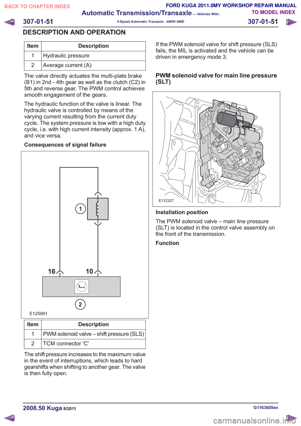
Description
Item
Hydraulic pressure
1
Average current (A)
2
The valve directly actuates the multi-plate brake
(B1) in 2nd - 4th gear as well as the clutch (C2) in
5th and reverse gear. The PWM control achieves
smooth engagement of the gears.
The hydraulic function of the valve is linear. The
hydraulic valve is controlled by means of the
varying current resulting from the current duty
cycle. The system pressure is low with a high duty
cycle, i.e. with high current intensity (approx. 1 A),
and vice versa.
Consequences of signal failure
E125991
2
1
Description
Item
PWM solenoid valve – shift pressure (SLS)
1
TCM connector 'C'
2
The shift pressure increases to the maximum value
in the event of interruptions, which leads to hard
gearshifts when shifting to another gear. The valve
is then fully open. If the PWM solenoid valve for shift pressure (SLS)
fails, the MIL is activated and the vehicle can be
driven in emergency mode 3.
PWM solenoid valve for main line pressure
(SLT)
E112327
Installation position
The PWM solenoid valve – main line pressure
(SLT) is located in the control valve assembly on
the front of the transmission.
Function
G1163605en2008.50 Kuga8/2011
307-01-
51
Automatic Transmission/Transaxle
— Vehicles With:
5-Speed Automatic Transaxle - AW55 AWD
307-01- 51
DESCRIPTION AND OPERATION
TO MODEL INDEX
BACK TO CHAPTER INDEX
FORD KUGA 2011.0MY WORKSHOP REPAIR MANUAL
Page 1874 of 2057
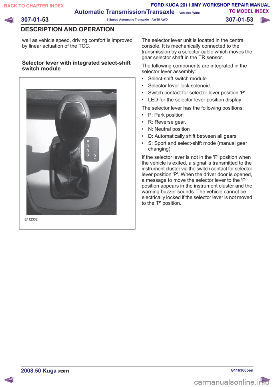
well as vehicle speed, driving comfort is improved
by linear actuation of the TCC.
Selector lever with integrated select-shift
switch module
E112332
The selector lever unit is located in the central
console. It is mechanically connected to the
transmission by a selector cable which moves the
gear selector shaft in the TR sensor.
The following components are integrated in the
selector lever assembly:
• Select-shift switch module
• Selector lever lock solenoid.
• Switch contact for selector lever position 'P'
• LED for the selector lever position display
The selector lever has the following positions:
• P: Park position
• R: Reverse gear.
• N: Neutral position
• D: Automatically shift between all gears
• S: Sport and select-shift mode (manual gearchanging)
If the selector lever is not in the 'P' position when
the vehicle is exited, a signal is transmitted to the
instrument cluster via the switch contact for selector
lever position 'P'. When the driver door is opened,
a message to move the selector lever to the 'P'
position appears in the instrument cluster and the
warning buzzer sounds. The vehicle cannot be
electrically locked if the selector lever is not moved
to the 'P' position.
G1163605en2008.50 Kuga8/2011
307-01- 53
Automatic Transmission/Transaxle
— Vehicles With:
5-Speed Automatic Transaxle - AW55 AWD
307-01- 53
DESCRIPTION AND OPERATION
TO MODEL INDEX
BACK TO CHAPTER INDEX
FORD KUGA 2011.0MY WORKSHOP REPAIR MANUAL
Page 1931 of 2057
SECTION 307-05 Automatic Transmission/Transaxle
External Controls
— Vehicles With: 5-Speed Automatic Transaxle - AW55 AWD/6-Speed
Automatic Transaxle - 6DCT450
VEHICLE APPLICATION: 2008.50 Kuga
PA G E
CONTENTS
SPECIFICATIONS
307-05-2
Specifications ........................................................................\
..............................................
DESCRIPTION AND OPERATION 307-05-3
External Controls (Component Location) ........................................................................\
...
307-05-4
External Controls (Overview) ........................................................................\
......................
307-05-4
Transmission range selector ........................................................................\
......................
307-05-4
Transmission range selector lever emergency release ..................................................
GENERAL PROCEDURES
307-05-6
Selector Lever Cable Adjustment — Vehicles With: 5-Speed Automatic Transaxle - AW55
AWD ........................................................................\
..........................................................
REMOVAL AND INSTALLATION 307-05-7
Selector Lever Cable — Vehicles With: 5-Speed Automatic Transaxle - AW55 AWD .......
307-05-11
Selector Lever Assembly — Vehicles With: 5-Speed Automatic Transaxle - AW55 AWD ..
307-05-1
Automatic Transmission/Transaxle External
Controls
— Vehicles With: 5-Speed Automatic Transaxle - AW55 AWD/6-Speed
Automatic Transaxle - 6DCT450
307-05-1
.
TO MODEL INDEX
BACK TO CHAPTER INDEX
FORD KUGA 2011.0MY WORKSHOP REPAIR MANUAL
Page 1933 of 2057
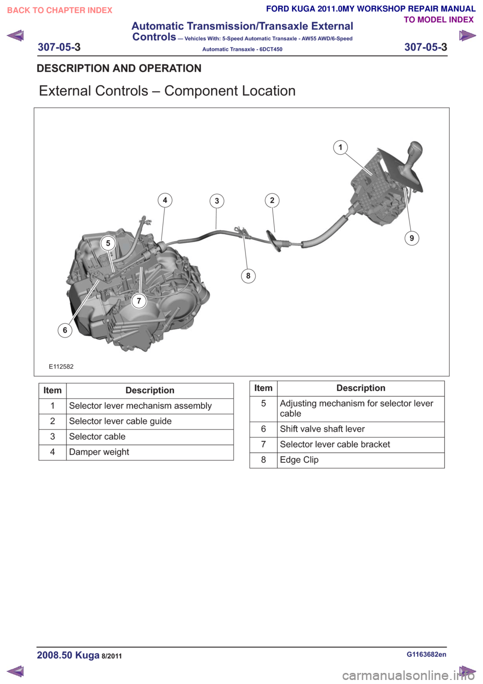
External Controls – Component Location
1
234
5
6
8
9
7
E112582
Description
Item
Selector lever mechanism assembly
1
Selector lever cable guide
2
Selector cable
3
Damper weight
4Description
Item
Adjusting mechanism for selector lever
cable
5
Shift valve shaft lever
6
Selector lever cable bracket
7
Edge Clip
8
G1163682en2008.50 Kuga8/2011
DESCRIPTION AND OPERATION
TO MODEL INDEX
BACK TO CHAPTER INDEX
FORD KUGA 2011.0MY WORKSHOP REPAIR MANUAL
307-05-
3
Automatic Transmission/Transaxle External
Controls
— Vehicles With: 5-Speed Automatic Transaxle - AW55 AWD/6-Speed
Automatic Transaxle - 6DCT450
307-05-3
.
Page 1941 of 2057
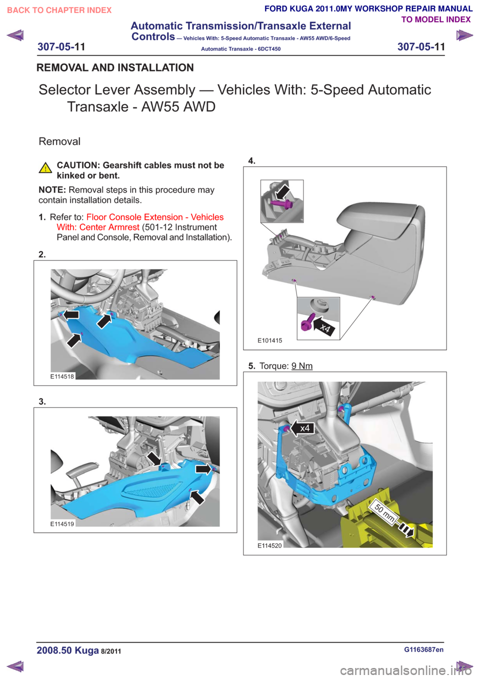
Selector Lever Assembly — Vehicles With: 5-Speed AutomaticTransaxle - AW55 AWD
Removal
CAUTION: Gearshift cables must not be
kinked or bent.
NOTE: Removal steps in this procedure may
contain installation details.
1. Refer to: Floor Console Extension - Vehicles
With: Center Armrest (501-12 Instrument
Panel and Console, Removal and Installation).
2.
E114518
3.
E114519
4.
x4x4
E101415
5. Torque: 9Nm
50 mm
x4
50 mm
x4
E114520
G1163687en2008.50 Kuga8/2011
REMOVAL AND INSTALLATION
TO MODEL INDEX
BACK TO CHAPTER INDEX
FORD KUGA 2011.0MY WORKSHOP REPAIR MANUAL
307-05-
11
Automatic Transmission/Transaxle External
Controls
— Vehicles With: 5-Speed Automatic Transaxle - AW55 AWD/6-Speed
Automatic Transaxle - 6DCT450
307-05-11
.