Page 1374 of 2057
Brake Pads(12 234 0)
Special Tool(s)206-005
Retractor, Brake Caliper
Piston
12014
Materials
Specification
Name
WSS-M6C57-A2
Brake Fluid - Super
DOT4
WSS-M12A4-A2 / 1C1J-
19584-BA
Lubricating Paste
Removal
NOTE:
Removal steps in this procedure may
contain installation details.
1. Refer to: Brake System Health and Safety
Precautions (100-00 General Information,
Description and Operation).
2. Refer to: Wheel and Tire (204-04 Wheels and
Tires, Removal and Installation).
3.
E100314
4. WARNING: The brake caliper housing Torx bolts must not be removed.
CAUTION: Make sure that no load is
placed on the brake hose.
Torque: 28
Nm
E94825
12
3
5.
E100312
6.
E100313
G1001203en2008.50 Kuga8/2011
206-03- 2
Front Disc Brake
206-03- 2
REMOVAL AND INSTALLATION
TO MODEL INDEX
BACK TO CHAPTER INDEX
FORD KUGA 2011.0MY WORKSHOP REPAIR MANUAL
Page 1375 of 2057
7.Special Tool(s): 206-005
E94902
206-005
Installation
1. NOTE:
Material: Lubricating Paste (WSS-M12A4-A2 /1C1J-19584-BA) grease
E117895
12
2. Material: Lubricating Paste (WSS-M12A4-A2 /
1C1J-19584-BA) grease
E117451
3. To install, reverse the removal procedure. 4.Depress the brake pedal, check the brake fluid
level in the brake fluid reservoir and top up as
necessary with brake fluid.
Material: Brake Fluid - Super DOT4
(WSS-M6C57-A2) brake fluid
G1001203en2008.50 Kuga8/2011
206-03- 3
Front Disc Brake
206-03- 3
REMOVAL AND INSTALLATION
TO MODEL INDEX
BACK TO CHAPTER INDEX
FORD KUGA 2011.0MY WORKSHOP REPAIR MANUAL
Page 1377 of 2057
Front Brake Flexible Hose
Removal
CAUTION:
Refer to:Brake System Health and Safety
Precautions (100-00 General Information,
Description and Operation).
NOTE: Removal steps in this procedure may
contain installation details. 1.
Refer to: Wheel and Tire (204-04 Wheels and
Tires, Removal and Installation).
2. WARNINGS:
Make sure that no load is placed on the
brake hose.
Be prepared to collect escaping fluid.
CAUTION: Make sure that all openings
are sealed.
1. Torque: 15
Nm
4. Torque: 23Nm
E99419
1
2
3
4
Installation
1. To install, reverse the removal procedure.
2. Refer to: Component Bleeding (206-00 Brake
System - General Information, General
Procedures).
G1001206en2008.50 Kuga8/2011
206-03- 5
Front Disc Brake
206-03- 5
REMOVAL AND INSTALLATION
TO MODEL INDEX
BACK TO CHAPTER INDEX
FORD KUGA 2011.0MY WORKSHOP REPAIR MANUAL
Page 1379 of 2057

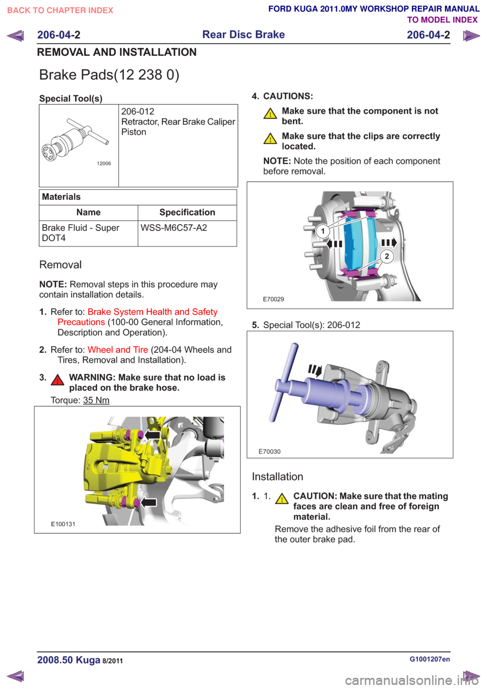
Brake Pads(12 238 0)
Special Tool(s)206-012
Retractor, Rear Brake Caliper
Piston
12006
Materials
Specification
Name
WSS-M6C57-A2
Brake Fluid - Super
DOT4
Removal
NOTE: Removal steps in this procedure may
contain installation details.
1. Refer to: Brake System Health and Safety
Precautions (100-00 General Information,
Description and Operation).
2. Refer to: Wheel and Tire (204-04 Wheels and
Tires, Removal and Installation).
3. WARNING: Make sure that no load is placed on the brake hose.
Torque: 35Nm
E100131
4. CAUTIONS:
Make sure that the component is not
bent.
Make sure that the clips are correctly
located.
NOTE: Note the position of each component
before removal.
E70029
1
2
5. Special Tool(s): 206-012
E70030
Installation
1. 1. CAUTION: Make sure that the mating
faces are clean and free of foreign
material.
Remove the adhesive foil from the rear of
the outer brake pad.
G1001207en2008.50 Kuga8/2011
206-04- 2
Rear Disc Brake
206-04- 2
REMOVAL AND INSTALLATION
TO MODEL INDEX
BACK TO CHAPTER INDEX
FORD KUGA 2011.0MY WORKSHOP REPAIR MANUAL
Page 1380 of 2057
E139523
11
22
2.To install, reverse the removal procedure.
3. Depress the brake pedal, check the brake fluid
level in the brake fluid reservoir and top up as
necessary with brake fluid.
Material: Brake Fluid - Super DOT4
(WSS-M6C57-A2) brake fluid
G1001207en2008.50 Kuga8/2011
206-04- 3
Rear Disc Brake
206-04- 3
REMOVAL AND INSTALLATION
TO MODEL INDEX
BACK TO CHAPTER INDEX
FORD KUGA 2011.0MY WORKSHOP REPAIR MANUAL
Page 1381 of 2057

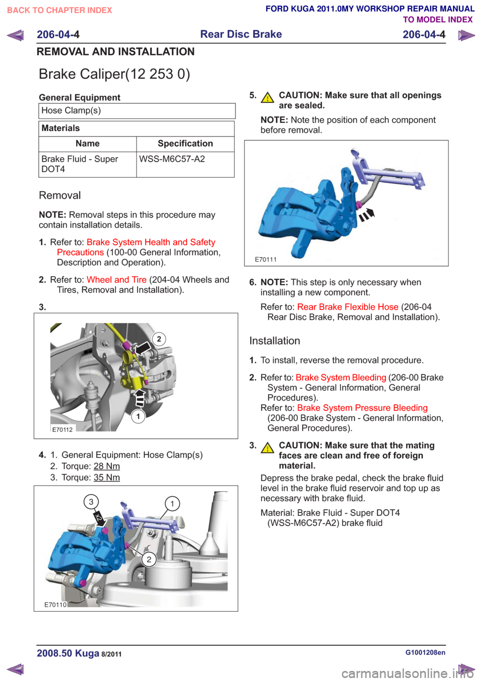
Brake Caliper(12 253 0)
General EquipmentHose Clamp(s)
Materials
Specification
Name
WSS-M6C57-A2
Brake Fluid - Super
DOT4
Removal
NOTE: Removal steps in this procedure may
contain installation details.
1. Refer to: Brake System Health and Safety
Precautions (100-00 General Information,
Description and Operation).
2. Refer to: Wheel and Tire (204-04 Wheels and
Tires, Removal and Installation).
3.
E70112
1
2
4. General Equipment: Hose Clamp(s)
1.
2. Torque: 28
Nm
3. Torque: 35Nm
E70110
1
2
x2
3
5. CAUTION: Make sure that all openings
are sealed.
NOTE: Note the position of each component
before removal.
E70111
6. NOTE: This step is only necessary when
installing a new component.
Refer to: Rear Brake Flexible Hose (206-04
Rear Disc Brake, Removal and Installation).
Installation
1. To install, reverse the removal procedure.
2. Refer to: Brake System Bleeding (206-00 Brake
System - General Information, General
Procedures).
Refer to: Brake System Pressure Bleeding
(206-00 Brake System - General Information,
General Procedures).
3.
CAUTION: Make sure that the mating
faces are clean and free of foreign
material.
Depress the brake pedal, check the brake fluid
level in the brake fluid reservoir and top up as
necessary with brake fluid.
Material: Brake Fluid - Super DOT4 (WSS-M6C57-A2) brake fluid
G1001208en2008.50 Kuga8/2011
206-04- 4
Rear Disc Brake
206-04- 4
REMOVAL AND INSTALLATION
TO MODEL INDEX
BACK TO CHAPTER INDEX
FORD KUGA 2011.0MY WORKSHOP REPAIR MANUAL
Page 1382 of 2057
Rear Brake Flexible Hose
Removal
CAUTION:
Refer to:Brake System Health and Safety
Precautions (100-00 General Information,
Description and Operation).
NOTE: Removal steps in this procedure may
contain installation details. 1.
Refer to: Wheel and Tire (204-04 Wheels and
Tires, Removal and Installation).
2. WARNINGS:
Make sure that no load is placed on the
brake hose.
Be prepared to collect escaping fluid.
CAUTION: Make sure that all openings
are sealed.
1. Torque: 15
Nm
E99425
1
2
3
G1001210en2008.50 Kuga8/2011
206-04- 5
Rear Disc Brake
206-04- 5
REMOVAL AND INSTALLATION
TO MODEL INDEX
BACK TO CHAPTER INDEX
FORD KUGA 2011.0MY WORKSHOP REPAIR MANUAL
Page 1402 of 2057
Brake Master Cylinder — 2.5L Duratec (147kW/200PS) -VI5(12 343 0)
Removal
NOTE: Removal steps in this procedure may
contain installation details.
1. Refer to: Brake System Health and Safety
Precautions (100-00 General Information,
Description and Operation).
2. Connect one end of a suitable piece of clear
plastic pipe to the brake caliper bleed nipple
1.
and place the other end into a suitable
container.
2. Loosen the bleed nipple.
3. Depress the brake pedal until no more brake fluid comes through the bleed nipple.
4. Tighten the bleed nipple.
5. Repeat the draining procedure on the opposite side brake caliper.
E86914
Left-hand drive vehicles
3. CAUTION: Make sure that all openings are sealed.
1. Torque: 18Nm
2.NOTE: Make sure that new components are
installed.
Torque: 25
Nm
G1174985en2008.50 Kuga8/2011
206-06- 5
Hydraulic Brake Actuation
206-06- 5
REMOVAL AND INSTALLATION
TO MODEL INDEX
BACK TO CHAPTER INDEX
FORD KUGA 2011.0MY WORKSHOP REPAIR MANUAL