2011 FORD KUGA EGR
[x] Cancel search: EGRPage 1876 of 2057
Description
Item
Drive
3
Intake side
4
Delivery side
5
The fluid pump operates on the principle of a
G-rotor fluid pump.
The fluid pump draws transmission fluid from the
fluid pan, builds up fluid pressure and then supplies
it to the valve body.
The fluid pump is driven by the crankshaft via the
torque converter housing.
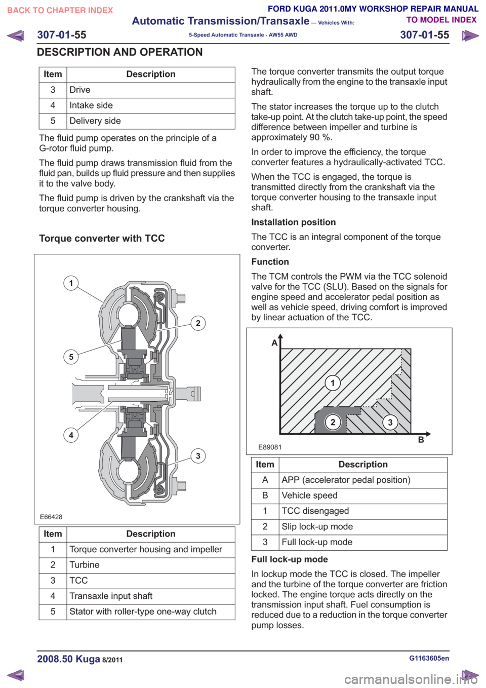
Torque converter with TCC
E66428E66428
1
2
3
5
4
Description
Item
Torque converter housing and impeller
1
Turbine
2
TCC3
Transaxle input shaft
4
Stator with roller-type one-way clutch
5 The torque converter transmits the output torque
hydraulically from the engine to the transaxle input
shaft.
The stator increases the torque up to the clutch
take-up point. At the clutch take-up point, the speed
difference between impeller and turbine is
approximately 90 %.
In order to improve the efficiency, the torque
converter features a hydraulically-activated TCC.
When the TCC is engaged, the torque is
transmitted directly from the crankshaft via the
torque converter housing to the transaxle input
shaft.
Installation position
The TCC is an integral component of the torque
converter.
Function
The TCM controls the PWM via the TCC solenoid
valve for the TCC (SLU). Based on the signals for
engine speed and accelerator pedal position as
well as vehicle speed, driving comfort is improved
by linear actuation of the TCC.
E89081
1
A
B
23
Description
Item
APP (accelerator pedal position)
A
Vehicle speed
B
TCC disengaged
1
Slip lock-up mode
2
Full lock-up mode
3
Full lock-up mode
In lockup mode the TCC is closed. The impeller
and the turbine of the torque converter are friction
locked. The engine torque acts directly on the
transmission input shaft. Fuel consumption is
reduced due to a reduction in the torque converter
pump losses.
G1163605en2008.50 Kuga8/2011
307-01- 55
Automatic Transmission/Transaxle
— Vehicles With:
5-Speed Automatic Transaxle - AW55 AWD
307-01- 55
DESCRIPTION AND OPERATION
TO MODEL INDEX
BACK TO CHAPTER INDEX
FORD KUGA 2011.0MY WORKSHOP REPAIR MANUAL
Page 1879 of 2057
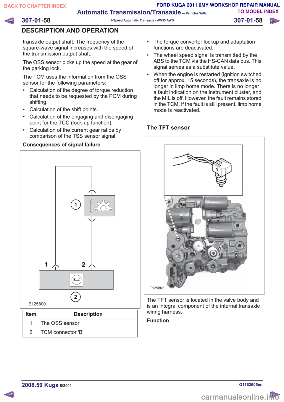
transaxle output shaft. The frequency of the
square-wave signal increases with the speed of
the transmission output shaft.
The OSS sensor picks up the speed at the gear of
the parking lock.
The TCM uses the information from the OSS
sensor for the following parameters:
• Calculation of the degree of torque reductionthat needs to be requested by the PCM during
shifting.
• Calculation of the shift points.
• Calculation of the engaging and disengaging point for the TCC (lock-up function).
• Calculation of the current gear ratios by comparison of the TSS sensor signal.
Consequences of signal failure
E125800
1 2
2
1
Description
Item
The OSS sensor
1
TCM connector 'B'
2 • The torque converter lockup and adaptation
functions are deactivated.
• The wheel speed signal is transmitted by the ABS to the TCM via the HS-CAN data bus. This
signal serves as a substitute value.
• When the engine is restarted (ignition switched off for approx. 15 seconds), the transaxle is no
longer in limp home mode. There is no longer
a fault indication on the instrument cluster, and
the MIL is off. However, the fault remains stored
in the TCM. If the fault is still present, limp home
mode is reactivated.
The TFT sensor
E125802
The TFT sensor is located in the valve body and
is an integral component of the internal transaxle
wiring harness.
Function
G1163605en2008.50 Kuga8/2011
307-01- 58
Automatic Transmission/Transaxle
— Vehicles With:
5-Speed Automatic Transaxle - AW55 AWD
307-01- 58
DESCRIPTION AND OPERATION
TO MODEL INDEX
BACK TO CHAPTER INDEX
FORD KUGA 2011.0MY WORKSHOP REPAIR MANUAL
Page 2007 of 2057
Description
Item
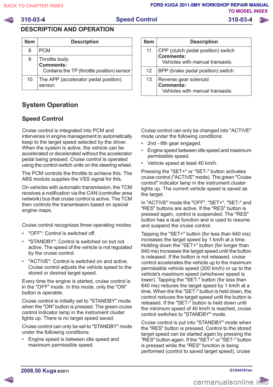
PCM
8
Throttle body
Comments:Contains the TP (throttle position) sensor
9
The APP (accelerator pedal position)
sensor.
10Description
Item
CPP (clutch pedal position) switch
Comments:Vehicles with manual transaxle.
11
BPP (brake pedal position) switch
12
Reverse gear solenoid
Comments:Vehicles with manual transaxle.
13
System Operation
Speed Control
Cruise control is integrated into PCM and
intervenes in engine management to automatically
keep to the target speed selected by the driver.
When the system is active, the vehicle can be
accelerated or decelerated without the accelerator
pedal being pressed. Cruise control is operated
using the control switch units on the steering wheel.
The PCM controls the throttle to achieve this. The
ABS module supplies the VSS signal for this.
On vehicles with automatic transmission, the TCM
receives a notification via the CAN (controller area
network) bus that cruise control is active. The TCM
then controls the transmission based on special
engine maps.
Cruise control recognizes three operating modes:
• "OFF": Control is switched off.
• "STANDBY": Control is switched on but not
active. The speed of the vehicle is not regulated
by the cruise control.
• "ACTIVE": Control is switched on and active. Cruise control adjusts the vehicle speed to the
stored or desired target speed.
Every time the engine is started, cruise control is
in the "OFF" mode. In this mode, only the "ON"
button is operable.
Cruise control is initially set to "STANDBY" mode
when the "ON" button is pressed. The green cruise
control indicator lamp in the instrument cluster
lights up. There is no target speed saved.
Cruise control can only be set to "STANDBY" mode
under the following conditions:
• Engine speed is between idle speed and maximum permissible speed. Cruise control can only be changed into "ACTIVE"
mode under the following conditions:
• 2nd - 6th gear engaged.
• Engine speed between idle speed and maximum
permissible speed.
• Vehicle speed at least 40 km/h.
Pressing the "SET+" or "SET-" button activates
cruise control ("ACTIVE" mode). The green "Cruise
control" indicator lamp in the instrument cluster
lights up. The current vehicle speed is saved as
the target.
In "ACTIVE" mode the "OFF", "SET+", "SET-" and
"RES" buttons are active. If the "RES" button is
pressed again, control is suspended. The "RES"
button has a dual function and is used to resume
and suspend the cruise control.
Tapping the "SET+" button (for less than 640 ms)
increases the target speed by 1 km/h at a time.
Holding down the "SET+" button (for longer than
640 ms) increases the target speed until the button
is released. If the button is not released, cruise
control accelerates the vehicle up to the maximum
permissible vehicle speed (200 km/h) or up to the
vehicle's maximum speed (whichever speed is
lower). Tapping the "SET-" button (for less than
640 ms) reduces the target speed by 1 km/h at a
time. When the the "SET-" button is held down, the
control reduces the target speed until the button is
released. If the "SET-" button is held down until
the minimum speed of 40 km/h is reached, cruise
control switches to "STANDBY" mode.
Cruise control is put into "STANDBY" mode when
the "RES" button is pressed. Control to the stored
target speed can be started again by pressing the
"RES" button again. If the "SET+" or "SET-" button
is pressed while the "RES" function is being
performed (control to saved target speed), cruise
G1044191en2008.50 Kuga8/2011
310-03- 4
Speed Control
310-03- 4
DESCRIPTION AND OPERATION
TO MODEL INDEX
BACK TO CHAPTER INDEX
FORD KUGA 2011.0MY WORKSHOP REPAIR MANUAL
Page 2014 of 2057
Climate Control System
Refer to Wiring Diagrams Section 412-00, for
schematic and connector information.
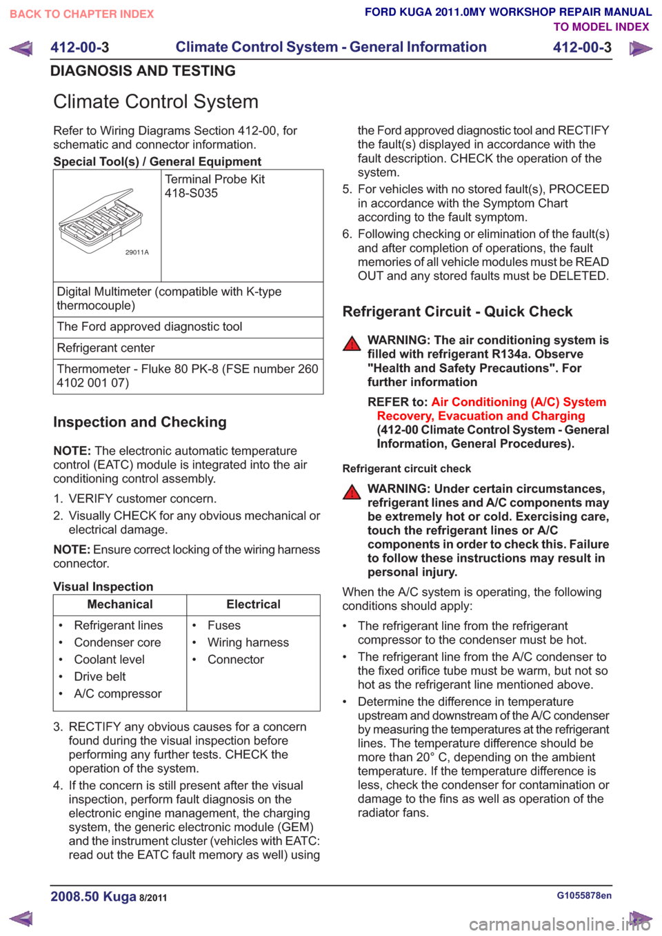
Special Tool(s) / General EquipmentTerminal Probe Kit
418-S035
29011A
Digital Multimeter (compatible with K-type
thermocouple)
The Ford approved diagnostic tool
Refrigerant center
Thermometer - Fluke 80 PK-8 (FSE number 260
4102 001 07)
Inspection and Checking
NOTE:The electronic automatic temperature
control (EATC) module is integrated into the air
conditioning control assembly.
1. VERIFY customer concern.
2. Visually CHECK for any obvious mechanical or electrical damage.
NOTE: Ensure correct locking of the wiring harness
connector.
Visual Inspection
Electrical
Mechanical
• Fuses
• Wiring harness
• Connector
• Refrigerant lines
• Condenser core
• Coolant level
• Drive belt
• A/C compressor
3. RECTIFY any obvious causes for a concern found during the visual inspection before
performing any further tests. CHECK the
operation of the system.
4. If the concern is still present after the visual inspection, perform fault diagnosis on the
electronic engine management, the charging
system, the generic electronic module (GEM)
and the instrument cluster (vehicles with EATC:
read out the EATC fault memory as well) using the Ford approved diagnostic tool and RECTIFY
the fault(s) displayed in accordance with the
fault description. CHECK the operation of the
system.
5. For vehicles with no stored fault(s), PROCEED in accordance with the Symptom Chart
according to the fault symptom.
6. Following checking or elimination of the fault(s) and after completion of operations, the fault
memories of all vehicle modules must be READ
OUT and any stored faults must be DELETED.
Refrigerant Circuit - Quick Check
WARNING: The air conditioning system is
filled with refrigerant R134a. Observe
"Health and Safety Precautions". For
further information
REFER to: Air Conditioning (A/C) System
Recovery, Evacuation and Charging
(412-00 Climate Control System - General
Information, General Procedures).
Refrigerant circuit check
WARNING: Under certain circumstances,
refrigerant lines and A/C components may
be extremely hot or cold. Exercising care,
touch the refrigerant lines or A/C
components in order to check this. Failure
to follow these instructions may result in
personal injury.
When the A/C system is operating, the following
conditions should apply:
• The refrigerant line from the refrigerant compressor to the condenser must be hot.
• The refrigerant line from the A/C condenser to the fixed orifice tube must be warm, but not so
hot as the refrigerant line mentioned above.
• Determine the difference in temperature upstream and downstream of the A/C condenser
by measuring the temperatures at the refrigerant
lines. The temperature difference should be
more than 20° C, depending on the ambient
temperature. If the temperature difference is
less, check the condenser for contamination or
damage to the fins as well as operation of the
radiator fans.
G1055878en2008.50 Kuga8/2011
412-00- 3
Climate Control System - General Information
412-00- 3
DIAGNOSIS AND TESTING
TO MODEL INDEX
BACK TO CHAPTER INDEX
FORD KUGA 2011.0MY WORKSHOP REPAIR MANUAL
Page 2015 of 2057
• The refrigerant line between the fixed orificetube and the evaporator must be cold from the
point where the fixed orifice tube is installed.
Depending on the weather, the refrigerant line
may also have ice on its surface.
• The refrigerant line between the evaporator and the A/C compressor including the dehydrator
must be cold.
Evaporator outlet line temperature test
To test the power of the A/C system, the
temperature at the evaporator outlet line must be
measured. To do this, the following preconditions
must be met:
• Open all windows.
• Set the air distribution to the defrost/dashboardposition and open all the ventilation nozzles.
• DO NOT switch on recirculated air.
• Select lowest blower switch setting.
• Select lowest temperature setting.
NOTE: The temperature measurement cannot be
done with a thermometer which makes no contact.
The surface reflection from the metal line may
cause incorrect readings.
Connect the temperature sensor (Fluke 80 PK-8)
to the outlet line of the evaporator. Locate the
temperature sensor as close as possible to the
evaporator. Connect the temperature sensor to the
multimeter.
Start the engine and allow it to run at idle speed
for several minutes.
Switch on the A/C.
After three minutes, measure the surface
temperature of the evaporator outlet line.
If the temperature measured is 4° C or lower, the
A/C system is OK. If the temperature is higher, the
A/C system may be under-filled. For further
information, refer to
REFER to: Air Conditioning (A/C) System
Recovery, Evacuation and Charging (412-00
Climate Control System - General Information,
General Procedures).
Frequent faults and their causes
If the cooling power of the A/C system is not
adequate, make certain that the temperature
control flap(s) is/are operating correctly. • No or poor cooling performance:
– Blockage or narrowing of a refrigerant line orin the dehydrator. The location of the
blockage or narrowing can easily be located
by temperature comparisons at the
refrigerant lines and the dehydrator. The
blockage or restriction is located at the point
where the temperature difference is
identified. Note: A temperature difference
in the area of the fixed orifice tube is
normal. If the location of the blockage or
narrowing is found, check the corresponding
component and renew as applicable.
• Sudden drop in cooling performance (after the air conditioning has been switched off for
approx. 5 minutes, the cooling performance
returns to normal):
– The cause is an iced-up fixed orifice tubebecause of moisture in the refrigerant circuit.
In order to ensure that moisture is completely
removed from the refrigerant circuit, the
dehydrator should be renewed and the
evacuation time should be extended to 2-3
hours. For further information
REFER to: Air Conditioning (A/C) System
Recovery, Evacuation and Charging
(412-00 Climate Control System - General
Information, General Procedures).
Sequence of A/C Request Signal
NOTE: The electronic automatic temperature
control (EATC) module is integrated into the air
conditioning control assembly.
NOTE: The generic electronic module (GEM) is
an integral part of the central junction box (CJB).
After actuating the A/C ON/OFF switch integrated
into the A/C control assembly, an A/C request
signal is sent from the A/C control assembly
(vehicles with EATC: EATC module) to the GEM.
From there, the signal is sent to the instrument
cluster via the MS-CAN bus. A gateway is installed
in the instrument cluster, which establishes the
connection between the MS-CAN bus and the
HS-CAN bus.
After the signal has been converted in the gateway,
it is relayed to the powertrain control module (PCM)
via the HS-CAN bus. Once all the required
parameters have been met, the PCM switches on
the refrigerant compressor and thus the A/C system
via the A/C clutch relay.
G1055878en2008.50 Kuga8/2011
412-00- 4
Climate Control System - General Information
412-00- 4
DIAGNOSIS AND TESTING
TO MODEL INDEX
BACK TO CHAPTER INDEX
FORD KUGA 2011.0MY WORKSHOP REPAIR MANUAL
Page 2052 of 2057
Control assembly, climate control -
vehicles with automatic temperature
control
E97722
Vehicles with automatic temperature control have
a control assembly with the following button
operated functions:
• Switching the air conditioning system on andoff
• Temperature adjustment for the driver's side/front passenger's side
• Switching the windshield defrost function on and off
• Switching the electronic automatic climate control and the dual mode on and off
• Air distribution
• Blower Control
• Switching off the dual automatic climate control
• Recirculated air control
Control assembly, climate control -
vehicles with DVD navigation system with
a touch screen
E97723
On vehicles with a DVD navigation system with a
touch screen, the control buttons for the automatic
temperature control (climate control) are integrated in this unit. In addition, all heating and air
conditioning functions can be controlled via the
touchscreen. The information exchange takes place
on the mid-speed CAN bus (MS-CAN).
Climate control module - vehicles with DVD
navigation system with a touch screen
E97724
On vehicles with a DVD navigation system with a
touch screen, the climate control module is
provided as a separate component underneath the
DVD navigation unit. It is actuated via control
buttons or via the navigation touch screen.
Sun sensor - vehicles with automatic
temperature control
E97725
For vehicles with automatic temperature control
the sun sensor determines the intensity of the
sunload. The sunload serves as an additional
parameter for determining the blower air
temperature, the air distribution and the blower
speed.
G1034947en2008.50 Kuga8/2011
412-01-
25
Climate Control
412-01- 25
DESCRIPTION AND OPERATION
TO MODEL INDEX
BACK TO CHAPTER INDEX
FORD KUGA 2011.0MY WORKSHOP REPAIR MANUAL
Page 2053 of 2057
In-vehicle temperature sensor
E97731
The interior temperature sensor measures the
temperature in the passenger compartment and
thereby also helps to control the pre-selected
interior temperature. This is an NTC resistor.
In order to achieve optimum measurement values,
an integrated blower draws air from the interior into
the in-vehicle temperature sensor.
Ambient temperature sensor
E98860
The outside-temperature sensor measures the
ambient temperature outside the vehicle. The
resistance, and so the voltage drop at the sensor,
alter depending on the outside-air temperature.
This is an NTC resistor.
Blower motor
E98855
On vehicles with electronic automatic temperature
control (EATC), a blower motor with brushes is
used.
Blower control module - vehicles equipped
with automatic temperature control
E97726
On vehicles with electronic automatic temperature
control (EATC) a blower control module is fitted
instead of the conventional blower motor resistor.
This is located in the usual position next to the
blower motor, so that the cooling fins of the module
are cooled by the air flow.
The climate control module regulates the blower
control module via a PWM signal, which in turn
regulates the voltage at the blower motor to
between 3 V and 12.8 V, in an infinitely variable
manner.
The blower control module is fitted with a
temperature monitor which continuously monitors
the internal temperature of the module. If the
temperature rises above 105°C, the blower motor
is switched off until the temperature in the module
falls to below 100°C.
If the current rises above the value of 26 A ± 3 A
defined in the blower control module (e.g. high
G1034947en2008.50 Kuga8/2011
412-01-26
Climate Control
412-01- 26
DESCRIPTION AND OPERATION
TO MODEL INDEX
BACK TO CHAPTER INDEX
FORD KUGA 2011.0MY WORKSHOP REPAIR MANUAL