2011 FORD KUGA Power steering
[x] Cancel search: Power steeringPage 1499 of 2057
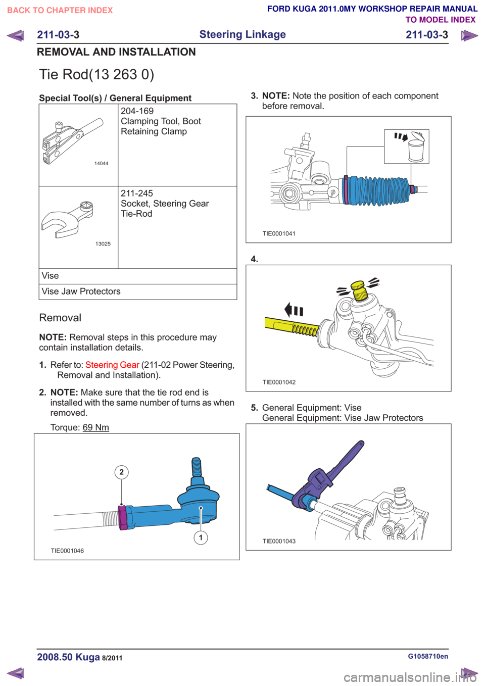
Tie Rod(13 263 0)
Special Tool(s) / General Equipment204-169
Clamping Tool, Boot
Retaining Clamp
14044
211-245
Socket, Steering Gear
Tie-Rod
13025
Vise
Vise Jaw Protectors
Removal
NOTE:Removal steps in this procedure may
contain installation details.
1. Refer to: Steering Gear (211-02 Power Steering,
Removal and Installation).
2. NOTE: Make sure that the tie rod end is
installed with the same number of turns as when
removed.
Torque: 69
Nm
TIE0001046
1
2
3. NOTE: Note the position of each component
before removal.
TIE0001041
4.
TIE0001042
5. General Equipment: Vise
General Equipment: Vise Jaw Protectors
TIE0001043
G1058710en2008.50 Kuga8/2011
211-03- 3
Steering Linkage
211-03- 3
REMOVAL AND INSTALLATION
TO MODEL INDEX
BACK TO CHAPTER INDEX
FORD KUGA 2011.0MY WORKSHOP REPAIR MANUAL
Page 1504 of 2057
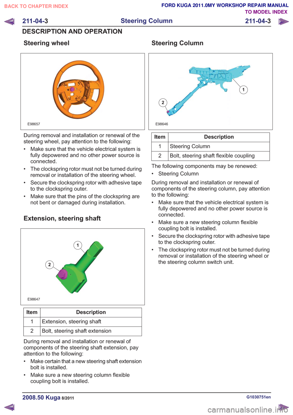
Steering wheel
E98657
During removal and installation or renewal of the
steering wheel, pay attention to the following:
• Make sure that the vehicle electrical system isfully depowered and no other power source is
connected.
• The clockspring rotor must not be turned during removal or installation of the steering wheel.
• Secure the clockspring rotor with adhesive tape to the clockspring outer.
• Make sure that the pins of the clockspring are not bent or damaged during installation.
Extension, steering shaft
E98647
1
2
Description
Item
Extension, steering shaft
1
Bolt, steering shaft extension
2
During removal and installation or renewal of
components of the steering shaft extension, pay
attention to the following:
• Make certain that a new steering shaft extension bolt is installed.
• Make sure a new steering column flexible coupling bolt is installed.
Steering Column
E98646
1
2
Description
Item
Steering Column
1
Bolt, steering shaft flexible coupling
2
The following components may be renewed:
• Steering Column
During removal and installation or renewal of
components of the steering column, pay attention
to the following:
• Make sure that the vehicle electrical system is fully depowered and no other power source is
connected.
• Make sure a new steering column flexible coupling bolt is installed.
• Secure the clockspring rotor with adhesive tape to the clockspring outer.
• The clockspring rotor must not be turned during removal or installation of the steering wheel or
the steering column switch unit.
G1030751en2008.50 Kuga8/2011
211-04- 3
Steering Column
211-04- 3
DESCRIPTION AND OPERATION
TO MODEL INDEX
BACK TO CHAPTER INDEX
FORD KUGA 2011.0MY WORKSHOP REPAIR MANUAL
Page 1506 of 2057
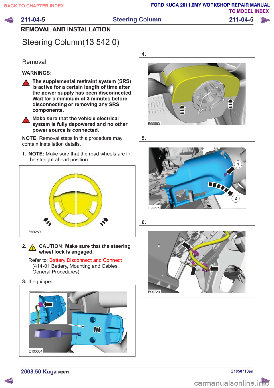
Steering Column(13 542 0)
Removal
WARNINGS:
The supplemental restraint system (SRS)
is active for a certain length of time after
the power supply has been disconnected.
Wait for a minimum of 3 minutes before
disconnecting or removing any SRS
components.
Make sure that the vehicle electrical
system is fully depowered and no other
power source is connected.
NOTE: Removal steps in this procedure may
contain installation details.
1. NOTE: Make sure that the road wheels are in
the straight ahead position.
E99259
2. CAUTION: Make sure that the steering wheel lock is engaged.
Refer to: Battery Disconnect and Connect
(414-01 Battery, Mounting and Cables,
General Procedures).
3. If equipped.
E100834
4.
E95563
5.
E99639
1
2
6.
E99720
G1058718en2008.50 Kuga8/2011
211-04- 5
Steering Column
211-04- 5
REMOVAL AND INSTALLATION
TO MODEL INDEX
BACK TO CHAPTER INDEX
FORD KUGA 2011.0MY WORKSHOP REPAIR MANUAL
Page 1508 of 2057
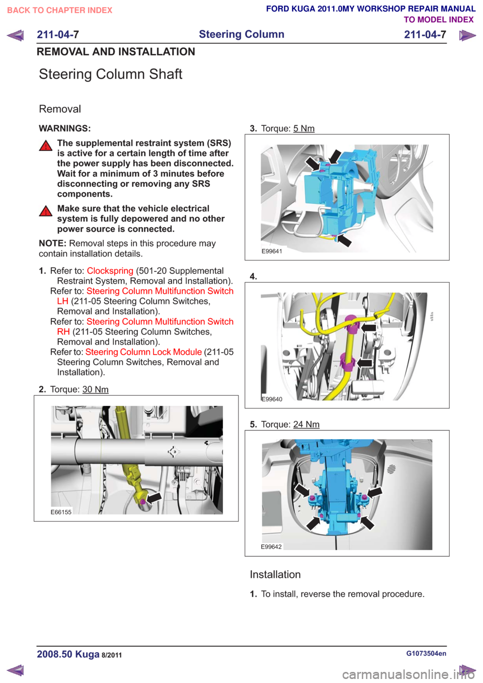
Steering Column Shaft
Removal
WARNINGS:
The supplemental restraint system (SRS)
is active for a certain length of time after
the power supply has been disconnected.
Wait for a minimum of 3 minutes before
disconnecting or removing any SRS
components.
Make sure that the vehicle electrical
system is fully depowered and no other
power source is connected.
NOTE: Removal steps in this procedure may
contain installation details.
1. Refer to: Clockspring (501-20 Supplemental
Restraint System, Removal and Installation).
Refer to: Steering Column Multifunction Switch
LH (211-05 Steering Column Switches,
Removal and Installation).
Refer to: Steering Column Multifunction Switch
RH (211-05 Steering Column Switches,
Removal and Installation).
Refer to: Steering Column Lock Module (211-05
Steering Column Switches, Removal and
Installation).
2. Torque: 30
Nm
E66155
3.Torque: 5Nm
E99641
4.
E99640
5.Torque: 24Nm
E99642
Installation
1.To install, reverse the removal procedure.
G1073504en2008.50 Kuga8/2011
211-04- 7
Steering Column
211-04- 7
REMOVAL AND INSTALLATION
TO MODEL INDEX
BACK TO CHAPTER INDEX
FORD KUGA 2011.0MY WORKSHOP REPAIR MANUAL
Page 1511 of 2057

Steering Column Switches – Overview
Switch unit, steering column
E98629
1
2
3
4
5
Description
Item
Left-hand switch, steering column
1
Switch unit carrier, steering column
2
Right-hand switch, steering column
3Description
Item
Steering wheel rotation sensor
Refer to: Anti-Lock Control - Stability
Assist (206-09 Anti-Lock Control -
Stability Assist, Description and
Operation).
4
Clockspring
5
Clockspring
The clockspring is designed to carry signals
between the RCM and the driver air bag module.
The clockspring is installed on the steering column,
and consists of fixed and moving parts connected
by a coiled Mylar tape with internal conducting
tracks. The Mylar tape is able to 'wind up' and
'unwind' as the steering wheel is rotated,
maintaining electrical contact at all times between
the RCM and the driver air bag module. During removal and installation or renewal of the
clockspring, pay attention to the following:
• Before installation of the clockspring, it must be
aligned according to the installation instructions.
• Make sure that the vehicle electrical system is fully depowered and no other power source is
connected.
• Secure the clockspring rotor with adhesive tape to the clockspring outer.
• The clockspring rotor must not be turned during removal or installation of the steering wheel or
the steering column switch unit.
G1030755en2008.50 Kuga8/2011
211-05- 3
Steering Column Switches
211-05- 3
DESCRIPTION AND OPERATION
TO MODEL INDEX
BACK TO CHAPTER INDEX
FORD KUGA 2011.0MY WORKSHOP REPAIR MANUAL
Page 1671 of 2057
67.Install the following items:
1. Refer to: Battery(414-01 Battery, Mounting
and Cables, Removal and Installation).
2. Refer to: Cowl Panel Grille (501-02 Front
End Body Panels, Removal and
Installation).
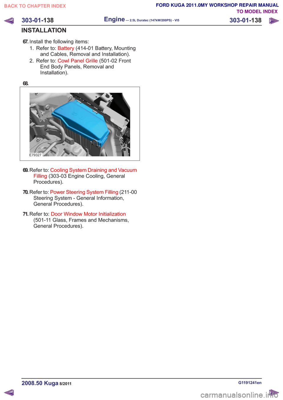
68.
E79327
69. Refer to: Cooling System Draining and Vacuum
Filling (303-03 Engine Cooling, General
Procedures).
70. Refer to: Power Steering System Filling (211-00
Steering System - General Information,
General Procedures).
71. Refer to: Door Window Motor Initialization
(501-11 Glass, Frames and Mechanisms,
General Procedures).
G1191241en2008.50 Kuga8/2011
303-01- 138
Engine— 2.5L Duratec (147kW/200PS) - VI5303-01-
138
INSTALLATION
TO MODEL INDEX
BACK TO CHAPTER INDEX
FORD KUGA 2011.0MY WORKSHOP REPAIR MANUAL
Page 1697 of 2057
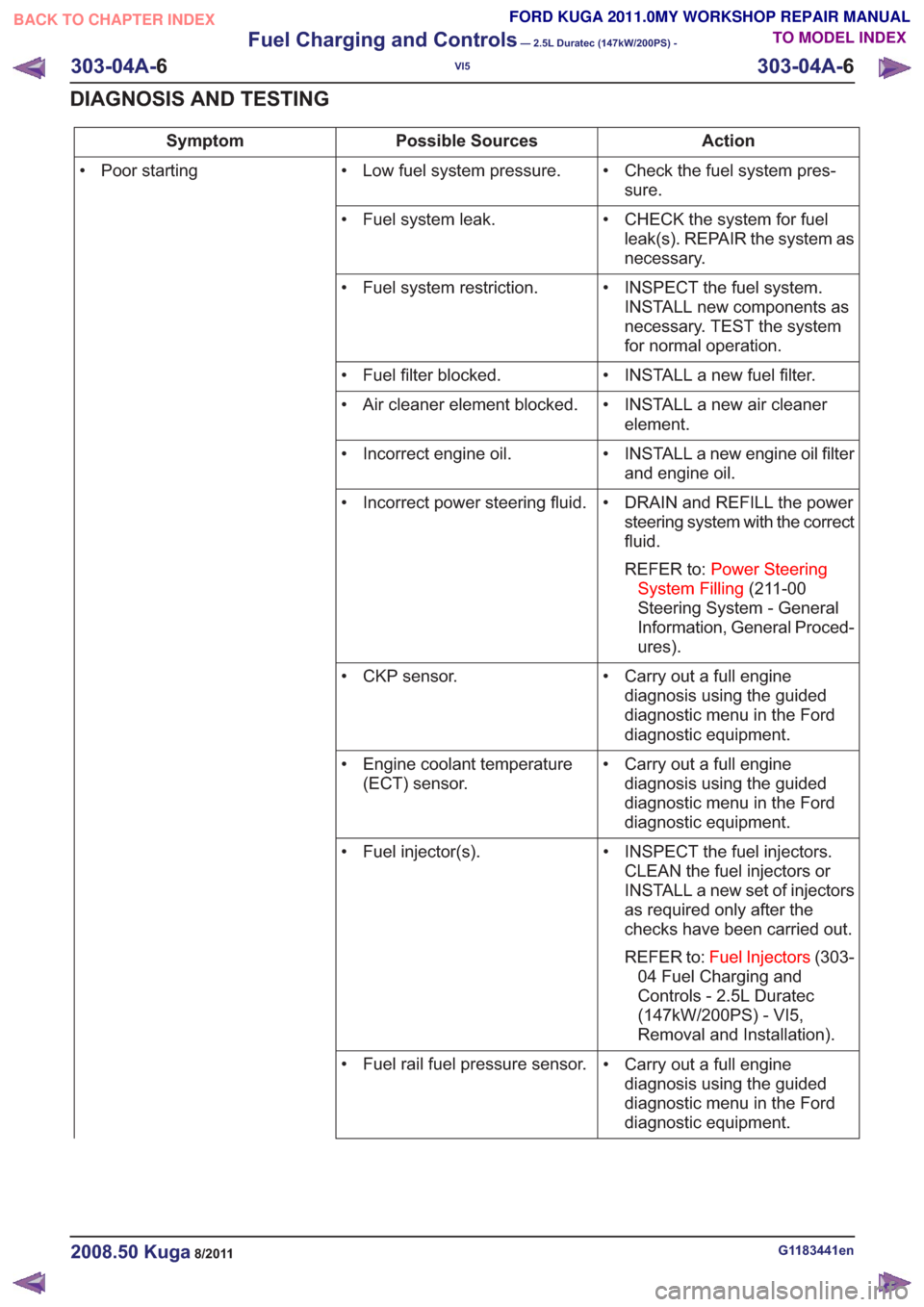
Action
Possible Sources
Symptom
• Check the fuel system pres-sure.
• Low fuel system pressure.
• Poor starting
• CHECK the system for fuelleak(s). REPAIR the system as
necessary.
• Fuel system leak.
• INSPECT the fuel system.INSTALL new components as
necessary. TEST the system
for normal operation.
• Fuel system restriction.
• INSTALL a new fuel filter.
• Fuel filter blocked.
• INSTALL a new air cleanerelement.
• Air cleaner element blocked.
• INSTALL a new engine oil filterand engine oil.
• Incorrect engine oil.
• DRAIN and REFILL the powersteering system with the correct
fluid.
REFER to: Power Steering
System Filling (211-00
Steering System - General
Information, General Proced-
ures).
• Incorrect power steering fluid.
• Carry out a full enginediagnosis using the guided
diagnostic menu in the Ford
diagnostic equipment.
• CKP sensor.
• Carry out a full enginediagnosis using the guided
diagnostic menu in the Ford
diagnostic equipment.
• Engine coolant temperature
(ECT) sensor.
• INSPECT the fuel injectors.CLEAN the fuel injectors or
INSTALL a new set of injectors
as required only after the
checks have been carried out.
REFER to: Fuel Injectors (303-
04 Fuel Charging and
Controls - 2.5L Duratec
(147kW/200PS) - VI5,
Removal and Installation).
• Fuel injector(s).
• Carry out a full enginediagnosis using the guided
diagnostic menu in the Ford
diagnostic equipment.
• Fuel rail fuel pressure sensor.
G1183441en2008.50 Kuga8/2011
303-04A-
6
Fuel Charging and Controls
— 2.5L Duratec (147kW/200PS) -
VI5
303-04A- 6
DIAGNOSIS AND TESTING
TO MODEL INDEX
BACK TO CHAPTER INDEX
FORD KUGA 2011.0MY WORKSHOP REPAIR MANUAL
Page 1752 of 2057
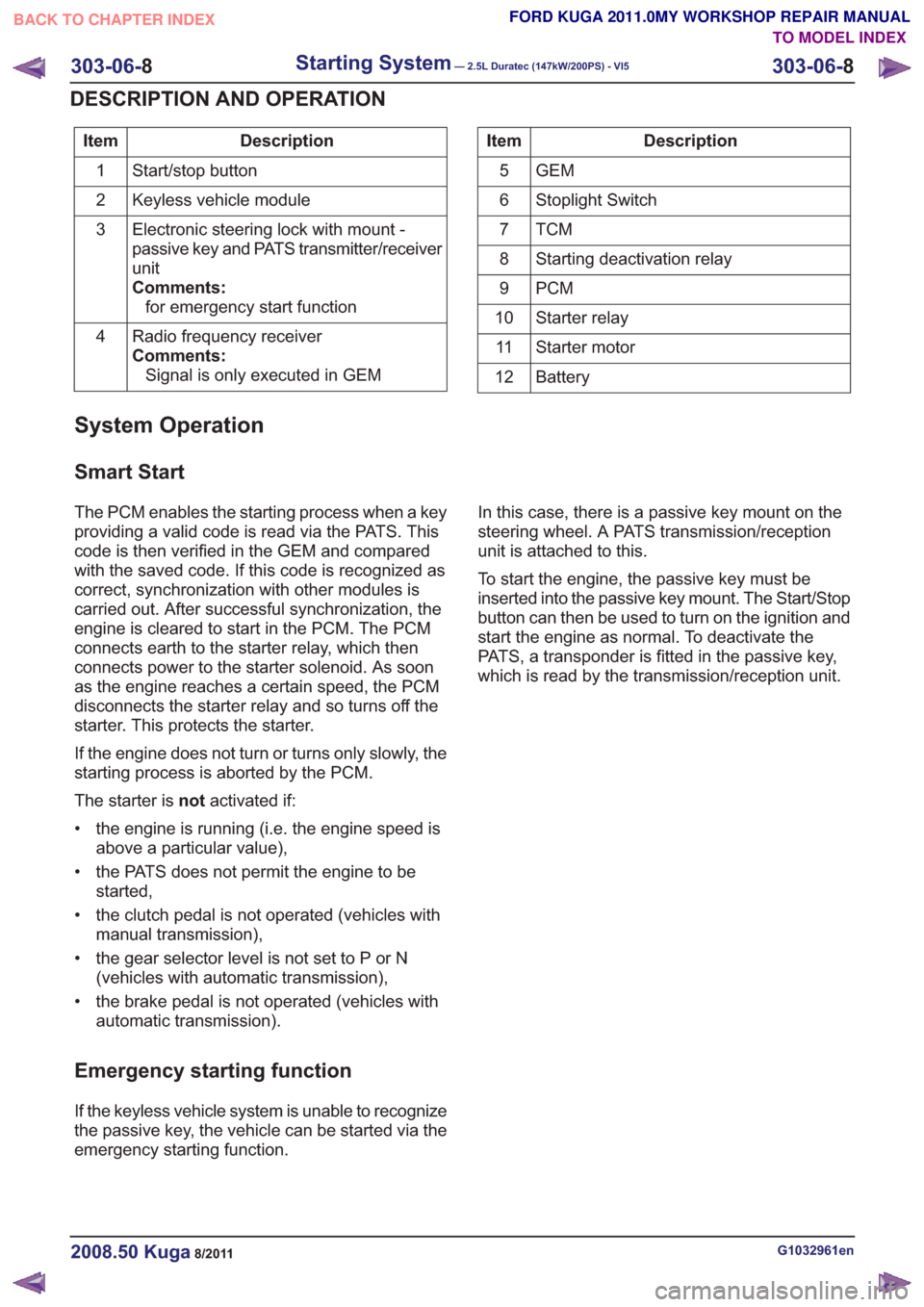
Description
Item
Start/stop button
1
Keyless vehicle module
2
Electronic steering lock with mount -
passive key and PATS transmitter/receiver
unit
Comments:for emergency start function
3
Radio frequency receiver
Comments:Signal is only executed in GEM
4Description
Item
GEM
5
Stoplight Switch
6
TCM7
Starting deactivation relay
8
PCM
9
Starter relay
10
Starter motor
11
Battery
12
System Operation
Smart Start
The PCM enables the starting process when a key
providing a valid code is read via the PATS. This
code is then verified in the GEM and compared
with the saved code. If this code is recognized as
correct, synchronization with other modules is
carried out. After successful synchronization, the
engine is cleared to start in the PCM. The PCM
connects earth to the starter relay, which then
connects power to the starter solenoid. As soon
as the engine reaches a certain speed, the PCM
disconnects the starter relay and so turns off the
starter. This protects the starter.
If the engine does not turn or turns only slowly, the
starting process is aborted by the PCM.
The starter is notactivated if:
• the engine is running (i.e. the engine speed is above a particular value),
• the PATS does not permit the engine to be started,
• the clutch pedal is not operated (vehicles with manual transmission),
• the gear selector level is not set to P or N (vehicles with automatic transmission),
• the brake pedal is not operated (vehicles with automatic transmission).
Emergency starting function
If the keyless vehicle system is unable to recognize
the passive key, the vehicle can be started via the
emergency starting function. In this case, there is a passive key mount on the
steering wheel. A PATS transmission/reception
unit is attached to this.
To start the engine, the passive key must be
inserted into the passive key mount. The Start/Stop
button can then be used to turn on the ignition and
start the engine as normal. To deactivate the
PATS, a transponder is fitted in the passive key,
which is read by the transmission/reception unit.
G1032961en2008.50 Kuga8/2011
303-06-
8
Starting System— 2.5L Duratec (147kW/200PS) - VI5303-06-
8
DESCRIPTION AND OPERATION
TO MODEL INDEX
BACK TO CHAPTER INDEX
FORD KUGA 2011.0MY WORKSHOP REPAIR MANUAL