2011 FORD KUGA ABS Module
[x] Cancel search: ABS ModulePage 71 of 2057

Supplemental Restraint System (SRS) Health and SafetyPrecautions
WARNINGS:
Only qualified technicians are allowed to
work on pyrotechnic components.
INHALED: Exposure to pyrotechnic residue
may cause low blood pressure, severe
headache, irritation of mucous membranes,
fainting, shortness of breath or rapid pulse.
Move a victim to fresh air. Seek immediate
medical attention.
EYE CONTACT: Exposure to unburned
pyrotechnic residue may cause irritation,
burning and etching of the eyes. Flush
immediately with plenty of cold running
water for at least 15 minutes. Seek
immediate medical attention.
EYE CONTACT: Exposure to burned
pyrotechnic residue may cause irritation,
burning and etching of the eyes. Flush
immediately with diluted boric acid
solution. Seek immediate medical
attention.
SKIN CONTACT: Unburned pyrotechnic
residue may be rapidly absorbed through
the skin in toxic quantities. Wash
immediately with plenty of soap and water.
Seek medical attention.
SKIN CONTACT: Burned pyrotechnic
residue may be rapidly absorbed through
the skin in toxic quantities. Wash with
plenty of water. Do not use soap. Seek
medical attention.
SWALLOWED: Unburned pyrotechnic
residue is extremely toxic. If conscious
drink plenty of water then induce vomiting.
Seek immediate medical attention. If
unconscious, or in convulsions do not
attempt to induce vomiting or give
anything by mouth. Seek immediate
medical attention.
SWALLOWED: Burned pyrotechnic residue
is extremely toxic. Drink plenty of water
and seek immediate medical attention.
The deployment key must only be
accessible to authorized personnel.
Make sure that the deployment key remains
removed from the deployment equipment
except during deployment.
If permenantly disabling or enabling the
passenger air bag a new seat belt for
vehicles without or with a passenger air
bag must be installed.
Undeployed pyrotechnic components must
not be deployed in the vehicle.
Pyrotechnic components must be deployed
following local regulations.
Check thoroughly that no loose objects
can be spread during the deployment of
pyrotechnic components.
Pyrotechnic components must be
transported following local regulations.
Never carry out any electrical measurement
on disconnected, undeployed pyrotechnic
components.
Pyrotechnic components must not be
disassembled.
Pyrotechnic components are not
interchangeable between vehicles.
Always carry a live air bag module away
from the body with the air bag or trim cover
pointing upwards.
Live air bag modules must be placed in a
suitable cage when removed from the
vehicle. The air bag or trim cover must be
facing upwards.
Do not install a rearward facing child safety
seat to the passenger seat with an
activated passenger air bag.
CAUTIONS:
Pyrotechnic components must not be
subjected to temperatures higher than
110°C.
Never install aftermarket accessories to
the vehicle on or adjacent to the
supplemental restraint system module.
G548998en2008.50 Kuga8/2011
100-00- 65
General Information
100-00- 65
DESCRIPTION AND OPERATION
TO MODEL INDEX
BACK TO CHAPTER INDEX
FORD KUGA 2011.0MY WORKSHOP REPAIR MANUAL
Page 187 of 2057

Description
Item
Instrument Cluster
1
PCM (powertrain control module)
2
EHPS (electro-hydraulic power steering)
control module
3
Audio unit
4
GEM (generic electronic module)
5
RCM (restraints control module)
6
PATS transceiver
7 Description
Item
Steering wheel lock module
8
Left-hand steering column switch
9
Fuel level sensor
10
Washer water level warning lamp switch
11
Accelerator pedal position sensor
12
CPP (clutch pedal position) sensor/BPP
(brake pedal position) sensor
13
Lighting control switch
14
System Operation
Instrument Cluster
The instrument cluster contains analog displays
as well as warning and control lamps for displaying
the system status; in addiiton, there is an LCD
indicator field for driver information.
The instrument cluster receives the following
signals from the PCM via the high speed CAN
(controller area network) Bus (HS-CAN):
• Vehicle speed – The PCM receives the necessary signalsfrom the ABS (anti-lock brake system) wheel
sensors from the ABS control unit on the
HS-CAN.
• Engine Coolant Temperature
• Engine oil pressure.
• Engine speed
The instrument cluster receives the following
signals from the GEM via the medium speed CAN
Bus (MS-CAN):
• Ambient temperature
• Brake fluid level
• Handbrake control
• Door latch control
• Liftgate latch control
• High beam control
• Headlamp flasher control
• Direction indicator control
The fuel level signal is sent by the two fuel level
sensors in the fuel pumps in the semitrailer tank,
which is wired to the instrument cluster. The
sensors are connected in series, and the total
resistance is determined from the two individual resistors. The instrument cluster converts the raw
fuel level signal into a damped fuel level value.
The odometer shows the total distance travelled
by the vehicle and is based on the same signal as
is processed for the daily mileage counter. The
value is recorded by the instrument cluster and
stored in a protected EEPROM (Electronically
Erasable Programmable Read Only Memory) area.
This area is a memory protected against
manipulation. If the instrument cluster detects an
error in this memory area, e.g. through damage,
the driver is notified with the "Odometer error"
message.
Message center
The message center is operated using the left-hand
switch on the steering column.
The SET/RESET button is activated to select a
submenu and change the settings. If signal tones
have been activated, a short acoustic signal will
sound each time a button is pressed.
By turning the rotary switch, the different menu
displays can be scrolled through or a setting
selected.
In this display, the navigation system can also
display direction and distance information.
In addition, safety and warning messages can be
displayed in this system, such as "Coolant
overheating", "Engine system error" or "Washer
fluid level too low". In addition to a safety message,
a general warning light (red/yellow) lights up.
G1030770en
2008.50 Kuga 8/2011 413-01-4
Instrument Cluster
413-01-4
DESCRIPTION AND OPERATIONTO MODEL INDEX
BACK TO CHAPTER INDEX
FORD KUGA 2011.0MY WORKSHOP REPAIR MANUAL
Page 190 of 2057

Instrument Cluster
Refer to
Wiring Diagrams Section 413-01, for
schematic and connector information. General Equipment
The Ford approved diagnostic tool
Inspection and Verification
1. Verify the customer concern.
2. Visually inspect for obvious signs of mechanical
or electrical damage.
Visual Inspection Chart Electrical
Mechanical
– Fuse(s)
– Wiring harness
– Electricalconnector(s)
– Instrument cluster
– Light emitting diode(s) (LED)(s)
– Engine oil filter
– Engine oil level
–
Engine coolant level
– Oil pressure switch
– Engine coolant level
– Coolant thermostat
– Engine coolant temperature (ECT)
sensor
– Fuel gauge
– Collapsed or damaged fuel tank
– Recirculation hose
– Fuel tank filler pipe/hose
– Indicated fuel level
– Fuel lines
– Fuel tank filler cap
– Fuel filter (external to the fuel tank)
– Fuel tank
– Door adjustment
3. If an obvious cause for an observed or reported concern is found, correct the cause (if possible)
before proceeding to the next step.
4. NOTE: If none of the following warning indicators are operating correctly this may
indicate a concern with the central junction
box (CJB). If only one or two of the following
warning indicators are not operating
correctly this may indicate an instrument
cluster concern. Verify the following warning indicators are
working correctly:
• Charging.
• Turn signals.
• Headlamps.
5. If the cause is not visually evident, verify the symptom and refer to the diagnostic tab within
the Ford approved diagnostic tool.
Configuration of the Instrument Cluster
The instrument cluster is a programmable module,
which must be configured by selecting the
Programmable Module Installation Routine on the
Ford approved diagnostic tool.
NOTE: When the new instrument cluster has been
configured with the odometer value, its
configuration cannot be decreased or matched. A
new configuration will result in an increase in the
displayed odometer value by a minimum of two
units.
NOTE: The odometer value must be recorded from
the original instrument cluster before removal.
If the odometer value cannot be obtained from
the original instrument cluster (display failure)
the customer should supply the approximate
value.
The following features will need to be configured
when a new instrument cluster is installed:
• Anti-lock Brake System (ABS)
• All wheel drive
• Keyless vehicle entry
• Electronic power assisted steering
• Trip computer
• Voice control
• Parking aid
• Belt minder
• Safety belt not fastened
• Right hand drive
• Overspeed warning
• Reverse warning
• Turbocharger boost pressure
• Speed control
• Auxiliary heater
• Suspension control
• Washer fluid sensor G1054964en
2008.50 Kuga 8/2011 413-01-7
Instrument Cluster
413-01-7
DIAGNOSIS AND TESTINGTO MODEL INDEX
BACK TO CHAPTER INDEX
FORD KUGA 2011.0MY WORKSHOP REPAIR MANUAL
Page 207 of 2057
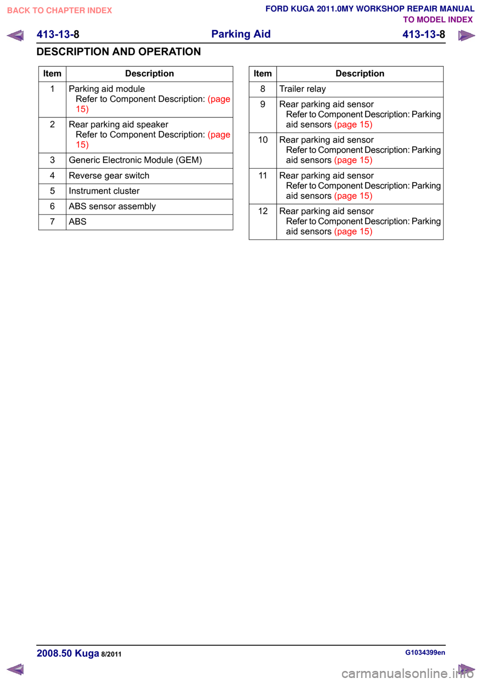
Description
Item
Parking aid moduleRefertoComponentDescription:(page
15)
1
Rear parking aid speakerRefertoComponentDescription:(page
15)
2
Generic Electronic Module (GEM)
3
Reverse gear switch
4
Instrument cluster
5
ABS sensor assembly
6
ABS7 Description
Item
Trailer relay
8
Rear parking aid sensorRefer to Component Description: Parking
aidsensors(page15)
9
Rear parking aid sensorRefer to Component Description: Parking
aidsensors(page15)
10
Rear parking aid sensorRefer to Component Description: Parking
aidsensors(page15)
11
Rear parking aid sensorRefer to Component Description: Parking
aidsensors(page15)
12 G1034399en
2008.50 Kuga 8/2011 413-13-8
Parking Aid
413-13-8
DESCRIPTION AND OPERATIONTO MODEL INDEX
BACK TO CHAPTER INDEX
FORD KUGA 2011.0MY WORKSHOP REPAIR MANUAL
Page 280 of 2057

Direct Current/Alternating Current (DC/AC) Inverter – System
Operation and Component Description
System Diagram Description
Item
DC/AC converterRefer to Component Description: (page
?)
1
AC mains outletRefer to Component Description: (page
?)
2 Description
Item
AC mains outlet switch
3
Battery
4
Ignition relay
5
Keylesss vehicle module
6
System Operation
DC/AC converter
In the rear part of the center console there is an
optional 230 V socket instead of the outlet of the
standard 12 V electrical system.
In this case a DC/AC converter supplies a
continuous power of 150 W at 230 V/50 Hz. It can
also absorb temporary power peaks of up to 300
W when consumers are switched on. For example, an output of 150 W is sufficient to
run laptops, games consoles and mobile phone
chargers.
G1055639en
2008.50 Kuga 8/2011 414-05-4
Voltage Converter/Inverter
414-05-4
DESCRIPTION AND OPERATIONTO MODEL INDEX
BACK TO CHAPTER INDEX
FORD KUGA 2011.0MY WORKSHOP REPAIR MANUAL12456E988853
Page 302 of 2057

Description
Item
In-car entertainment
1
Genetic electronic module (GEM).
2
instrument cluster
3
ABS4
ABS sensor assembly
5
Rear LH mid/bass range speaker
6
Rear RH mid/bass range speaker
7 Description
Item
AUX port
8
Radio remote control.
9
FM/AM antenna
10
Front LH mid/bass speaker
11
Front RH mid/bass speaker
12
Front LH tweeter
13
Front RH tweeter
14 G1055647en
2008.50 Kuga 8/2011 415-01-6
Information and Entertainment System
415-01-6
DESCRIPTION AND OPERATIONTO MODEL INDEX
BACK TO CHAPTER INDEX
FORD KUGA 2011.0MY WORKSHOP REPAIR MANUAL
Page 304 of 2057
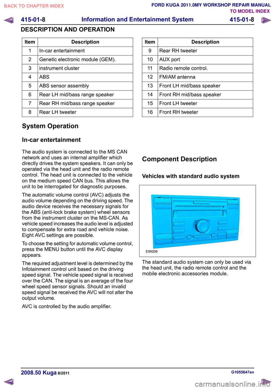
Description
Item
In-car entertainment
1
Genetic electronic module (GEM).
2
instrument cluster
3
ABS4
ABS sensor assembly
5
Rear LH mid/bass range speaker
6
Rear RH mid/bass range speaker
7
Rear LH tweeter
8 Description
Item
Rear RH tweeter
9
AUX port
10
Radio remote control.
11
FM/AM antenna
12
Front LH mid/bass speaker
13
Front RH mid/bass speaker
14
Front LH tweeter
15
Front RH tweeter
16
System Operation
In-car entertainment
The audio system is connected to the MS CAN
network and uses an internal amplifier which
directly drives the system speakers. It can only be
operated via the head unit and the radio remote
control. The head unit is connected to the vehicle
on the medium speed CAN bus. This allows the
unit to be interrogated for diagnostic purposes.
The automatic volume control (AVC) adjusts the
audio volume depending on the driving speed. The
audio device receives the necessary signals for
the ABS (anti-lock brake system) wheel sensors
from the instrument cluster on the MS-CAN. As
vehicle speed increases the audio level is adjusted
to compensate for extra road and vehicle noise.
Eight AVC settings are possible.
To choose the setting for automatic volume control,
press the MENU button until the AVC display
appears.
The required adjustment level is determined by the
Infotainment control unit based on the driving
speed signal. The vehicle speed signal is received
over the CAN. The signal is an average of the four
wheel speed sensor signals. Should an invalid
speed signal be received the AVC will not alter the
output volume.
AVC is controlled by the audio amplifier. Component Description
Vehicles with standard audio system
The standard audio system can only be used via
the head unit, the radio remote control and the
mobile electronic accessories module.
G1055647en
2008.50 Kuga 8/2011 415-01-8
Information and Entertainment System
415-01-8
DESCRIPTION AND OPERATIONTO MODEL INDEX
BACK TO CHAPTER INDEX
FORD KUGA 2011.0MY WORKSHOP REPAIR MANUALE99206
Page 378 of 2057

SECTION 418-00 Module Communications Network
VEHICLE APPLICATION:
2008.50 Kuga
PAGE
CONTENTS
DESCRIPTION AND OPERATION
418-00-2
Communications Network (Component Location)..............................................................
418-00-4
Communications Network (Overview)................................................................................
418-00-5
Communications Network (System Operation and Component Description).....................
418-00-5
System Diagram.................................................................................................................
418-00-6
System Operation...............................................................................................................
418-00-6
General ...........................................................................................................................
418-00-7
Data bus systems...........................................................................................................
418-00-8
Component Description......................................................................................................
418-00-8
ABS .................................................................................................................................
DIAGNOSIS AND TESTING 418-00-9
Communications Network...................................................................................................
418-00-9
Inspection and Checking.................................................................................................... 418-00-1
Module Communications Network
418-00-1
.TO MODEL INDEX
BACK TO CHAPTER INDEX
FORD KUGA 2011.0MY WORKSHOP REPAIR MANUAL