2011 FORD KUGA ABS Module
[x] Cancel search: ABS ModulePage 380 of 2057

Description
Item
Reversing camera module (RVC)
10
Keyless vehicle module (KVM)
11
All-wheel drive control unit
12
RDM - Driver's side
13
RCM (restraints control module)
14
DDM (driver door module)
15
Instrument Cluster
16 Description
Item
High intensity discharge headlamp module
(optional)
17
ABS (anti-lock brake system) module or
electronic stability program module
18
PCM (powertrain control module)
19
The EATC (electronic automatic
temperature control) control module
20
Electrohydraulic power steering module
21 G1072290en
2008.50 Kuga 8/2011 418-00-3
Module Communications Network
418-00-3
DESCRIPTION AND OPERATIONTO MODEL INDEX
BACK TO CHAPTER INDEX
FORD KUGA 2011.0MY WORKSHOP REPAIR MANUAL
Page 383 of 2057

Description
Item
Medium speed CAN (controller area
network) bus (MS-CAN)
A
High speed CAN bus (HS-CAN)
B
LIN (local interconnect network) bus
C
Terminating resistors
Drive
DLC (data link connector)
E
GEMRefer to Component Description: ABS
(page ?)
1
Fuel fired booster heater /programmable
fuel fired booster heater
2
The EATC control module
3
Reversing camera module (RVC)
4
Parking aid module (PAM)
5
DDM6
Front driver's side switch unit
7
Driver's side RDM
8
PDM (Passenger Door Module)
9
Passenger side RDM
10
Audio unit/navigation unit
11
CD changer
12 Description
Item
Navigation system module - vehicles
equipped with DVD navigation system with
touch screen (not communicating with the
diagnostic unit)
13
Navigation system display - vehicles
equipped with DVD navigation system with
touch screen (not communicating with the
diagnostic unit)
14
Control module for electronic auxiliary
equipment (BVC)
15
RCM16
Keyless vehicle module (KVM)
17
Instrument Cluster
18
PCM19
Fuel additive system module.
20
ABS module or electronic stability program
module
21
Yaw rate sensor/lateral acceleration
sensor
22
Headlamp Leveling Module
23
All-wheel drive control unit
24
Electrohydraulic power steering module
25
System Operation
General
In a communications network (data bus system),
various modules of different systems are connected
to one another via one or several lines.
The data bus system is used exclusively for
transmitting data between the connected modules,
as well as between the connected modules and
the Ford diagnostic unit.
In a data bus system, complete data blocks are
transmitted instead of single on/off pulses. In
addition to the actual information, these data blocks
also contain data regarding the address of the
module to be addressed, the size of the data block
and information for monitoring the content of each
individual data block.
Data bus systems offer various advantages: • Simplified data transmission between the
modules due to a standardized protocol
• Fewer sensors and connectors
• Improved diagnostic options
• Lower costs
The DLC is connected to the various data bus
systems and to the power supply via the standard
16-pin GEM. The signal for the module
programming is also transferred via the DLC.
In a data bus system, if there is a break in one or
both lines or there is a short to ground or to voltage,
then communication between the modules and
with the Ford diagnostic unit is disturbed or is no
longer possible at all.
In order to be able to establish communication with
one another, the modules of the individual systems G1030779en
2008.50 Kuga 8/2011 418-00-6
Module Communications Network
418-00-6
DESCRIPTION AND OPERATIONTO MODEL INDEX
BACK TO CHAPTER INDEX
FORD KUGA 2011.0MY WORKSHOP REPAIR MANUAL
Page 384 of 2057

must use the same language. This language is
called a protocol.
At present, Ford uses three different data bus
systems. Depending upon model and equipment
level, all three data bus systems are used. Each
of these data bus systems has its own protocol.
Data bus systems
ISO 9141 bus
The International Organisation for Standardisation
ISO 9141 bus. This consists of a single wire and
is used exclusively for communication between the
modules and the Ford diagnostic unit. The fault
memories of the various modules are read out via
the ISO 9141 bus.
Local Interconnect Network (LIN) bus
The LIN bus is a standard specifically designed for
cost-effective communication between intelligent
sensors and actuators in vehicles. The LIN control
unit subnet is used in every situation where the
bandwidth and versatility of CAN is not needed.
The LIN specification comprises the LIN protocol,
a standard format for describing a complete LIN
and the interface between an LIN and the
application. An LIN comprises a LIN master and
one or more LIN slaves. The LIN utilizes the
master/slave principle for the purpose of bus
access control. This has the significant advantage
that few resources (CPU performance, ROM, RAM)
are required for bus management in the slave
module. The master is implemented in a control
module or a gateway which has the necessary
resources. All communication is initiated by the
master. Consequently, a message always consists
of a header, which is generated by the master, and
a response from the slave. The data transfer rate
is in the region of up to 20 Kbit/s. The LIN master
knows the time sequence of all data which are to
be transmitted. These data are transmitted by the
corresponding LIN slaves (e.g. ultrasonic sensors)
if they are requested to do so by the LIN master.
LIN is a single-wire bus, i.e. the data are
transmitted in the cable via one wire. Usually the
same cable is also used to provide the supply
voltage. The ground connection of the supply
voltage also acts as the ground connection of the
data transmission. An LIN does not use a
terminating resistor.
Controller Area Network (CAN) bus
This consists of two twisted wires and operates
serially (data is transmitted sequentially). It is used
for communication between the modules
themselves and between the modules and the Ford
diagnostic unit. The modules are connected to the
data bus in parallel. New modules can be
incorporated easily, without modifying the other
wiring or modules. The transmitted data is received
by every module connected to the control unit
network (CAN). As each data packet has an
identifier (label), in which the priority of the
message is determined as well as the content
identification, each module can detect whether or
not the data is relevant for its own information
processing. This enables several modules to be
addressed with a particular data packet and
supplied with data simultaneously. For this
purpose, it is ensured that important data (for
example from the ABS) is transmitted first. The
other modules are only able to submit their data to
the data bus after the high-priority messages have
been received.
The advantages of the CAN bus are:
• Minimization of wiring requirements
•
High degree of error protection (fault / fail-proof)
• Robustness
• Good extendibility
• Prioritization of messages
• Inexpensive
• Automatic repetition of faulty messages
• Independent system monitoring and the ability to disconnect faulty modules from the data bus
automatically
Due to the increased number of modules and the
resulting continued increase in data transfer, two
different CAN bus systems are used. Essentially,
they only differ in terms of their data transmission
rates and application areas.
To be able to distinguish between the individual
CAN bus systems, the CAN bus system with the
high transfer speed is called the high speed CAN
bus (HS-CAN). The data are transmitted at a baud
rate of 500 kB/s.
The CAN bus system with the medium transfer
speed is called the medium speed CAN bus
(MS-CAN) and is mainly used for communication
in the comfort electronics or the multimedia system.
The data are transmitted at a baud rate of 125 kB/s.
An interface (gateway) is used to exchange data
between the HS-CAN and the MS-CAN. This
provides the connection between the three CAN
databus systems and is installed in the GEM and
in the electronic instrument cluster. The number of
modules which are connected to the three databus G1030779en
2008.50 Kuga 8/2011 418-00-7
Module Communications Network
418-00-7
DESCRIPTION AND OPERATIONTO MODEL INDEX
BACK TO CHAPTER INDEX
FORD KUGA 2011.0MY WORKSHOP REPAIR MANUAL
Page 385 of 2057
systems depends on the equipment level of the
vehicle.
In order to guarantee a high degree of error
protection, two 120 Ohm terminating resistors are
installed in the CAN. These are integrated in the
first module connected to the CAN and in the last
module connected to the CAN respectively and
are used for suppression as well as the elimination
of voltage peaks. In order to ensure correct
functioning of the data bus system, the modules
must always be connected with an integral
terminating resistor. In order to enable
communication between the modules on the
HS-CAN and the modules on the MS-CAN, one
module is connected to both data bus systems.
The connection of both data bus systems is
designated as a gateway. In this gateway, the
received data is converted to the transmission rate
required for the relevant data bus and is
transmitted. This ensures an optimal distribution
of information between both data bus systems.
Component Description
ABS
The GEM is integrated in the CJB (central junction
box) and cannot be replaced as a separate unit.
G1030779en
2008.50 Kuga 8/2011 418-00-8
Module Communications Network
418-00-8
DESCRIPTION AND OPERATIONTO MODEL INDEX
BACK TO CHAPTER INDEX
FORD KUGA 2011.0MY WORKSHOP REPAIR MANUAL
Page 389 of 2057

Programmable Module Installation
Activation
5.
Install the most up-to-date software version in
IDS.
6. If, before replacing a module, it was not possible
to read out the vehicle-specific data using the
integrated diagnostic system (IDS) (the module
to be replaced does not respond) then, during
programming of the new module, the
vehicle-specific data must be entered manually
via a selection list in IDS or via a code which
can be obtained from the Technical Hotline.
7. In order to program, select the "Install
programmable module" submenu in the "Module
programming" menu tool box and then follow
the instructions.
8. The following modules must be programmed
after replacement:
•
• Anti-lock braking system module (ABS)
• Audio system module (ACM)
• CD player (CDP)
• Driver's door control unit (D-DCU)
• Passenger's door control unit (P-DCU)
• Rear left door control unit (RL-DCU)
• Rear right door control unit (RR-DCU)
• Electrical power steering (EPS)
• Generic Display Module (GDM) (vehicles
with DVD navigation system with
touchscreen)
• Generic electronic module (GEM)
• Headlamp control module (HCM) (vehicles with gas discharge headlamps)
• Instrument cluster (IC)
• Navigation system (NAV) (vehicles with navigation system)
• Parking aid module(PAM)
• Powertrain control module (PCM)
• Restraint control module (RCM)
• Rear entertainment system module (RETM) (vehicles with rear seat entertainment
system)
9. In order to configure the PCM, select the
"Programmable parameters" submenu in the
"Module programming" menu tool box and then
follow the instructions.
10. For vehicles with anti-lock braking system and
electronic stability program, these must also be configured using IDS following replacement of
the lateral acceleration sensor, yaw rate sensor
or pressure sensor. Configuration is performed
in the "Programmable parameters" menu tool
box.
G1158258en
2008.50 Kuga 8/2011 418-01-3
Module Configuration
418-01-3
GENERAL PROCEDURESTO MODEL INDEX
BACK TO CHAPTER INDEX
FORD KUGA 2011.0MY WORKSHOP REPAIR MANUAL
Page 1232 of 2057
Tire Pressure Monitoring System (TPMS) – Overview
Description of operation
The tire pressure monitoring system is able to
detect loss of air in a tire at an early stage and warn
the driver. Because it can only compare the
behavior of the tires with each other, it is not
possible to draw conclusions about the absolute
tire pressure. It is also not possible to monitor the
spare tire pressure. In order for the system to
operate correctly, the tire pressures must be
regularly checked and corrected and the system
subsequently initialized (see below).
The tire pressure monitoring system used here,
depending on the equipment level, is built into the
anti-lock braking system (ABS) as an extra function
and therefore does not have its own sensors.
The ABS module determines the loss of pressure
in the tires by calculation using the wheel speed
sensors of the ABS system. If a tire loses pressure,
its diameter decreases and the speed of the wheel
therefore increases. If the ABS module detects
such a loss in pressure, it sends a signal to the
instrument cluster via the CAN bus and a warning
message is displayed in the driver information
system. The warning threshold depends among
other things on the dimension of the tires being
used, the vehicle operating conditions and the
status at the last initialization. Since neither the
absolute tire pressure nor the position of the tire is
known, after a tire pressure warning the pressure
of all the tires must be checked and the system
re-initialized. If necessary, the cause of the loss of
pressure must be investigated.
Furthermore, regular pressure checks are
necessary. The system must be initialized after a
tire is changed, winter or summer tires fitted, the
pressures corrected or adjusted to suit the vehicle
load. This can be done by the driver using the
driver information system. For further information,
see: Owner’s Manual.
G1001290en2008.50 Kuga8/2011
204-04-5
Wheels and Tires
204-04- 5
DESCRIPTION AND OPERATION
TO MODEL INDEX
BACK TO CHAPTER INDEX
FORD KUGA 2011.0MY WORKSHOP REPAIR MANUAL
Page 1234 of 2057
Engine Speed Sensitive
This means that the vibration occurs at varying
vehicle speeds when a different transmission gear
is selected. It can sometimes be isolated by
increasing or decreasing engine speed with the
transmission in NEUTRAL or by stall testing with
the transmission in gear. If the condition is engine
speed sensitive, the cause is probably not related
to the tires.
If the road test indicates that there is tire whine,
but no shake or vibration, the noise originates with
the contact between the tire and the road surface.A thumping noise usually means that the tire is flat
or has soft spots making a noise as they slap the
roadway. Tire whine can be distinguished from axle
noise. Tire whine remains the same over a range
of speeds.
A complete road test procedure is described in
Section 100-04.
REFER to:
Noise, Vibration and Harshness (NVH)
(100-04 Noise, Vibration and Harshness,
Diagnosis and Testing).
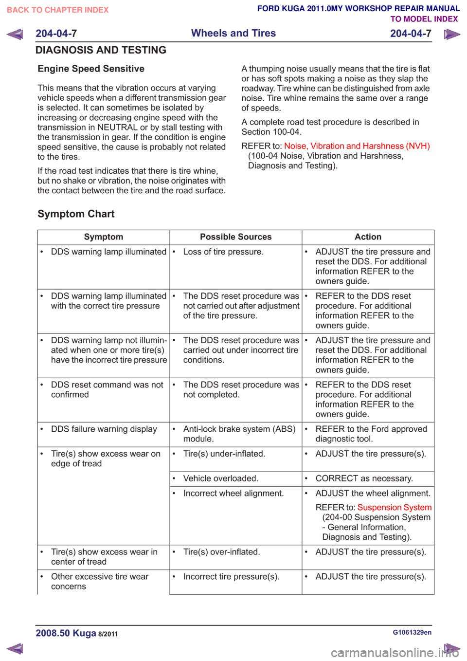
Symptom Chart
Action
Possible Sources
Symptom
• ADJUST the tire pressure andreset the DDS. For additional
information REFER to the
owners guide.
• Loss of tire pressure.
• DDS warning lamp illuminated
• REFER to the DDS resetprocedure. For additional
information REFER to the
owners guide.
• The DDS reset procedure was
not carried out after adjustment
of the tire pressure.
• DDS warning lamp illuminated
with the correct tire pressure
• ADJUST the tire pressure andreset the DDS. For additional
information REFER to the
owners guide.
• The DDS reset procedure was
carried out under incorrect tire
conditions.
• DDS warning lamp not illumin-
ated when one or more tire(s)
have the incorrect tire pressure
• REFER to the DDS resetprocedure. For additional
information REFER to the
owners guide.
• The DDS reset procedure was
not completed.
• DDS reset command was not
confirmed
• REFER to the Ford approveddiagnostic tool.
• Anti-lock brake system (ABS)
module.
• DDS failure warning display
• ADJUST the tire pressure(s).
• Tire(s) under-inflated.
• Tire(s) show excess wear on
edge of tread
• CORRECT as necessary.
• Vehicle overloaded.
• ADJUST the wheel alignment.REFER to: Suspension System
(204-00 Suspension System
- General Information,
Diagnosis and Testing).
• Incorrect wheel alignment.
• ADJUST the tire pressure(s).
• Tire(s) over-inflated.
• Tire(s) show excess wear in
center of tread
• ADJUST the tire pressure(s).
• Incorrect tire pressure(s).
• Other excessive tire wear
concerns
G1061329en2008.50 Kuga8/2011
204-04- 7
Wheels and Tires
204-04- 7
DIAGNOSIS AND TESTING
TO MODEL INDEX
BACK TO CHAPTER INDEX
FORD KUGA 2011.0MY WORKSHOP REPAIR MANUAL
Page 1255 of 2057
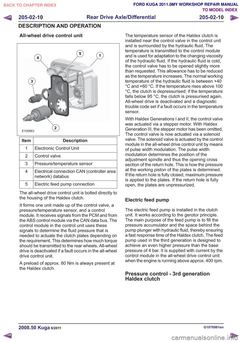
All-wheel drive control unit
E100663
14
3
2
5
Description
Item
Electronic Control Unit
1
Control valve
2
Pressure/temperature sensor
3
Electrical connection CAN (controller area
network) databus
4
Electric feed pump connection
5
The all-wheel drive control unit is bolted directly to
the housing of the Haldex clutch.
It forms one unit made up of the control valve, a
pressure/temperature sensor, and a control
module. It receives signals from the PCM and from
the ABS control module via the CAN data bus. The
control module in the control unit uses these
signals to determine the fluid pressure that is
needed to actuate the clutch plates depending on
the requirement. This determines how much torque
should be transmitted to the rear wheels. All-wheel
drive is deactivated if a fault occurs in the all-wheel
drive control unit.
A preload of approx. 80 Nm is always present at
the Haldex clutch. The temperature sensor of the Haldex clutch is
installed near the control valve in the control unit
and is surrounded by the hydraulic fluid. The
temperature is transmitted to the control module
and is used for adaptation to the changing viscosity
of the hydraulic fluid. If the hydraulic fluid is cold,
the control valve has to be opened slightly more
than requested. This allowance has to be reduced
as the temperature increases. The normal working
temperature of the hydraulic fluid is between +40
°C and +60 °C. If the temperature rises above 100
°C, the clutch is depressurised; if the temperature
falls below 95 °C, the clutch is pressurised again.
All-wheel drive is deactivated and a diagnostic
trouble code set if a fault occurs in the temperature
sensor.
With Haldex Generations I and II, the control valve
was actuated via a stepper motor. With Haldex
Generation III, the stepper motor has been omitted.
The control valve is now actuated via a solenoid
valve. The solenoid valve is actuated by the control
module in the all-wheel drive control unit by means
of pulse width modulation. The pulse width
modulation determines the position of the
adjustment spindle and thus the opening cross
section of the return hole. This is how the pressure
at the working piston of the plates is determined.
If the return hole is fully closed, maximum pressure
is applied to the plates. If the return hole is fully
open, the plates are unpressurized.
Electric feed pump
The electric feed pump is installed in the clutch
unit. It works according to the gerotor principle.
The main purpose of the feed pump is to fill the
pressure accumulator and the space behind the
pump plunger with hydraulic fluid, thereby ensuring
a fast response time of the Haldex clutch. The feed
pump used in the third generation is designed to
achieve an even higher pressure than the base
pressure of 4 bar. It is supplied with current by the
control module in the all-wheel drive control unit
when the engine is running above approx. 400 rpm.
Pressure control - 3rd generation
Haldex clutch
G1076981en2008.50 Kuga8/2011
205-02-
10
Rear Drive Axle/Differential
205-02- 10
DESCRIPTION AND OPERATION
TO MODEL INDEX
BACK TO CHAPTER INDEX
FORD KUGA 2011.0MY WORKSHOP REPAIR MANUAL