Page 5 of 655

SECTION 100-00 General Information
VEHICLE APPLICATION:2011.0 Kuga
PA G E
CONTENTS
DESCRIPTION AND OPERATION
100-00-2
About This Manual ........................................................................\
......................................
100-00-2
How to Use This Manual........................................................................\
............................
100-00-3
Circuit Code ........................................................................\
................................................
100-00-7
Wire Insulation Specification (Temperature) .......................................................................
100-00-7
Wire Color Code ........................................................................\
.........................................
100-00-8
Symbols Glossary ........................................................................\
.......................................
100-00-1
General Information
100-00- 1
.
BACK TO CHAPTER INDEX TO MODEL INDEXFORD KUGA 2011.0MY WIRING DIAGRAMS
Page 6 of 655

About This Manual
How to Use This Manual
This manual is structured into Systems, Groups
and Sections. A System covers a specific portion
of the vehicle. The manual is divided into six
Systems: General Information, Chassis,
Powertrain, Electrical, Body and Paint and General
Wiring Information. Each System contains a
number of Groups that contain a number ofSections relating to specific vehicle systems. Each
Section contains a wiring diagram containing all of
the information relating to the specific vehicle
system. Some Sections contain a number of wiring
diagrams that cover a number of different vehicle
variants. Connector location information and
connector face views are provided through links
within the wiring diagram for each vehicle system.
Example:
Chassis > Brake System > Anti-Lock
Control (System > Group > Section)
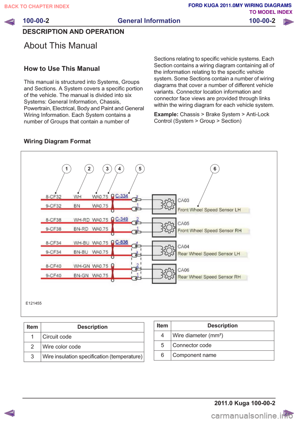
Wiring Diagram Format
123456
E121455
Description
Item
Circuit code
1
Wire color code
2
Wire insulation specification (temperature)
3Description
Item
Wire diameter (mm²)
4
Connector code
5
Component name
6
2011.0 Kuga 100-00-2
100-00- 2
General Information
100-00- 2
DESCRIPTION AND OPERATION
BACK TO CHAPTER INDEX TO MODEL INDEXFORD KUGA 2011.0MY WIRING DIAGRAMS
Page 7 of 655
Description
Position
Electrical potential
1
System
2
Sub-system
3
Function
4 and 5
Some circuit codes also have a suffix. Suffices are used when parts of a circuit are separated with a connector.
Position 1: Potential
Description
Code
GND (ground)
G
Standard voltage
S
Higher than standard voltage
H
Changing or switched
C
Variable signal
V
Lower than standard voltage
L
Return or reference
R
Drain wire
D
Any of the above with a temporary function
Z
Position 2: System
Description
Code
Power convenience
A
Circuit protection
B
Chassis
C
Electrical distribution
D
Diagnostic bus
E
Climate control
F
Information and entertainment
G
Heating
H
Supplemental restraints
J
Windshield wipers and washers
K
Lighting
L
2011.0 Kuga 100-00-3
100-00- 3
General Information
100-00- 3
DESCRIPTION AND OPERATION
Circuit Code
BACK TO CHAPTER INDEX TO MODEL INDEXFORD KUGA 2011.0MY WIRING DIAGRAMS