2011 FORD KUGA power control module
[x] Cancel search: power control modulePage 3 of 655

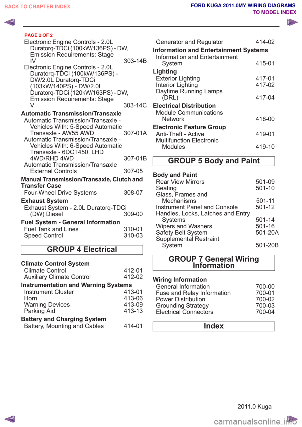
Electronic Engine Controls - 2.0LDuratorq-TDCi (100kW/136PS) - DW,
Emission Requirements: Stage
IV 303-14B
Electronic Engine Controls - 2.0L Duratorq-TDCi (100kW/136PS) -
DW/2.0L Duratorq-TDCi
(103kW/140PS) - DW/2.0L
Duratorq-TDCi (120kW/163PS) - DW,
Emission Requirements: Stage
V 303-14C
Automatic Transmission/Transaxle Automatic Transmission/Transaxle - Vehicles With: 5-Speed Automatic
Transaxle - AW55 AWD 307-01A
Automatic Transmission/Transaxle - Vehicles With: 6-Speed Automatic
Transaxle - 6DCT450, LHD
4WD/RHD 4WD 307-01B
Automatic Transmission/Transaxle External Controls 307-05
Manual Transmission/Transaxle, Clutch and
Transfer Case Four-Wheel Drive Systems 308-07
Exhaust System Exhaust System - 2.0L Duratorq-TDCi (DW) Diesel 309-00
Fuel System - General Information Fuel Tank and Lines 310-01
Speed Control 310-03
GROUP 4 Electrical
Climate Control System
Climate Control 412-01
Auxiliary Climate Control 412-02
Instrumentation and Warning Systems Instrument Cluster 413-01
Horn 413-06
Warning Devices 413-09
Parking Aid 413-13
Battery and Charging System Battery, Mounting and Cables 414-01 Generator and Regulator
414-02
Information and Entertainment Systems Information and Entertainment System 415-01
Lighting Exterior Lighting 417-01
Interior Lighting 417-02
Daytime Running Lamps (DRL) 417-04
Electrical Distribution Module Communications Network 418-00
Electronic Feature Group Anti-Theft - Active 419-01
Multifunction Electronic Modules 419-10
GROUP 5 Body and Paint
Body and Paint
Rear View Mirrors 501-09
Seating 501-10
Glass, Frames and Mechanisms 501-11
Instrument Panel and Console 501-12
Handles, Locks, Latches and Entry Systems 501-14
Wipers and Washers 501-16
Safety Belt System 501-20A
Supplemental Restraint System 501-20B
GROUP 7 General Wiring
Information
Wiring Information
General Information 700-00
Fuse and Relay Information 700-01
Power Distribution 700-02
Grounding Strategy 700-03
Electrical Connectors 700-04
Index
2011.0 Kuga
BACK TO CHAPTER INDEX
TO MODEL INDEXFORD KUGA 2011.0MY WIRING DIAGRAMS
PAGE 2 OF 2
Page 8 of 655

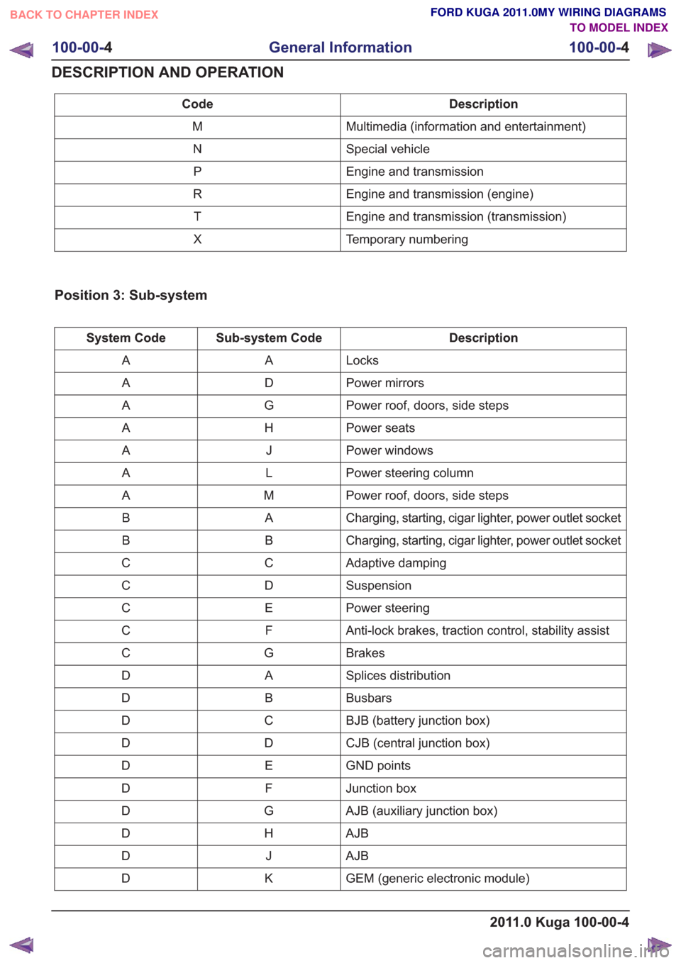
Description
Code
Multimedia (information and entertainment)
M
Special vehicle
N
Engine and transmission
P
Engine and transmission (engine)
R
Engine and transmission (transmission)
T
Temporary numbering
X
Position 3: Sub-system
Description
Sub-system Code
System Code
Locks
A
A
Power mirrors
D
A
Power roof, doors, side steps
G
A
Power seats
H
A
Power windows
J
A
Power steering column
L
A
Power roof, doors, side steps
M
A
Charging, starting, cigar lighter, power outlet socket
A
B
Charging, starting, cigar lighter, power outlet socket
B
B
Adaptive damping
C
C
Suspension
D
C
Power steering
E
C
Anti-lock brakes, traction control, stability assist
F
C
Brakes
G
C
Splices distribution
A
D
Busbars
B
D
BJB (battery junction box)
C
D
CJB (central junction box)
D
D
GND points
E
D
Junction box
F
D
AJB (auxiliary junction box)
G
D
AJB
H
D
AJB
J
D
GEM (generic electronic module)
K
D
2011.0 Kuga 100-00-4
100-00- 4
General Information
100-00- 4
DESCRIPTION AND OPERATION
BACK TO CHAPTER INDEX TO MODEL INDEXFORD KUGA 2011.0MY WIRING DIAGRAMS
Page 10 of 655

Description
Sub-system Code
System Code
Fog lamps
D
L
Headlamps
E
L
Exterior lighting
F
L
Turn signal and hazard lamps
G
L
Instrument cluster and panel illumination
H
L
Instrument panel illumination
K
L
Communication, cellular phone, voice control
C
M
Information and entertainment
D
M
Ambulance
A
N
Police
B
N
Ta x i
C
N
Trailer tow
D
N
Engine cooling
A
P
Speed control
G
P
Connectors
A
R
Destination notes
B
R
Powertrain controller, diode, driver, monitor, pump
D
R
PCM (powertrain control module)
E
R
Motors
G
R
Relays
H
R
Sensors
J
R
Solenoids
L
R
Splices or busbars
N
R
Switches
P
R
Engine ignition
R
R
Powertrain controller, diode, driver, monitor, pump
S
R
Transmission/transaxle, differential, axle
A
T
Automatic transmission
C
T
Transmission/transaxle, differential, axle
D
T
Temporary functions for any sub-system
L
X
2011.0 Kuga 100-00-6
100-00- 6
General Information
100-00- 6
DESCRIPTION AND OPERATION
BACK TO CHAPTER INDEX TO MODEL INDEXFORD KUGA 2011.0MY WIRING DIAGRAMS
Page 30 of 655

SECTION 211-02 Power Steering
VEHICLE APPLICATION:2011.0 Kuga
PA G E
CONTENTS
ELECTRICAL SCHEMATICS
211-02-2
Power Steering — LHD 4WD/LHD FWD ........................................................................\
....
211-02-4
Power Steering — RHD 4WD/RHD FWD ........................................................................\
...
ELECTRICAL CONNECTORS 211-02-6
Power Steering Control (PSC) Module........................................................................\
.......
211-02-6
Power Steering Control (PSC) Module........................................................................\
.......
211-02-6
Power Steering Control (PSC) Module........................................................................\
.......
211-02-6
Steering Angle Sensor ........................................................................\
................................
211-02-7
Steering Angle Sensor ........................................................................\
................................
211-02-1
Power Steering
211-02- 1
.
BACK TO CHAPTER INDEX TO MODEL INDEXFORD KUGA 2011.0MY WIRING DIAGRAMS
Page 32 of 655

E7 RD WK 10.0
2
C793
C793
1
C794
1
10.0WK
BKE73
1
0.50
WA
BN-WH
9-CE10
0.50
WA
WH-VT
8-CE10
7-CE10 YE-VT WA 0.50
2
C792
A2 HS CAN -A3 HS CAN +
IGNITION
A1
B1 B+
B-B2
C15V +
S1 C3
GND C2
MOTOR EHPASM
CAN
CS05
.
3
1
C788
2GND
C1-2
POWER
C1-3
S1 (PWM) OUT
C1-1
CS06
1G
3G
2
C795 G
7-CE10 YE-VT WK 0.50
0.50WK
WH-VT
8-CE10
0.50WK
BN-WH
9-CE10
0.50
WA
GN-BUE7
GND
.Power Steering Control (PSC) ModuleSteering Angle Sensor
211-02-3 Power Steering—LHD 4WD/LHD FWD
2011.0 Kuga (G1223701)
BACK TO CHAPTER INDEX
TO MODEL INDEXFORD KUGA 2011.0MY WIRING DIAGRAMS
Page 34 of 655

E7 RD WK 10.0
2
C793
C793
1
C794
1
10.0WK
BKE7
A2 HS CAN -A3 HS CAN +
IGNITION
A1
B1 B+
B-B2
C15V +
S1 C3
GND C2
MOTOR EHPASM
CAN
CS05
.
GND
C1-2
POWER
C1-3
S1 (PWM) OUT
C1-1
CS06
1G
3G
2
C795 G
0.50
WA
BN-WH
9-CE10A
0.50
WA
WH-VT
8-CE10A
7-CE10A YE-VT WA 0.501
3
C792
2
0.50
WA
GN-BUE7
GND
.Power Steering Control (PSC) ModuleSteering Angle Sensor
211-02-5 Power Steering—RHD 4WD/RHD FWD
2011.0 Kuga (G1223702)
BACK TO CHAPTER INDEX
TO MODEL INDEXFORD KUGA 2011.0MY WIRING DIAGRAMS
Page 35 of 655

Power Steering Control (PSC) Module (G1239825)
23
1
3M5T-14A464-HCD
HARNESS 14K733 TO EHPAS MODULE C792
PIN 2 => 9-CE10 BN-WH 0.50 WA
PIN 1 => 7-CE10 YE-VT 0.50 WA
PIN 3 => 8-CE10 WH-VT 0.50 WA
0.50
WABN-WH9-CE10A0.50WAWH-VT8-CE10A
0.50WAYE-VT7-CE10A
Power Steering Control (PSC) Module (G1239826)
1
2
5M5T-14A464-NBD
HARNESS 14K733 TO EHPAS C793 10.0
WKRD30-CE7
10.0WKBK31-CE7
Power Steering Control (PSC) Module (G1239827)
23
1
3M5T-14A464-GCC
HARNESS 14K733 TO EHPAS C794 0.50
WABU-RD5-EC7W0.50WAGY-RD4-EC7W
0.50WAGN-BU15-CE7
Steering Angle Sensor (G1226604)
1234
3M5T-14489-BDA
HARNESS 14401 TO STEERING ANGEL SENSOR C784 0.35
WABN-BU9-CE80.35WAGY-VT10-CE80.35WAWH-BU8-CE80.35WAYE-BU7-CE8
201
1.0 Kuga
211-02-6
Power Steering
211-02- 6
.
BACK TO CHAPTER INDEX TO MODEL INDEXFORD KUGA 2011.0MY WIRING DIAGRAMS
Page 86 of 655

SECTION 303-14A Electronic Engine Controls— 2.5L Duratec
(147kW/200PS) - VI5
VEHICLE APPLICATION: 2011.0 Kuga
PA G E
CONTENTS
ELECTRICAL SCHEMATICS
303-14A-2
Engine Control — Vehicles With: 6-Speed Manual Transaxle - M66 AWD, LHD 4WD ......
303-14A-8
Engine Control — Vehicles With: 5-Speed Automatic Transaxle - AW55 AWD, LHD 4WD .
303-14A-14
Engine Control — Vehicles With: 6-Speed Manual Transaxle - M66 AWD, RHD 4WD .....
303-14A-20
Engine Control — Vehicles With: 5-Speed Automatic Transaxle - AW55 AWD, RHD 4WD .
ELECTRICAL CONNECTORS 303-14A-26
Accelerator Pedal Position (APP) Sensor ........................................................................\
..
303-14A-26
Brake Pedal Position (BPP) Switch ........................................................................\
............
303-14A-26
Catalyst Monitor Sensor ........................................................................\
.............................
303-14A-26
Clutch Pedal Position (CPP) Switch ........................................................................\
...........
303-14A-27
Clutch Pedal Position (CPP) Switch ........................................................................\
...........
303-14A-27
Clutch Pedal Position (CPP) Switch ........................................................................\
...........
303-14A-27
Crankshaft Position (CKP) Sensor ........................................................................\
.............
303-14A-27
Engine Coolant Temperature (ECT) Sensor .......................................................................
303-14A-28
Exhaust Camshaft Position (CMP) Sensor ........................................................................\
.
303-14A-28
Exhaust Variable Valve Timing (VVT) Oil Control Solenoid ................................................
303-14A-28
Fuel Rail Pressure (FRP) Sensor ........................................................................\
...............
303-14A-28
Fuel Rail Temperature Sensor ........................................................................\
....................
303-14A-29
Fuel Rail Pressure and Temperature Sensor .....................................................................
303-14A-29
Heated Oxygen Sensor (HO2S) ........................................................................\
.................
303-14A-29
Intake Camshaft Position (CMP) Sensor ........................................................................\
....
303-14A-29
Intake Variable Valve Timing (VVT) Oil Control Solenoid ...................................................
303-14A-30
Knock Sensor (KS) ........................................................................\
.....................................
303-14A-30
Manifold Absolute Pressure and Temperature (MAPT) Sensor ..........................................
303-14A-30
Mass Air Flow (MAF) Sensor ........................................................................\
......................
303-14A-31
Powertrain Control Module (PCM) ........................................................................\
..............
303-14A-32
Powertrain Control Module (PCM) ........................................................................\
..............
303-14A-1
Electronic Engine Controls— 2.5L Duratec (147kW/200PS) - VI5303-14A-
1
.
BACK TO CHAPTER INDEX TO MODEL INDEXFORD KUGA 2011.0MY WIRING DIAGRAMS