Page 49 of 100
™
System Operation
• The screen is located in the overhead compartment console. To lower the screen,press the release button located in the center of the console re")
VIDEO ENTERTAINMENT SYSTEM (VES)™
System Operation
• The screen is located in the overhead compartment console. To lower the screen,press the release button located in the center of the console rear of the screen.
• The system may be controlled by the front seat occupants using either the radio or DVD player controls, or by the rear seat occupants using the remote control.
• The video screen displays information in a split screen format. The left side of the screen is referred to as Channel 1 and the right side of the screen is referred to as
Channel 2. All modes except video modes are displayed in a split screen format.
• To use the headphones, press the power button located on the right ear cup. Select the channel on the headphones (1 or 2) which corresponds to the channel selected
on the desired video screen.
• To receive VES™ audio through the vehicle's sound system, press the VES™ soft-key on the radio's touch-screen.
Operation Of The Touch-Screen Radio/DVD Player
• To view a DVD press the OPEN/CLOSE or LOAD hard-key on the touch-screen radioand insert the disc or insert the disc into the optional DVD player. Playback will
begin automatically after the DVD is recognized by the disc drive. If playback does
not begin automatically when the disc is inserted into the DVD player press the
PLAY button. If playback does not begin automatically after the disc is inserted
into the touch-screen radio follow these steps:
• Press the MENU hard-key, then touch the Rear VES™ soft-key. If a chapter list
appears on the right side of the screen, touch the HIDE LIST soft-key to display
the Rear VES™ control screen.
• Touch the 1 soft key to select an audio channel, then touch the DISC soft-key in the MEDIA column.
Operation Of The Remote Control
• The remote control operates similarly to any DVD remote you may have used beforeand allows the rear seat passengers to change stations, tracks, discs and
audio/video modes.
• The remote control is designed to control either channel by using the selector switch located on the right side of the remote.
• Connect the video game or other external media devises to the AUX jacks following the color coding for the VES™ jacks.
• Pressing the power button will turn the VES™ system ON/OFF.
• Pressing the mode button causes the MODE SELECTION menu to appear on the VES™ screen. Use the remote control arrow buttons to scroll through the available
modes, and then press ENTER to select the desired mode.
Auxiliary Audio/Video Input Jacks
• The AUX jacks are located on the drivers side rear trim panel behind the slidingdoor.
ELECTRONICS
47
Page 50 of 100

• Connect the video game or other external media devises to the AUX jacks followingthe color coding for the VES™ jacks.
• Using either the touch-screen radio or remote control, select AUX from the REAR VES™ CONTROL or the MODE SELECTION screen.
• Refer to the Uconnect™ Multimedia – Video Entertainment System (VES)™ section in the Uconnect™ User's Manual on the DVD for further details.
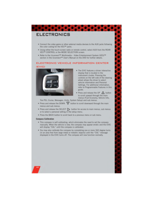
ELECTRONIC VEHICLE INFORMATION CENTER
(EVIC)
• The EVIC features a driver interactivedisplay that is located in the
instrument cluster. Pressing the
controls on the left side of the steering
wheel allows the driver to select
vehicle information and Personal
Settings. For additional information,
refer to Programmable Features in this
guide.
• Press and release the UP
button
to scroll upward through the main
menus (Fuel Economy, Vehicle Info,
Tire PSI, Cruise, Messages, Units, System Setup) and sub menus.
• Press and release the DOWN
button to scroll downward through the main
menus and sub menus.
• Press and release the SELECT
button for access to main menus, sub menus
or to select a personal setting in the setup menu.
• Press the BACK button to scroll back to a previous menu or sub menu.
Compass Calibration
• This compass is self-calibrating, which eliminates the need to set the compass manually. When the vehicle is new, the compass may appear erratic and the EVIC
will display “CAL” until the compass is calibrated.
• You may also calibrate the compass by completing one or more 360 degree turns (in an area free from large metal or metallic objects) until the “CAL” message
displayed in the EVIC turns off. The compass will now function normally.
ELECTRONICS
48
Page 51 of 100
 – If Equipped
• The EVIC can be used to program the following Personal Settings. Press andrelease the MENU button until Personal")
PROGRAMMABLE FEATURES
Electronic Vehicle Information Center (EVIC) – If Equipped
• The EVIC can be used to program the following Personal Settings. Press andrelease the MENU button until Personal Settings displays, then press the DOWN
button
to scroll through the settings. Press the SELECT buttonto
change the setting.
• Language • Turn Headlamps On With Remote Key
Unlock
• Lock Door Automatically at 15 mph (24 km/h) • Confirmation of Voice Commands
• Auto Unlock On Exit • Illuminated Approach
• Remote Unlock Driver's Door 1st • Hill Start Assist (HSA)
• Sound Horn With Remote Key Lock • Display Units In
• Flash Lights With Remote Key Lock • Automatic Compass Calibration
• Delay Turning Headlights Off • Compass Variance
• Delay Power Off to Accessories until Exit • To Set the Variance
Key Fob Programmable Features
• The following features may also be programmed by using the Key Fob transmitter
or the ignition switch and driver's door lock switch.
NOTE: Pressing the LOCK button while you are inside the vehicle will activate the
Vehicle Security Alarm. Opening a door with the Vehicle Security Alarm activated will
cause the alarm to sound. Press the UNLOCK button to deactivate the Vehicle Security
Alarm.
Unlock On First Press• To unlock either the driver's side, or all doors, on the first press of the UNLOCK button:
• Press and hold the LOCK button for at least 4 seconds, but no longer than
10 seconds. Then, press and hold the UNLOCK button while still holding the
LOCK button.
• Release both buttons at the same time.
ELECTRONICS
49
Page 52 of 100

Auto Unlock Doors On Exit• To have all of the vehicle doors unlock when any door is opened: • Enter your vehicle and close all the doors.
• Cycle the ignition switch between LOCK and ON and then back to LOCK fourtimes, ending up in the LOCK position (do not start the engine).
• Press the power door UNLOCK switch to unlock the doors. A single chime will indicate that programming is complete.
Auto Door Lock • To have the doors lock automatically when the vehicle’s speed exceeds 15 mph (24 km/h):
• Enter your vehicle and close all the doors.
• Cycle the ignition switch between LOCK and ON and then back to LOCK four
times, ending up in the LOCK position (do not start the engine).
• Press the power door LOCK switch to lock the doors. A single chime will indicate that programming is complete.
Sound Horn With Lock • To turn the horn chirp on or off when the doors are locked: • Press the LOCK button for at least 4 seconds, but no longer than 10 seconds.Then, press the PANIC button while still holding the LOCK button.
• Release both buttons at the same time.
Flashing Lights With Lock • The turn signal lights flashing, when the doors are locked or unlocked, feature can be turned on or off. To turn this feature on or off:
• Press and hold the UNLOCK button for at least 4 seconds, but no longer than
10 seconds. Then, press and hold the LOCK button while still holding the
UNLOCK button.
• Release both buttons at the same time.
ELECTRONICS
50
Page 53 of 100

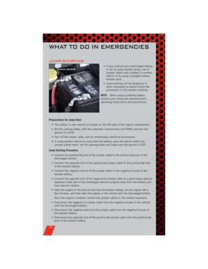
Programming HomeLink®
Begin Programming• The HomeLink®buttons are located in
the overhead console.
• Erase all channels before you begin programming by")
UNIVERSAL GARAGE DOOR OPENER
(HomeLink®)
Programming HomeLink®
Begin Programming• The HomeLink®buttons are located in
the overhead console.
• Erase all channels before you begin programming by holding the two
outside buttons for up to 20 seconds
until the red indicator flashes.
• Park your vehicle outside of the garage and turn the ignition switch to the
ON/RUN position.
• Place the hand-held transmitter 1 to 3 in (3 to 8 cm) from the HomeLink
®buttons
while keeping the indicator light in view.
• Simultaneously, press and hold both the chosen HomeLink
®button and the
hand-held transmitter button until the HomeLink®indicator flash rate changes
from a slow to a rapidly blinking light, then release both the HomeLink®and the
hand-held transmitter buttons. This may take up to 30 seconds, or longer in rare
cases.
• Press and hold the just-programmed HomeLink
®button; if the indicator light stays
on constantly, programming is complete and the garage door should open.
NOTE:
• Only use this transceiver with a garage door opener that has a “stop and reverse” feature as required by Federal safety standards. This includes most garage door
opener models manufactured after 1982. Do not use a garage door opener without
these safety features. Call toll-free 1–800–355–3515 or, on the Internet, at
www.HomeLink.com for safety information or assistance.
• If you are having difficulty programming your HomeLink
®and your garage door
opener was manufactured after 1995, you may have a rolling code. Follow the steps
below for Programming A Rolling Code System.
Programming A Rolling Code System • At the garage door opener motor (in the garage), locate the “learn” or “programming” button. This can usually be found where the hanging antenna wire
is attached to the garage door opener motor (it is NOT the button normally used to
open and close the door).
ELECTRONICS
51
Page 54 of 100

• Firmly press and release the “learn” or “programming” button. The name and colorof the button may vary by manufacturer. Within 30 seconds, return to the vehicle
and press the programmed HomeLink
®button twice (holding the button for two
seconds each time). If the device is plugged in and activates, programming is
complete.
• If the device does not activate, press the button a third time (for two seconds) to complete the programming.
Using HomeLink
®
• To operate, simply press and release the programmed HomeLink®button and the
programmed device will operate.
• Refer to your Owner’s Manual on the DVD for further details. If you have any problems programming HomeLink
®, or require assistance, please call toll-free
1–800–355–3515 or, on the Internet, at www.HomeLink.com.
WARNING!
• Your motorized door or gate will open and close while you are programming the universal transceiver. Do not program the transceiver if people or pets are
in the path of the door or gate.
• Do not run your vehicle in a closed garage or confined area while programming the transceiver. Exhaust gas from your vehicle contains Carbon
Monoxide (CO) which is odorless and colorless. Carbon Monoxide is
poisonous when inhaled and can cause you and others to be severely injured
or killed.
ELECTRONICS
52
Page 55 of 100

POWER INVERTER
• There is a 115 Volt, 150 Watt powerinverter outlet located on the left rear
trim panel immediately behind the
second row left passenger seat. This
outlet can power cellular phones,
electronics and other low power
devices requiring power up to 150
Watts.
• Press the switch located in the center of the instrument panel to turn the
power to the outlet on.
• Press the switch again to turn the power off.
• The status indicator of the AC power inverter indicates whether the inverter is producing AC power.
NOTE: The power inverter is designed with built-in overload protection. If the power
rating of 150 Watts is exceeded, the power inverter will automatically shut down. Once
the electrical device has been removed from the outlet, the inverter should
automatically reset. If the power rating exceeds approximately 170 Watts, the power
inverter may have to be reset manually. To reset the inverter manually, unplug the
device and plug it in again. To avoid overloading the circuit, check the power ratings on
electrical devices prior to using the inverter.
WARNING!
To Avoid Serious Injury or Death: Do not use a three-prong adaptor. Do not
insert any objects into the receptacles. Do not touch with wet hands. Close the
lid when not in use. If this outlet is mishandled, it may cause an electric shock
and failure.
ELECTRONICS
53
Page 56 of 100
POWER OUTLETS
• There are four 12 Volt power outlets inyour vehicle.
• Two are located on the lower instrument panel, next to the open
storage bin. The upper power outlet is
controlled by the ignition switch and
the lower power outlet is connected
directly to the battery.
• One is located in the removable floor console and is also connected directly
to the battery.
• One is located in the rear quarter panel near the liftgate. This outlet is also controlled by the ignition switch.
NOTE:
• Do not exceed the maximum power of 160 Watts (13 Amps) at 12 Volts. If the 160 Watt (13 Amp) power rating is exceeded, the fuse protecting the system will need to
be replaced.
• All accessories connected to the “battery” powered outlets should be removed or turned off when the vehicle is not in use to protect the battery against discharge.
ELECTRONICS
54