2011 CHEVROLET SUBURBAN lock
[x] Cancel search: lockPage 353 of 542

Black plate (65,1)Chevrolet Tahoe/Suburban Owner Manual - 2011
Driving and Operating 9-65
When SBZA is disabled for any
reason other than the driver turning
it off, the driver will not be able to
turn SBZA back on using the DIC.
The SIDE BLIND ZONE ALERT ON
option will not be selectable if the
conditions for normal system
operation are not met. Until normal
operating conditions for SBZA are
met, you should not rely upon SBZA
while driving.
SBZA Error Messages
The following messages may
appear in the DIC:
SIDE BLIND ZONE ALERT
SYSTEM OFF:This message
indicates that the driver has turned
the system off. SIDE BLIND ZONE SYS.
UNAVAILABLE:
This message
indicates that the SBZA system is
disabled either because the sensor
is blocked and cannot detect
vehicles in your blind zone, or the
vehicle is passing through an open
field of view area, such as the
desert, where there is insufficient
data for operation. The sensor may
be blocked by mud, dirt, snow, ice,
slush, or even heavy rainstorms.
This message may also activate
during heavy rain or due to road
spray. The vehicle does not need
service. For cleaning, see “Washing
the Vehicle” underExterior Care on
page 10‑98.
SERVICE SIDE BLIND ZONE
ALERT SYSTEM: If this message
appears, both SBZA displays will
remain on indicating there is a
problem with the SBZA system.
If these displays remain on after
continued driving, the system needs
service. Take the vehicle to your
dealer.FCC Information
See Radio Frequency Statement on
page 13‑18 for information
regarding Part 15 of the Federal
Communications Commission (FCC)
rules and Industry Canada
Standards RSS-210/220/310.
Frequency of operation:
24.05GHz –24.25GHz
Field Strength: Not greater than
2.5V/m peak (0.25V/m average) at a
distance of 3m
The manufacturer is not responsible
for any radio or TV interference
caused by unauthorized
modifications to this equipment.
Such modifications could void the
user's authority to operate the
equipment.
Page 364 of 542
Black plate (76,1)Chevrolet Tahoe/Suburban Owner Manual - 2011
9-76 Driving and Operating
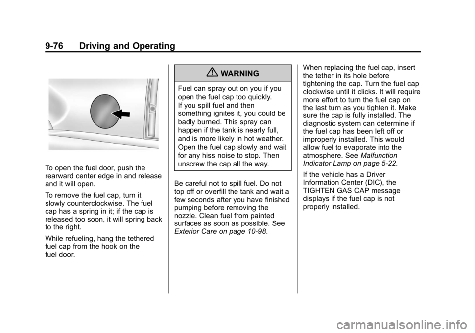
To open the fuel door, push the
rearward center edge in and release
and it will open.
To remove the fuel cap, turn it
slowly counterclockwise. The fuel
cap has a spring in it; if the cap is
released too soon, it will spring back
to the right.
While refueling, hang the tethered
fuel cap from the hook on the
fuel door.
{WARNING
Fuel can spray out on you if you
open the fuel cap too quickly.
If you spill fuel and then
something ignites it, you could be
badly burned. This spray can
happen if the tank is nearly full,
and is more likely in hot weather.
Open the fuel cap slowly and wait
for any hiss noise to stop. Then
unscrew the cap all the way.
Be careful not to spill fuel. Do not
top off or overfill the tank and wait a
few seconds after you have finished
pumping before removing the
nozzle. Clean fuel from painted
surfaces as soon as possible. See
Exterior Care on page 10‑98. When replacing the fuel cap, insert
the tether in its hole before
tightening the cap. Turn the fuel cap
clockwise until it clicks. It will require
more effort to turn the fuel cap on
the last turn as you tighten it. Make
sure the cap is fully installed. The
diagnostic system can determine if
the fuel cap has been left off or
improperly installed. This would
allow fuel to evaporate into the
atmosphere. See
Malfunction
Indicator Lamp on page 5‑22.
If the vehicle has a Driver
Information Center (DIC), the
TIGHTEN GAS CAP message
displays if the fuel cap is not
properly installed.
Page 379 of 542
Black plate (91,1)Chevrolet Tahoe/Suburban Owner Manual - 2011
Driving and Operating 9-91
See“Weight of the Trailer” earlier in
the section. Tow/Haul is most useful
under the following driving
conditions:
.When pulling a heavy trailer or a
large or heavy load through
rolling terrain.
.When pulling a heavy trailer or a
large or heavy load in stop and
go traffic.
.When pulling a heavy trailer or a
large or heavy load in busy
parking lots where improved low
speed control of the vehicle is
desired.
Operating the vehicle in
Tow/Haul when lightly loaded or
with no trailer at all will not cause
damage. However, there is no
benefit to the selection of Tow/Haul
when the vehicle is unloaded. Such
a selection when unloaded may
result in unpleasant engine and
transmission driving characteristics
and reduced fuel economy. Tow/ Haul is recommended only when
pulling a heavy trailer or a large or
heavy load.
Integrated Trailer Brake
Control System
The vehicle may have an Integrated
Trailer Brake Control (ITBC) system
for electric trailer brakes.
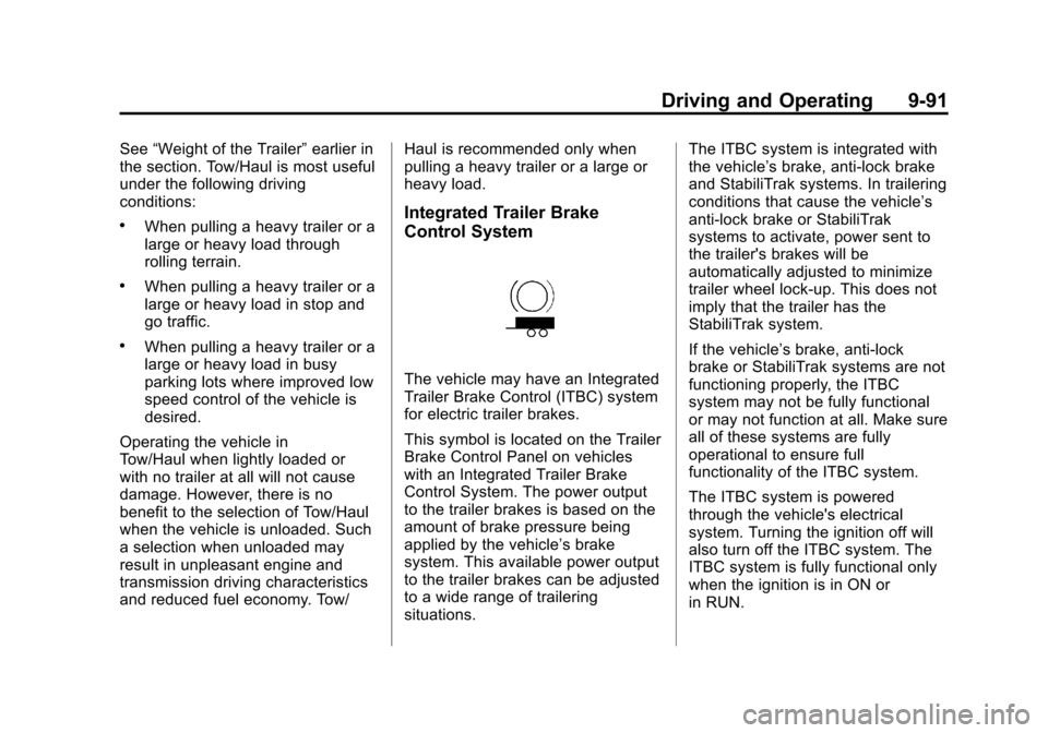
This symbol is located on the Trailer
Brake Control Panel on vehicles
with an Integrated Trailer Brake
Control System. The power output
to the trailer brakes is based on the
amount of brake pressure being
applied by the vehicle’s brake
system. This available power output
to the trailer brakes can be adjusted
to a wide range of trailering
situations.The ITBC system is integrated with
the vehicle’
s brake, anti‐lock brake
and StabiliTrak systems. In trailering
conditions that cause the vehicle’s
anti‐lock brake or StabiliTrak
systems to activate, power sent to
the trailer's brakes will be
automatically adjusted to minimize
trailer wheel lock-up. This does not
imply that the trailer has the
StabiliTrak system.
If the vehicle’s brake, anti‐lock
brake or StabiliTrak systems are not
functioning properly, the ITBC
system may not be fully functional
or may not function at all. Make sure
all of these systems are fully
operational to ensure full
functionality of the ITBC system.
The ITBC system is powered
through the vehicle's electrical
system. Turning the ignition off will
also turn off the ITBC system. The
ITBC system is fully functional only
when the ignition is in ON or
in RUN.
Page 382 of 542
Black plate (94,1)Chevrolet Tahoe/Suburban Owner Manual - 2011
9-94 Driving and Operating
0.0 (zero) gain is the factory default
setting. To properly adjust trailer
gain, see the Trailer Gain
Adjustment Procedure later in this
section.
TRAILER OUTPUT–This is
displayed any time a trailer with
electric brakes is connected. Output
to the electric brakes is based on
the amount of vehicle braking
present and relative to the Trailer
Gain setting. Output is displayed
from 0 to 10 bars for each gain
setting.
The Trailer Output will indicate
“- - - - - -“ on the Trailer Brake
Display Page whenever the
following occur:
.No trailer is connected.
.A trailer without electric brakes
is connected (no DIC message
is displayed).
.A trailer with electric brakes
has become disconnected
(a CHECK TRAILER WIRING
message will also be displayed
on the DIC).
.There is a fault present in the
wiring to the electric trailer
brakes (a CHECK TRAILER
WIRING message will also be
displayed on the DIC).
.There is a fault in the ITBC
system (a SERVICE TRAILER
BRAKE SYSTEM message will
also be displayed in the DIC).
Manual Trailer Brake Apply
The Manual Trailer Brake Apply
Lever is located on the Trailer Brake
Control Panel and is used to apply
the trailer ’s electric brakes
independent of the vehicle’s brakes.
This lever is used in the Trailer Gain
Adjustment Procedure to properly
adjust the power output to the trailer
brakes. Sliding the lever to the left
will apply only the trailer brakes.
The power output to the trailer is
indicated in the Trailer Brake Display Page in the DIC. If the
vehicle’s service brakes are applied
while using the Manual Trailer Brake
Apply Lever, the trailer output power
will be the greater of the two.
The trailer and the vehicle's brake
lamps will come on when either
vehicle braking or manual trailer
brakes are applied.
Trailer Gain Adjustment Procedure
Trailer Gain should be set for a
specific trailering condition and must
be adjusted any time vehicle
loading, trailer loading or road
surface conditions change.
Setting the Trailer Gain properly is
needed for the best trailer stopping
performance. A trailer that is
over-gained may result in locked
trailer brakes. A trailer that is
under-gained may result in not
enough trailer braking. Both of these
conditions may result in poorer
stopping and stability of the vehicle
and trailer.
Page 383 of 542

Black plate (95,1)Chevrolet Tahoe/Suburban Owner Manual - 2011
Driving and Operating 9-95
Use the following procedure to
correctly adjust Trailer Gain for each
towing condition:
1. Make sure the trailer brakes arein proper working condition.
2. Connect a properly loaded trailer to the vehicle and make all
necessary mechanical and
electrical connections. See
Vehicle Load Limits on
page 9‑23 for more information.
3. After the electrical connection is made to a trailer equipped with
electric brakes:
.A TRAILER CONNECTED
message will be briefly
displayed on the DIC
display.
.The Trailer Brake Display
Page will appear on the
DIC showing TRAILER
GAIN and TRAILER
OUTPUT.
.In the Trailer Output display
on the DIC, “- - - - - -“will
disappear if there is no
error present. Connecting a
trailer without electric
brakes will not clear the six
dashed lines.
4. Adjust the Trailer Gain by using the gain adjustment (+ / -)
buttons on the Trailer Brake
Control Panel.
5. Drive the vehicle with the trailer attached on a level road surface
representative of the towing
condition and free of traffic at
about 32 to 40 km/h (20 to
25 mph) and fully apply the
Manual Trailer Brake Apply
lever.
Adjusting trailer gain at speeds
lower than 32 to 40 km/h (20 to
25 mph) may result in an
incorrect gain setting. 6. Adjust the Trailer Gain to just
below the point of trailer wheel
lock-up, indicated by trailer
wheel squeal or tire smoke when
a trailer wheel locks.
Trailer wheel lock-up may not
occur if towing a heavily loaded
trailer. In this case, adjust the
Trailer Gain to the highest
allowable setting for the towing
condition.
7. Re-adjust Trailer Gain any time vehicle loading, trailer loading or
road surface conditions change
or if trailer wheel lock-up is
noticed at any time while towing
Page 391 of 542
Black plate (1,1)Chevrolet Tahoe/Suburban Owner Manual - 2011
Vehicle Care 10-1
Vehicle Care
General Information
General Information . . . . . . . . . . 10-2
California Proposition65 Warning . . . . . . . . . . . . . . . . . 10-3
California Perchlorate Materials Requirements . . . . 10-3
Accessories and Modifications . . . . . . . . . . . . . . . 10-3
Vehicle Checks
Doing Your OwnService Work . . . . . . . . . . . . . . . 10-4
Hood . . . . . . . . . . . . . . . . . . . . . . . . 10-5
Engine Compartment Overview . . . . . . . . . . . . . . . . . . . 10-6
Engine Oil . . . . . . . . . . . . . . . . . . . 10-7
Engine Oil Life System . . . . . 10-11
Automatic Transmission Fluid . . . . . . . . . . . . . . . . . . . . . . 10-12
Engine Air Cleaner/Filter . . . . 10-15
Cooling System . . . . . . . . . . . . 10-16
Engine Coolant . . . . . . . . . . . . . 10-17
Engine Overheating . . . . . . . . 10-21 Overheated Engine
Protection
Operating Mode . . . . . . . . . . . 10-23
Engine Fan . . . . . . . . . . . . . . . . . 10-23
Power Steering Fluid . . . . . . . 10-24
Washer Fluid . . . . . . . . . . . . . . . 10-25
Brakes . . . . . . . . . . . . . . . . . . . . . 10-26
Brake Fluid . . . . . . . . . . . . . . . . . 10-27
Battery . . . . . . . . . . . . . . . . . . . . . 10-29
Four-Wheel Drive . . . . . . . . . . . 10-29
Front Axle . . . . . . . . . . . . . . . . . . 10-30
Rear Axle . . . . . . . . . . . . . . . . . . 10-31
Starter Switch Check . . . . . . . 10-32
Automatic Transmission Shift Lock Control Function
Check . . . . . . . . . . . . . . . . . . . . . 10-33
Ignition Transmission Lock Check . . . . . . . . . . . . . . . . . . . . . 10-33
Park Brake and P (Park) Mechanism Check . . . . . . . . 10-34
Wiper Blade Replacement . . . . . . . . . . . . . . 10-34
Glass Replacement . . . . . . . . 10-35
Headlamp Aiming
Headlamp Aiming . . . . . . . . . . 10-36
Bulb Replacement
Bulb Replacement . . . . . . . . . . 10-38
Halogen Bulbs . . . . . . . . . . . . . . 10-38
Taillamps, Turn Signal, Stoplamps, and Back-Up
Lamps . . . . . . . . . . . . . . . . . . . . 10-38
License Plate Lamp . . . . . . . . 10-39
Replacement Bulbs . . . . . . . . . 10-40
Electrical System
Electrical System Overload . . . . . . . . . . . . . . . . . . 10-40
Fuses and Circuit Breakers . . . . . . . . . . . . . . . . . . 10-41
Engine Compartment Fuse Block . . . . . . . . . . . . . . . . . . . . . 10-41
Instrument Panel Fuse Block . . . . . . . . . . . . . . . . . . . . . 10-46
Wheels and Tires
Tires . . . . . . . . . . . . . . . . . . . . . . . . 10-49
Tire Sidewall Labeling . . . . . . 10-50
Tire Designations . . . . . . . . . . . 10-52
Tire Terminology and
Definitions . . . . . . . . . . . . . . . . 10-54
Tire Pressure . . . . . . . . . . . . . . . 10-57
Tire Pressure Monitor System . . . . . . . . . . . . . . . . . . . 10-58
Page 393 of 542
Black plate (3,1)Chevrolet Tahoe/Suburban Owner Manual - 2011
Vehicle Care 10-3
California Proposition
65 Warning
Most motor vehicles, including this
one, contain and/or emit chemicals
known to the State of California to
cause cancer and birth defects or
other reproductive harm. Engine
exhaust, many parts and systems,
many fluids, and some component
wear by-products contain and/or
emit these chemicals.
California Perchlorate
Materials Requirements
Certain types of automotive
applications, such as airbag
initiators, seat belt pretensioners,
and lithium batteries contained in
remote keyless transmitters, may
contain perchlorate materials.
Special handling may be necessary.
For additional information, see
www.dtsc.ca.gov/hazardouswaste/
perchlorate.
Accessories and
Modifications
Adding non‐dealer accessories to
the vehicle can affect vehicle
performance and safety, including
such things as airbags, braking,
stability, ride and handling,
emissions systems, aerodynamics,
durability, and electronic systems
like antilock brakes, traction control,
and stability control. Some of these
accessories could even cause
malfunction or damage not covered
by the vehicle warranty.
Damage to vehicle components
resulting from the installation or use
of non‐GM certified parts, including
control module modifications, is not
covered under the terms of the
vehicle warranty and may affect
remaining warranty coverage for
affected parts.
Page 397 of 542

Black plate (7,1)Chevrolet Tahoe/Suburban Owner Manual - 2011
Vehicle Care 10-7
A.Engine Air Cleaner/Filter on
page 10‑15.
B. Coolant Surge Tank and Pressure Cap. See Cooling
System on page 10‑16.
C. Remote Positive (+) Terminal. See Jump Starting on
page 10‑88.
D. Battery on page 10‑29.
E. Remote Negative (−) Terminal (Out of View). See Jump
Starting on page 10‑88.
F. Automatic Transmission Dipstick (Out of View). See
“Checking the Fluid Level”
under Automatic Transmission
Fluid on page 10‑12.
G. Engine Oil Fill Cap. See “When
to Add Engine Oil” under
Engine Oil on page 10‑7.
H. Engine Oil Dipstick (Out of View). See “Checking Engine
Oil” under Engine Oil on
page 10‑7. I. Engine Cooling Fan (Out of
View). See Cooling System on
page 10‑16.
J. Power Steering Fluid Reservoir. See Power Steering Fluid on
page 10‑24.
K. Brake Master Cylinder Reservoir. See “Brake Fluid”
under Brake Fluid on
page 10‑27.
L. Engine Compartment Fuse
Block on page 10‑41.
M. Windshield Washer Fluid Reservoir. See “Adding Washer
Fluid” under Washer Fluid on
page 10‑25.
If the vehicle is a hybrid, see the
hybrid supplement for more
information.Engine Oil
To ensure proper engine
performance and long life, careful
attention must be paid to engine oil.
Following these simple, but
important steps will help protect
your investment:
.Always use engine oil approved
to the proper specification and of
the proper viscosity grade. See
“Selecting the Right Engine Oil.”
.Check the engine oil level
regularly and maintain the
proper oil level. See “Checking
Engine Oil” and“When to Add
Engine Oil.”
.Change the engine oil at the
appropriate time. See Engine Oil
Life System on page 10‑11.
.Always dispose of engine oil
properly. See “What to Do With
Used Oil.”