Page 353 of 470

Black plate (43,1)Cadillac DTS Owner Manual - 2011
To disconnect the jumper cables from both vehicles, do
the following:1. Disconnect the black negative (−) cable from the vehicle that had the dead battery.
2. Disconnect the black negative (−) cable from the vehicle with the good battery.
3. Disconnect the red positive (+) cable from the vehicle with the good battery.
4. Disconnect the red positive (+) cable from the other vehicle.
5. Return the remote positive (+) terminal cover to its original position.
Headlamp Aiming
The vehicle has a visual optical headlamp aiming
system. The aim has been preset at the factory and
should need no further adjustment.
However, if the vehicle is damaged in a crash, the
headlamp aim may be affected and adjustment may be
necessary.
If oncoming vehicles flash their high beams at you, this
may also mean the vertical aim needs to be adjusted. It is recommended that the vehicle is taken to your
dealer for service if the headlamps need to be re-aimed.
It is possible however, to re-aim the headlamps as
described.
Notice:
To make sure the headlamps are aimed
properly, read all the instructions before beginning.
Failure to follow these instructions could cause
damage to headlamp parts.
The vehicle should:
.Be placed so the headlamps are 25 ft. (7.6 m) from
a light colored wall.
.Have all four tires on a level surface which is level
all the way to the wall.
.Be placed so it is perpendicular to the wall.
.Not have any snow, ice, or mud on it.
.Be fully assembled and all other work stopped
while headlamp aiming is being performed.
.Be normally loaded with a full tank of fuel and
one person or 160 lbs (75 kg) sitting on the
driver seat.
.Have all tires properly inflated.
.Have the spare tire is in its original location in the
vehicle.
6-43
Page 354 of 470

Black plate (44,1)Cadillac DTS Owner Manual - 2011
Headlamp aiming is done with the vehicle's low-beam
headlamps. The high-beam headlamps will be correctly
aimed if the low-beam headlamps are aimed properly.
To adjust the vertical aim:1. Open the hood. See Hood Release
on page 6‑13for more information.
2. Find the center line running through the lens of the
headlamp.
3. Record the distance from the ground to the center line running through the lens of the headlamp.
4. At a wall, measure from the ground upward (A) tothe recorded distance from Step 3 and mark it.
5. Draw or tape a horizontal line (B) the width of the vehicle at the wall where it was marked in Step 4.
Notice: Do not cover a headlamp to improve beam
cut-off when aiming. Covering a headlamp may
cause excessive heat build-up which may cause
damage to the headlamp.
6. Turn on the low-beam headlamps and place a piece of cardboard or equivalent in front of the
headlamp not being aimed. This should allow only
the beam of light from the headlamp being aimed
to be seen on the flat surface.
6-44
Page 355 of 470
Black plate (45,1)Cadillac DTS Owner Manual - 2011
7. Locate the vertical headlamp aiming screws. Theyare located under the hood near each headlamp
assembly. First lift the flap to access either of
them. Each one is the top outboard screw by
the “V” on the cover panel next to the aiming flap.
The adjustment screw can be turned with a 6 mm
hex wrench. 8. Turn the vertical aiming screw until the headlamp
beam is aimed to the horizontal tape line. Turn it
clockwise or counterclockwise to raise or lower the
angle of the beam.
The top edge of the cut-off should be positioned at
the bottom edge of the horizontal tape line.
9. Make sure that the light from the headlamp ispositioned at the bottom edge of the horizontal
tape line. The lamp on the left (A) shows the
correct headlamp aim. The lamp on the right (B)
shows the incorrect headlamp aim.
10. Repeat Steps 7 through 9 for the opposite headlamp.
6-45
Page 356 of 470

Black plate (46,1)Cadillac DTS Owner Manual - 2011
Bulb Replacement
It is recommended that all bulbs be replaced by your
dealer.
High Intensity Discharge (HID)
Lighting
{WARNING:
The low beam high intensity discharge lighting
system operates at a very high voltage. If you try
to service any of the system components, you
could be seriously injured. Have your dealer or a
qualified technician service them.
The vehicle may have HID headlamps. After an HID
headlamp bulb has been replaced, you may notice that
the beam is a slightly different shade than it was
originally. This is normal.
Windshield Wiper Blade
Replacement
Windshield wiper blades should be inspected for wear
or cracking. See Scheduled Maintenanceon page 7‑3for more information on wiper blade inspection.
Replacement blades come in different types and are
removed in different ways. Here is how to remove the
wiper blade:
1. Turn the engine off.
2. Lift the windshield wiper arm and blade away from the windshield.
3. Pull the clip up from the blade connecting pointand pull the blade assembly down toward the
windshield to remove it from the wiper arm.
6-46
Page 357 of 470

Black plate (47,1)Cadillac DTS Owner Manual - 2011
4. Install the new wiper blade onto the wiper armand firmly press down on the clip to snap it into
place.
To remove and replace the wiper blade element: 1. The wiper blade element has two notches at one end which are engaged by the bottom claw set of
the wiper blade. At the notched end of the wiper
blade, pull the wiper blade element from the wiper
blade assembly.
2. Replace the element by starting at the heel end of the wiper blade, which is the end nearest to the
base of the wiper arm, and slide the wiper blade
element, notched end last, into the wiper blade
claw sets.
3. Engage the last claw into the notched end of the wiper blade element by squeezing the wiper blade
element at the notched area, and push the wiper
blade element so the claw fits into the notch.
4. Be sure the two wiper blade element notches are engaged by the last claw set and all the other
claws are properly engaged in the slots of the
wiper blade element on both sides.
A. Correct Installation
B. Incorrect Installation
For the proper type and size windshield wiper blades,
see Maintenance Replacement Parts on page 7‑10.
6-47
Page 358 of 470

Black plate (48,1)Cadillac DTS Owner Manual - 2011
Tires
Your new vehicle comes with high-quality tires
made by a leading tire manufacturer. If you ever
have questions about your tire warranty and
where to obtain service, see your vehicle
Warranty booklet for details. For additional
information refer to the tire manufacturer.
{WARNING:
.Poorly maintained and improperly used tires
are dangerous.
.Overloading your tires can cause overheating
as a result of too much flexing. You could
have a blowout and a serious accident. See
Loading the Vehicle on page 5‑18.
.Under inflated tires pose the same danger as
overloaded tires. The resulting crash could
cause serious injury. Check all tires frequently
to maintain the recommended pressure. Tire
pressure should be checked when your tires
are cold.(Continued)
WARNING: (Continued)
.Over inflated tires are more likely to be
cut, punctured, or broken by a sudden
impact—such as when you hit a pothole.
Keep tires at the recommended pressure.
.Worn or old tires can cause a crash. If your
tread is badly worn, replace them.
.Replace any tires that have been damaged by
impacts with potholes, curbs, etc.
.Improperly repaired tires can cause a crash.
Only your dealer or an authorized tire service
center should repair, replace, dismount, and
mount the tires.
.Do not spin the tires in excess of 55 km/h
(35 mph) on slippery surfaces such as snow,
mud, ice, etc. Excessive spinning may cause
the tires to explode.
See High-Speed Operation
on page 6‑59for inflation
pressure adjustment for high speed driving.
6-48
Page 359 of 470

Black plate (49,1)Cadillac DTS Owner Manual - 2011
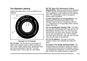
Tire Sidewall Labeling
Useful information about a tire is molded into its
sidewall.
Passenger Car Tire Example
(A) Tire Size:The tire size is a combination of
letters and numbers used to define a particular
tire's width, height, aspect ratio, construction type
and service description. See the “Tire Size”
illustration later in this section for more detail. (B) TPC Spec (Tire Performance Criteria
Specification)
:Original equipment tires designed
to GM's specific tire performance criteria have a
TPC specification code molded onto the sidewall.
GM's TPC specifications meet or exceed all
federal safety guidelines.
(C) DOT (Department of Transportation)
:The
Department of Transportation (DOT) code
indicates that the tire is in compliance with the
U.S. Department of Transportation Motor Vehicle
Safety Standards.
(D) Tire Identification Number (TIN)
:The letters
and numbers following the DOT code are the Tire
Identification Number (TIN). The TIN shows the
manufacturer and plant code, tire size, and date
the tire was manufactured. The TIN is molded
onto both sides of the tire, although only one side
may have the date of manufacture.
(E) Tire Ply Material
:The type of cord and
number of plies in the sidewall and under the
tread.
(F) Uniform Tire Quality Grading (UTQG)
:Tire
manufacturers are required to grade tires based
on three performance factors: treadwear, traction
and temperature resistance. For more information
see Uniform Tire Quality Grading
on page 6‑70.
6-49
Page 360 of 470

Black plate (50,1)Cadillac DTS Owner Manual - 2011
(G) Maximum Cold Inflation Load Limit:
Maximum load that can be carried and the
maximum pressure needed to support that load.
For information on recommended tire pressure
seeInflation - Tire Pressure
on page 6‑57and
Loading the Vehicle
on page 5‑18.
Compact Spare Tire Example
(A) Temporary Use Only:The compact spare
tire or temporary use tire has a tread life of
approximately 3,000 miles (5 000 km) and should not be driven at speeds over 65 mph (105 km/h).
The compact spare tire is for emergency use
when a regular road tire has lost air and gone flat.
See
Spare Tire
on page 6‑93andIf a Tire Goes
Flat
on page 6‑73.
(B) Tire Ply Material
:The type of cord and
number of plies in the sidewall and under the
tread.
(C) Tire Identification Number (TIN)
:The Tire
Identification Number (TIN). The TIN shows the
manufacturer and plant code, tire size, and date
the tire was manufactured. The TIN is molded
onto both sides of the tire, although only one side
may have the date of manufacture.
(D) Maximum Cold Inflation Load Limit
:
Maximum load that can be carried and the
maximum pressure needed to support that load.
See Inflation - Tire Pressure
on page 6‑57and
Loading the Vehicle
on page 5‑18.
6-50