Page 17 of 88

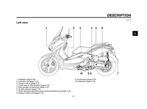
�Keep other immobilizer system
keys away from the main
switch as they may cause sig-
nal interference.EAU10472
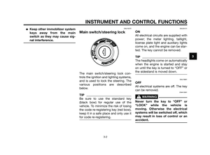
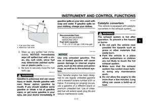
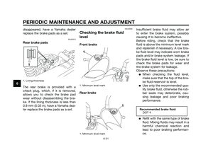
Main switch/steering lock
The main switch/steering lock con-
trols the ignition and lighting systems,
and is used to lock the steering. The
various positions are described
below.
TIP
Be sure to use the standard key
(black bow) for regular use of the
vehicle. To minimize the risk of losing
the code re-registering key (red bow),
keep it in a safe place and only use it
for code re-registering.
EAU34121
ON
All electrical circuits are supplied with
power; the meter lighting, taillight,
license plate light and auxiliary lights
come on, and the engine can be star-
ted. The key cannot be removed.
TIP
The headlights come on automatically
when the engine is started and stay
on until the key is turned to “OFF” or
the sidestand is moved down.
EAU10661
OFF
All electrical systems are off. The key
can be removed.
EWA10061
Never turn the key to “OFF” or
“LOCK” while the vehicle is
moving. Otherwise the electrical
systems will be switched off, which
may result in loss of control or an
accident.
WARNING
INSTRUMENT AND CONTROL FUNCTIONS
3-2
3
39D-F8199-E0 4/11/09 20:21 Página 17
Page 18 of 88
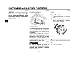
EAU10683
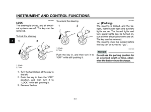
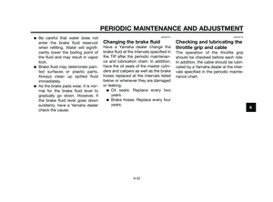
LOCK
The steering is locked, and all electri-
cal systems are off. The key can be
removed.
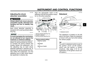
T
o lock the steering
1. Push
2. Turn
1. Turn the handlebars all the way to
the left.
2. Push the key in from the “OFF”
position, and then turn it to
“LOCK” while still pushing it.
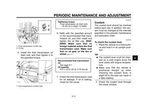
3. Remove the key.T
o unlock the steering
1. Push
2. Turn
Push the key in, and then turn it to
“OFF” while still pushing it.
EAU10941
(Parking)
The steering is locked, and the tai-
llight, license plate light and auxiliary
lights are on. The hazard lights and
turn signal lights can be turned on,
but all other electrical systems are off.
The key can be removed.
The steering must be locked before
the key can be turned to “ ”.
ECA11020
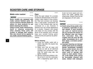
Do not use the parking position for
an extended length of time, other-
wise the battery may discharge.
NOTICE
INSTRUMENT AND CONTROL FUNCTIONS
3-3
3
39D-F8199-E0 4/11/09 20:21 Página 18
Page 19 of 88

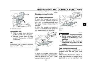
EAU11004
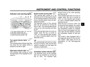
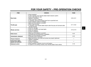
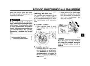
Indicator and warning lights
1. Turn signal indicator lights “ ” and “ ”
2. High beam indicator light “ ”
3. Immobilizer system indicator light
4. Engine trouble warning light “ ”
EAU11030
Turn signal indicator lights “ ”
and “ ”
The corresponding indicator light flas-
hes when the turn signal switch is
pushed to the left or right.
EAU11080
High beam indicator light “ ”
This indicator light comes on when
the high beam of the headlight is swit-
ched on.
EAU43023
Engine trouble warning light “ ”
This warning light comes on if an
electrical circuit monitoring the engine
is not working correctly. If this occurs,
have a Yamaha dealer check the self-
diagnosis system.
The electrical circuit of the warning
light can be checked by turning the
key to “ON”. The warning light should
come on for a few seconds, and then
go off.
If the warning light does not come on
initially when the key is turned to
“ON”, or if the warning light remains
on, have a Yamaha dealer check the
electrical circuit.
TIP
This warning light will come on when
the key is turned to “ON” and the start
switch is pushed, but this does not
indicate a malfunction.
EAU38623
Immobilizer system indicator light
The electrical circuit of the indicator
light can be checked by turning the
key to “ON”. The indicator lightshould come on for a few seconds,
and then go off.
If the indicator light does not come on
initially when the key is turned to
“ON”, or if the indicator light remains
on, have a Yamaha dealer check the
electrical circuit.
When the key is turned to “OFF” and
30 seconds have passed, the indica-
tor light will start flashing indicating
the immobilizer system is enabled.
After 24 hours have passed, the indi-
cator light will stop flashing, however
the immobilizer system is still ena-
bled.
This model is also equipped with a
self-diagnosis device for the immobi-
lizer system. (See page 3-6 for an
explanation of the self-diagnosis
device.)
1234
INSTRUMENT AND CONTROL FUNCTIONS
3-4
3
39D-F8199-E0 4/11/09 20:21 Página 19
Page 20 of 88
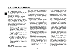
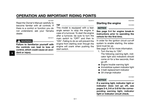
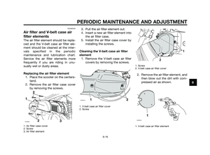
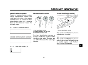
EAUS1860
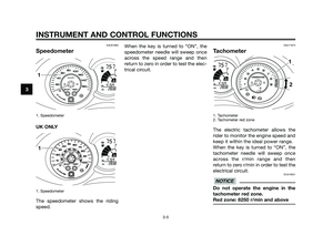
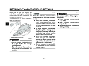
Speedometer
1. Speedometer
UK ONLY
1. Speedometer
The speedometer shows the riding
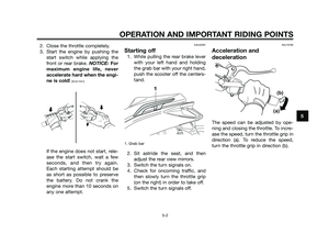
speed.When the key is turned to “ON”, the
speedometer needle will sweep once
across the speed range and then
return to zero in order to test the elec-
trical circuit.
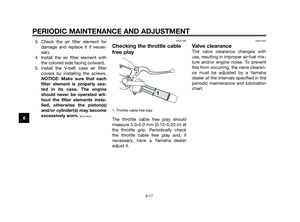
EAU11872
Tachometer
1. Tachometer
2. Tachometer red zone
The electric tachometer allows the
rider to monitor the engine speed and
keep it within the ideal power range.
When the key is turned to “ON”, the
tachometer needle will sweep once
across the r/min range and then
return to zero r/min in order to test the
electrical circuit.
ECA10031
Do not operate the engine in the
tachometer red zone.
Red zone: 8250 r/min and above
NOTICE
1
2
1
1
INSTRUMENT AND CONTROL FUNCTIONS
3-5
3
39D-F8199-E0 4/11/09 20:21 Página 20
Page 21 of 88

EAUS1681
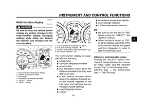
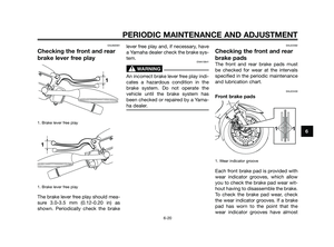
Multi-function displayEWA12312
Be sure to stop the vehicle before
making any setting changes to the
multi-function display. Changing
settings while riding can distract
the operator and increase the risk
of an accident.
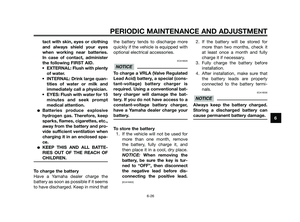
1. Clock/ambient temperature display
2. Coolant temperature meter
3. Fuel meter
4. Odometer/fuel reserve tripmeter
5. “SELECT” button
6. “RESET” button1. V-belt replacement indicator “V-BELT”
2. Fuel level warning indicator “ ”
3. Coolant temperature warning indicator “ ”
4. Oil change indicator “OIL”
The multi-function display is equip-
ped with the following:
�a fuel meter
�a coolant temperature meter
�an odometer
�two tripmeters (which show the
distance traveled since they were
last set to zero)
�a fuel reserve tripmeter (which
shows the distance traveled sin-
ce the bottom segment of the
fuel meter and fuel level warning
indicator started flashing)
�a self-diagnosis device
�a clock
�an ambient temperature display
�an oil change indicator
�a V-belt replacement indicator
TIP
�Be sure to turn the key to “ON”
before using the “SELECT” and
“RESET” buttons.
�When the key is turned to “ON”,
all of the display segments of the
multi-function display will appear
and then disappear, in order to
test the electrical circuit.
Odometer and tripmeter modes
Pushing the “SELECT” button swit-
ches the display between the odome-
ter mode “Odo” and the tripmeter
modes “Trip” in the following order:
Odo/Trip (top) �Trip (bottom)/Trip
(top) �Odo/Trip (top)
123
4
1
2
3
4
5
6
WARNING
INSTRUMENT AND CONTROL FUNCTIONS
3-6
3
39D-F8199-E0 4/11/09 20:21 Página 21
Page 22 of 88
 of fuel remains in
the fuel tank, the bottom segment of
the fuel meter and fuel level warning
indicator will start flashing, and the
display will a")
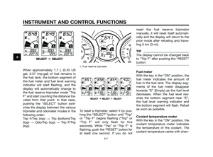
When approximately 1.7 L (0.45 US
gal, 0.37 Imp.gal) of fuel remains in
the fuel tank, the bottom segment of
the fuel meter and fuel level warning
indicator will start flashing, and the
display will automatically change to
the fuel reserve tripmeter mode “Trip
F” and start counting the distance tra-
veled from that point. In that case,
pushing the “SELECT” button swit-
ches the display between the various
tripmeter and odometer modes in the
following order:
Trip F/Trip (top) �Trip (bottom)/Trip
(top) �Odo/Trip (top) �Trip F/Trip
(top)
1. Fuel reserve tripmeter
To reset a tripmeter, select it by pus-
hing the “SELECT” button until “Trip”
or “Trip F” begins flashing (“Trip” or
“Trip F” will only flash for five
seconds). While “Trip” or “Trip F” is
flashing, push the “RESET” button for
at least one second. If you do notreset the fuel reserve tripmeter
manually, it will reset itself automati-
cally and the display will return to the
prior mode after refueling and trave-
ling 5 km (3 mi).
TIP
The display cannot be changed back
to “Trip F” after pushing the “RESET”
button.
Fuel meter
With the key in the “ON” position, the
fuel meter indicates the amount of
fuel in the fuel tank. The display seg-
ments of the fuel meter disappear
towards “E” (Empty) as the fuel level
decreases. When the fuel level rea-
ches the bottom segment near “E”,
the fuel level warning indicator and
the bottom segment will flash. Refuel
as soon as possible.
Coolant temperature meter
With the key in the “ON” position, the
coolant temperature meter indicates
the temperature of the coolant. The
coolant temperature varies with chan-
1
INSTRUMENT AND CONTROL FUNCTIONS
3-7
3
39D-F8199-E0 4/11/09 20:21 Página 22
Page 23 of 88
.
ECA10021
Do not continue to operat")
ges in the weather and engine load. If
the top segment and coolant tempe-
rature warning indicator flash, stop
the vehicle and let the engine cool.
(See page 6-30).
ECA10021
Do not continue to operate the
engine if it is overheating.
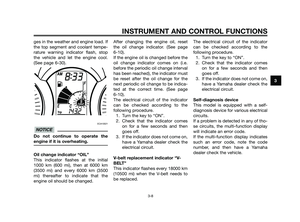
Oil change indicator “OIL”
This indicator flashes at the initial
1000 km (600 mi), then at 6000 km
(3500 mi) and every 6000 km (3500
mi) thereafter to indicate that the
engine oil should be changed.After changing the engine oil, reset
the oil change indicator. (See page
6-10).
If the engine oil is changed before the
oil change indicator comes on (i.e.
before the periodic oil change interval
has been reached), the indicator must
be reset after the oil change for the
next periodic oil change to be indica-
ted at the correct time. (See page
6-10).
The electrical circuit of the indicator
can be checked according to the
following procedure.
1. Turn the key to “ON”.
2. Check that the indicator comes
on for a few seconds and then
goes off.
3. If the indicator does not come on,
have a Yamaha dealer check the
electrical circuit.
V-belt replacement indicator “V-
BELT”
This indicator flashes every 18000 km
(10500 mi) when the V-belt needs to
be replaced.The electrical circuit of the indicator
can be checked according to the
following procedure.
1. Turn the key to “ON”.
2. Check that the indicator comes
on for a few seconds and then
goes off.
3. If the indicator does not come on,
have a Yamaha dealer check the
electrical circuit.
Self-diagnosis device
This model is equipped with a self-
diagnosis device for various electrical
circuits.
If a problem is detected in any of tho-
se circuits, the multi-function display
will indicate an error code.
If the multi-function display indicates
such an error code, note the code
number, and then have a Yamaha
dealer check the vehicle.
NOTICE
INSTRUMENT AND CONTROL FUNCTIONS
3-8
3
39D-F8199-E0 4/11/09 20:21 Página 23
Page 24 of 88

ECA11790
If the multi-function display indica-
tes an error code, the vehicle
should be checked as soon as pos-
sible in order to avoid engine
damage.
The self-diagnosis device also
detects problems in the immobilizer
system circuits.
If a problem is detected in the immo-
bilizer system circuits, the immobilizer
system indicator light will flash and
the multi-function display will indicate
an error code when the key is turned
to “ON”.
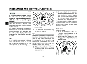
TIP
If the multi-function display indicates
error code 52, this could be caused
by transponder interference. If this
error appears, try the following.
1. Error code display
1. Use the code re-registering key
to start the engine.
TIP
Make sure there are no other immobi-
lizer keys close to the main switch,
and do not keep more than one
immobilizer key on the same key ring!
Immobilizer system keys may cause
signal interference, which may pre-
vent the engine from starting.
2. If the engine starts, turn it off, and
try starting the engine with the
standard keys.3. If one or both of the standard
keys do not start the engine, take
the vehicle, the code re-registe-
ring key and both standard keys
to a Yamaha dealer and have the
standard keys re-registered.
If the multi-function display indicates
any error codes, note the code num-
ber, and then have a Yamaha dealer
check the vehicle.
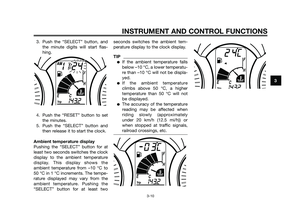
Clock mode
T
o set the clock:
1. Push the “SELECT” button and
“RESET” button together for at
least two seconds.
2. When the hour digits start flas-
hing, push the “RESET” button to
set the hours.
1
NOTICE
INSTRUMENT AND CONTROL FUNCTIONS
3-9
3
39D-F8199-E0 4/11/09 20:21 Página 24