Page 25 of 106

INSTRUMENT AND CONTROL FUNCTIONS
3-11
3 4. Push “RESET”.
Push “SELECT” and highlight “On”
to activate the indicator light; the
indicator light comes on and stays
on when activated.
Push “SELECT” and highlight
“Flash” to activate the indicator
light; the indicator light flashes
when activated.
Push “SELECT” and highlight “Off”
to deactivate the indicator light; the
indicator light neither comes on
nor flashes.
TIPThe indicator light flashes once every
two seconds to show that it has been
deactivated. The indicator light goes off
after this menu is exited.5. Push “RESET” to set the shift tim-
ing indicator light activity.
6. Push “RESET” again to return to
the previous menu.
Setting the r/min in relation to the shifttiming indicator lightThis function allows you to select the
engine speed at which the indicator
light is activated and deactivated. All
gears can be set to the same activa-
tion/deactivation r/min or the gears can
be set individually.
Push “SELECT” to highlight “r/min set-
ting”, then push “RESET”.
TIPThe shift timing indicator light can be
set to activate between 3000 r/min and
10500 r/min and deactivate between
3500 r/min and 11000 r/min in incre-
ments of 500 r/min.To set all gears to the same r/min:
1. Push “SELECT” to highlight “All”.
2. Push “RESET”; “On” is displayed.
3. Push “RESET” and the r/min digits
start flashing.
4. Push “SELECT” to highlight the
engine speed at which the shift
timing indicator light is activated.
U2S3E1E0.book Page 11 Friday, August 7, 2009 1:06 PM
Page 26 of 106

INSTRUMENT AND CONTROL FUNCTIONS
3-12
35. Push “RESET” to set the selected
engine speed. “Off” is highlighted
and the r/min digits start flashing.
6. Push “SELECT” to highlight the
engine speed at which the shift
timing indicator light is deactivat-
ed.
7. Push “RESET” to set the selected
engine speed.
8. Push “RESET” again to return to
the previous menu.
To set individual gear r/min:
1. Push “SELECT” to highlight gears
from “1st” through “5th”, then push
“RESET”.
2. Push “RESET” and the r/min digits
for the highlighted gear start flash-
ing, then perform steps 4–8 under
“To set all gears to the same
r/min:” in order to set the r/min for
the individual gears.
TIPAfter setting r/min for individual gears, if
“All” is chosen, all previously set r/min
for individual gears return to the default
settings of 9000 (activation) and 11000
(deactivation).3. Push “SELECT” to scroll to“”,
then push “RESET” to return to the
previous menu.
Setting the shift timing indicator lightbrightnessThis function allows you to adjust the
brightness of the shift timing indicator
light.
1. Push “SELECT” to highlight
“Brightness”.
2. Push “RESET” and the brightness
level segments start flashing.3. Push “SELECT” to highlight the
desired brightness level.
4. Push “RESET” to set the selected
brightness level.
5. Push “RESET” to return to the pre-
vious menu.
6. Push “SELECT” to scroll to“”,
then push “RESET”. This allows
you to select another item in the
menu.
Setting the clock
1. Push “SELECT” to highlight “Dis-
play”.
2. Push “RESET”; the following
screen is displayed.
3. Push “RESET” and the hour digits
start flashing.
4. Push “SELECT” to increment the
hours.
U2S3E1E0.book Page 12 Friday, August 7, 2009 1:06 PM
Page 27 of 106

INSTRUMENT AND CONTROL FUNCTIONS
3-13
3 5. Push “RESET”, and the minute
digits start flashing.
6. Push “SELECT” to increment the
minutes.
7. Push “RESET” to start the clock.
8. Push “RESET” again to return to
the previous menu.
Resetting all the brightness and shift
timing indicator light functions:This resets ALL settings made to the
brightness and shift timing indicator
light functions.
1. Push “SELECT” to highlight “Dis-
play”.
2. Push “RESET”.
3. Push “SELECT” to highlight “All re-
set”.
4. Push “RESET”, then push “SE-
LECT” to highlight “Yes”.5. Push “RESET” to reset the bright-
ness and shift timing light indicator
values to the factory setting. The
display returns to the Normal
mode.
TIPTo perform further multi-function dis-
play settings, enter the Select mode
again by pushing and holding “SE-
LECT” and “RESET” for at least three
seconds.Using the stopwatchThe stopwatch can be activated as fol-
lows.
1. Push “SELECT” to highlight “Stop-
watch”.
2. Push “RESET”.3. Push “SELECT” to highlight “Stop-
watch”.
4. Push “RESET”.
The multi-function display chang-
es to the Normal mode and the
stopwatch is displayed in place of
the clock.
5. Push “SELECT” to start the stop-
watch.
6. Push the start switch“” or “SE-
LECT” to stop the stopwatch.
7. Push “RESET” to reset the stop-
watch.
TIP�
If neither “SELECT” nor “RESET”
are pushed for one minute, the
screen automatically changes to
the Normal mode.
U2S3E1E0.book Page 13 Friday, August 7, 2009 1:06 PM
Page 28 of 106

INSTRUMENT AND CONTROL FUNCTIONS
3-14
3
�
Pushing “RESET” for at least two
seconds changes the screen to
the Normal mode.
�
To perform further multi-function
display settings, enter the Select
mode again by pushing and hold-
ing “SELECT” and “RESET” for at
least three seconds.
Using the countdown clock:The countdown clock can be activated
as follows.
1. Push “SELECT” to highlight “Stop-
watch”.
2. Push “RESET”.
3. Push “SELECT” to highlight
“Countdown”.
4. Push “RESET”. The multi-function
display changes to the Normal
mode, the stopwatch is displayed
in place of the clock, and the trans-
mission gear indicator changes to
the countdown clock.5. Push “SELECT” or shift into gear
and the countdown clock starts
counting down from “5”. Simulta-
neously, the shift timing indicator
light flashes according to the num-
ber displayed (i.e., when “5” is dis-
played, the indicator light flashes
five times, when “4” is displayed,
the indicator light flashes four
times, etc.). The stopwatch starts
counting when the countdown
clock finishes counting.
6. Push the start switch“” or “SE-
LECT” to stop the countdown
clock.
7. Push “RESET” to reset the count-
down clock and stopwatch.
8. Push “RESET” to reset the count-
down clock, and then repeat steps
5–6, OR push “RESET” again for
at least two seconds to enter the
Normal mode.
TIPTo perform further multi-function dis-
play settings, be sure the transmis-
sion is in neutral, then enter the
Select mode again by pushing and
holding “SELECT” and “RESET” for at
least three seconds.Checking and resetting the system sta-tusThe status/readings of the following
items are displayed, and the tripmeters
can be reset.�
tripmeters and odometer
�
fuel consumption
�
air intake temperature
�
throttle opening position
TIP�
The “System status” menu cannot
be entered if the fuel level warning
light or coolant temperature warn-
ing light is on.
�
If, when the engine is running
while the system status menu is
displayed, the fuel level warning
U2S3E1E0.book Page 14 Friday, August 7, 2009 1:06 PM
Page 29 of 106

INSTRUMENT AND CONTROL FUNCTIONS
3-15
3 light or coolant temperature warn-
ing light comes on, the Normal
mode is automatically displayed.
1. Push “SELECT” to highlight “Sys-
tem status”, then push “RESET”.
2. Push “SELECT” to highlight “Yes”,
then push “RESET”. (Highlighting
“No” and pushing “RESET” returns
to the previous menu.)
The display changes to the status
screen.Push “SELECT” and the various trip-
meters and the odometer are displayed
in the following order:
(TRIP-F) ‚Üí TRIP-1 ‚Üí TRIP-2 ‚Üí ODO
‚Üí (TRIP-F)
Push “RESET” to reset a tripmeter.
TIP�
For the U.K. only: Push “SELECT”
for at least two seconds to switch
between kilometers and miles.
�
Pushing “RESET” displays the
Normal mode for five seconds.
Pushing “SELECT” and “RESET”
for at least three seconds, chang-
es the display to the Normal mode.
�
To perform further multi-function
display settings, enter the Select
mode again by pushing and hold-
ing “SELECT” and “RESET” for at
least three seconds.
Resetting the maintenance countersThis function allows you to reset the
maintenance counters for the tires, the
engine oil, and an item of your choice.
1. Push “SELECT” to highlight “Main-
tenance”.
2. Push “RESET”.
3. Push “SELECT” to highlight the
item to reset.
1. Odometer/tripmeter/fuel reserve tripmeter
2. Clock
3. Instantaneous fuel consumption
4. Throttle opening position display
5. Transmission gear indicator
6. Air intake temperature display
12 3
654
U2S3E1E0.book Page 15 Friday, August 7, 2009 1:06 PM
Page 30 of 106

INSTRUMENT AND CONTROL FUNCTIONS
3-16
34. Push “RESET” to reset the item.
TIP�
The bottom area was left blank for
another item the rider cares to
check the distance of since it has
been changed, replaced or
checked (i.e., air filter element, en-
gine parts, etc.).
�
Letters and numbers cannot be
entered in the blank area.
5. Push “SELECT” to scroll to“”.
6. Push “RESET” to return to the pre-
vious menu.
Self-diagnosis device
TIPThe display indicates error codes only
in the Normal mode.This model is equipped with a self-diag-
nosis device for various electrical cir-
cuits.
If a problem is detected in any of those
circuits, the engine trouble warning light
comes on and the display indicates an
error code.NOTICE
ECA11590
If the display indicates an error
code, the vehicle should be checked
as soon as possible in order to avoid
engine damage.The self-diagnosis device also detects
problems in the immobilizer system cir-
cuits.
If a problem is detected in any of the im-
mobilizer system circuits, the immobi-
lizer system indicator light flashes and
the display indicates an error code.
TIPIf the display indicates error code 52,
this could be caused by transponder in-
terference. If this error code appears,
try the following.1. Use the code re-registering key to
start the engine.TIPMake sure there are no other immobi-
lizer keys close to the main switch, and
do not keep more than one immobilizer
key on the same key ring! Immobilizer
system keys may cause signal interfer-
ence, which may prevent the engine
from starting.2. If the engine starts, turn it off and
try starting the engine with the
standard keys.
3. If one or both of the standard keys
do not start the engine, take the
vehicle, the code re-registering
key and both standard keys to a
Yamaha dealer and have the stan-
dard keys re-registered.
If the display indicates any error codes,
note the code number, and then have a
Yamaha dealer check the vehicle.
1. Error code display
1
U2S3E1E0.book Page 16 Friday, August 7, 2009 1:06 PM
Page 31 of 106
INSTRUMENT AND CONTROL FUNCTIONS
3-17
3
EAU12331
Anti-theft alarm (optional) This model can be equipped with an
optional anti-theft alarm by a Yamaha
dealer. Contact a Yamaha dealer for
more information.
EAU12348
Handlebar switches LeftRight
EAU12350
Pass switch“”
Press this switch to flash the headlight.
EAU12400
Dimmer switch“/”
Set this switch to“” for the high
beam and to“” for the low beam.
EAU12460
Turn signal switch“/”
To signal a right-hand turn, push this
switch to“”. To signal a left-hand
turn, push this switch to“”. When re-
leased, the switch returns to the center
1. Pass switch“”
2. Dimmer switch“/”
3. Hazard switch“”
4. Horn switch“”
5. Turn signal switch“/”
5
43
2
1
1. Engine stop switch“/”
2. Start switch“”
1
2
U2S3E1E0.book Page 17 Friday, August 7, 2009 1:06 PM
Page 32 of 106

INSTRUMENT AND CONTROL FUNCTIONS
3-18
3position. To cancel the turn signal
lights, push the switch in after it has re-
turned to the center position.
EAU12500
Horn switch“”
Press this switch to sound the horn.
EAU12660
Engine stop switch“/”
Set this switch to“” before starting
the engine. Set this switch to“” to
stop the engine in case of an emergen-
cy, such as when the vehicle overturns
or when the throttle cable is stuck.
EAU12711
Start switch“”
Push this switch to crank the engine
with the starter. See page 5-1 for start-
ing instructions prior to starting the en-
gine.
EAU42340
The engine trouble warning light and
ABS warning light will come on when
the key is turned to “ON” and the start
switch is pushed, but this does not indi-
cate a malfunction.
EAU12733
Hazard switch“”
With the key in the “ON” or“” posi-
tion, use this switch to turn on the haz-
ard lights (simultaneous flashing of all
turn signal lights).
The hazard lights are used in case of
an emergency or to warn other drivers
when your vehicle is stopped where it
might be a traffic hazard.NOTICE
ECA10061
Do not use the hazard lights for an
extended length of time with the en-
gine not running, otherwise the bat-
tery may discharge.
EAU12830
Clutch lever The clutch lever is located at the left
handlebar grip. To disengage the
clutch, pull the lever toward the handle-
bar grip. To engage the clutch, release
the lever. The lever should be pulled
rapidly and released slowly for smooth
clutch operation.
The clutch lever is equipped with a
clutch lever position adjusting dial. To
adjust the distance between the clutch
lever and the handlebar grip, turn the
adjusting dial while holding the lever
pushed away from the handlebar grip.1. Clutch lever
2. Clutch lever position adjusting dial
3. Arrow mark
4. Distance between clutch lever and handlebar
grip
4
1
2
3
U2S3E1E0.book Page 18 Friday, August 7, 2009 1:06 PM
 1
1 2
2 3
3 4
4 5
5 6
6 7
7 8
8 9
9 10
10 11
11 12
12 13
13 14
14 15
15 16
16 17
17 18
18 19
19 20
20 21
21 22
22 23
23 24
24 25
25 26
26 27
27 28
28 29
29 30
30 31
31 32
32 33
33 34
34 35
35 36
36 37
37 38
38 39
39 40
40 41
41 42
42 43
43 44
44 45
45 46
46 47
47 48
48 49
49 50
50 51
51 52
52 53
53 54
54 55
55 56
56 57
57 58
58 59
59 60
60 61
61 62
62 63
63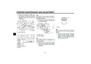 64
64 65
65 66
66 67
67 68
68 69
69 70
70 71
71 72
72 73
73 74
74 75
75 76
76 77
77 78
78 79
79 80
80 81
81 82
82 83
83 84
84 85
85 86
86 87
87 88
88 89
89 90
90 91
91 92
92 93
93 94
94 95
95 96
96 97
97 98
98 99
99 100
100 101
101 102
102 103
103 104
104 105
105 This model can be equipped with an
optional anti-theft alarm by a Yamaha
dealer. Contact a Yamaha dealer for
more informati")