Page 65 of 106

PERIODIC MAINTENANCE AND ADJUSTMENT
6-12
6 8. Install the engine oil drain bolt and
its new gasket, and then tighten
the bolt to the specified torque.
9. Refill with the specified amount of
the recommended engine oil, and
then install and tighten the oil filler
cap.
TIPBe sure to wipe off spilled oil on any
parts after the engine and exhaust sys-
tem have cooled down.NOTICE
ECA11620
�
In order to prevent clutch slip-
page (since the engine oil also
lubricates the clutch), do not
mix any chemical additives. Do
not use oils with a diesel speci-
fication of “CD” or oils of a high-
er quality than specified. In
addition, do not use oils labeled
“ENERGY CONSERVING II” or
higher.
�
Make sure that no foreign mate-
rial enters the crankcase.
10. Start the engine, and then let it idle
for several minutes while checking
it for oil leakage. If oil is leaking, im-
mediately turn the engine off and
check for the cause.TIPAfter the engine is started, the engine
oil level warning light should go off if the
oil level is sufficient.NOTICE
ECA10401
If the oil level warning light flickers
or remains on even if the oil level is
correct, immediately turn the engine
off and have a Yamaha dealer check
the vehicle.11. Turn the engine off, wait a few min-
utes until the oil settles, and then
check the oil level and correct it if
necessary.
1. Torque wrenchTightening torque:
Oil filter cartridge:
17 Nm (1.7 m·kgf, 12 ft·lbf)
Tightening torque:
Engine oil drain bolt:
43 Nm (4.3 m·kgf, 31 ft·lbf)
1
Recommended engine oil:
See page 8-1.
Oil quantity:
Without oil filter cartridge replace-
ment:
4.30 L (4.55 US qt, 3.78 Imp.qt)
With oil filter cartridge replacement:
4.70 L (4.97 US qt, 4.14 Imp.qt)
U2S3E1E0.book Page 12 Friday, August 7, 2009 1:06 PM
Page 66 of 106

PERIODIC MAINTENANCE AND ADJUSTMENT
6-13
6
EAU46575
Final gear oil The final gear case must be checked
for oil leakage before each ride. If any
leakage is found, have a Yamaha deal-
er check and repair the vehicle. In addi-
tion, the final gear oil must be checked
and changed as follows at the intervals
specified in the periodic maintenance
and lubrication chart.
WARNING
EWA10370
�
Make sure that no foreign mate-
rial enters the final gear case.
�
Make sure that no oil gets on the
tire or wheel.
To check the final gear oil level
1. Place the vehicle on a level sur-
face and hold it in an upright posi-
tion.TIPMake sure that the vehicle is positioned
straight up when checking the oil level.2. Loosen the final gear oil check bolt
until oil flows out.3. If no oil flows out, remove the final
gear case breather cap by remov-
ing the bolt and washer and then
remove the final gear oil filler bolt
and its gasket.4. Pour the recommended type of oil
in the final gear oil filler hole until it
flows out of the oil check bolt hole.
5. Tighten the oil check bolt to the
specified torque.
6. Check the oil filler bolt gasket for
damage, and replace it if neces-
sary.
1. Final gear oil check bolt
1
1. Final gear case breather cap bolt
2. Washer
3. Final gear case breather cap
4. Final gear oil filler bolt
5. GasketTightening torque:
Final gear oil check bolt:
10 Nm (1.0 m·kgf, 7.2 ft·lbf)3 2 145
U2S3E1E0.book Page 13 Friday, August 7, 2009 1:06 PM
Page 67 of 106

PERIODIC MAINTENANCE AND ADJUSTMENT
6-14
6 7. Install the oil filler bolt and its gas-
ket, and then tighten the bolt to the
specified torque.
8. Install the final gear case breather
cap by installing the washer and
bolt, and then tighten the bolt to the
specified torque.
To change the final gear oil
1. Place the vehicle on a level sur-
face.
2. Place an oil pan under the final
gear case to collect the used oil.
3. Remove the final gear case
breather cap by removing the bolt
and washer.4. Remove the final gear oil filler bolt,
the final gear oil drain bolt and their
gasket to drain the oil from the final
gear case.5. Install the drain bolt and its new
gasket, and then tighten the bolt to
the specified torque.
6. Refill with the recommended final
gear oil.
Tightening torque:
Final gear oil filler bolt:
23 Nm (2.3 m·kgf, 17 ft·lbf)
Tightening torque:
Final gear case breather cap bolt:
10 Nm (1.0 m·kgf, 7.2 ft·lbf)
1. Final gear case breather cap bolt
2. Washer
3. Final gear case breather cap
4. Final gear oil filler bolt
5. Gasket
3 2 145
1. Final gear oil drain bolt
2. Gasket
Tightening torque:
Final gear oil drain bolt:
23 Nm (2.3 m·kgf, 17 ft·lbf)
Recommended final gear oil:
Shaft drive gear oil (Part No.:
9079E-SH001-00)
Oil quantity:
0.30 L (0.32 US qt, 0.26 Imp.qt)
1
12
U2S3E1E0.book Page 14 Friday, August 7, 2009 1:06 PM
Page 68 of 106

PERIODIC MAINTENANCE AND ADJUSTMENT
6-15
67. Check the oil filler bolt gasket for
damage, and replace it if neces-
sary.
8. Install the oil filler bolt and its gas-
ket, and then tighten the bolt to the
specified torque.
9. Install the final gear case breather
cap by installing the washer and
bolt, and then tighten the bolt to the
specified torque.
10. Check the final gear case for oil
leakage. If oil is leaking, check for
the cause.
EAU20070
Coolant The coolant level should be checked
before each ride. In addition, the cool-
ant must be changed at the intervals
specified in the periodic maintenance
and lubrication chart.
EAU46690
To check the coolant level
1. Place the vehicle on a level sur-
face and hold it in an upright posi-
tion.TIP�
The coolant level must be checked
on a cold engine since the level
varies with engine temperature.
�
Make sure that the vehicle is posi-
tioned straight up when checking
the coolant level. A slight tilt to the
side can result in a false reading.
2. Check the coolant level in the cool-
ant reservoir.TIPThe coolant should be between the
minimum and maximum level marks.
3. If the coolant is at or below the
minimum level mark, remove the
coolant reservoir cap guard by re-
moving the bolt, and then remove
the reservoir cap.
4. Add coolant to the maximum level
mark, and then install the reservoir
cap. WARNING! Remove only
the coolant reservoir cap. Never
attempt to remove the radiator
cap when the engine is hot.
[EWA15161]
NOTICE: If coolant is not
available, use distilled water or
soft tap water instead. Do not
Tightening torque:
Final gear oil filler bolt:
23 Nm (2.3 m·kgf, 17 ft·lbf)
Tightening torque:
Final gear case breather cap bolt:
10 Nm (1.0 m·kgf, 7.2 ft·lbf)
1. Coolant reservoir cap
2. Coolant reservoir cap guard
3. Bolt
4. Maximum level mark
5. Minimum level mark
2
1
5 4
3
U2S3E1E0.book Page 15 Friday, August 7, 2009 1:06 PM
Page 69 of 106

PERIODIC MAINTENANCE AND ADJUSTMENT
6-16
6 use hard water or salt water
since it is harmful to the engine.
If water has been used instead
of coolant, replace it with cool-
ant as soon as possible, other-
wise the cooling system will not
be protected against frost and
corrosion. If water has been
added to the coolant, have a
Yamaha dealer check the anti-
freeze content of the coolant as
soon as possible, otherwise the
effectiveness of the coolant will
be reduced.
[ECA10472]
5. Install the coolant reservoir cap
guard by installing the bolt.
EAU46423
To change the coolant
1. Place the vehicle on a level sur-
face and let the engine cool if nec-
essary.
2. Remove cowling A. (See page
6-7.)3. Remove the air intake duct by re-
moving the bolts.
4. Place a container under the engine
to collect the used coolant.
5. Remove the radiator cap.
WARNING! Never attempt to re-
move the radiator cap when the
engine is hot.
[EWA10381]
6. Remove the coolant reservoir cov-
er and coolant reservoir by remov-
ing the bolts.
Coolant reservoir capacity (up to
the maximum level mark):
0.27 L (0.29 US qt, 0.24 Imp.qt)
1. Bolt
2. Air intake duct
11
2
1. Radiator cap
1. Bolt
2. Coolant reservoir cap
3. Coolant reservoir cap guard
4. Coolant reservoir cover
5. Coolant reservoir
1
4
5
1
2
3
1
U2S3E1E0.book Page 16 Friday, August 7, 2009 1:06 PM
Page 70 of 106

PERIODIC MAINTENANCE AND ADJUSTMENT
6-17
67. Remove the coolant reservoir cap
guard by removing the bolt, and
then remove the reservoir cap.
8. Drain the coolant from the coolant
reservoir by turning it upside down.
9. Install the coolant reservoir cover
and the coolant reservoir by plac-
ing them in their original position,
and then installing the bolts.
10. Remove the coolant drain screw
and its O-ring to drain the cooling
system.
11. After the coolant is completely
drained, thoroughly flush the cool-
ing system with clean tap water.
12. Install the coolant drain screw and
its new O-ring.13. Hold the vehicle upright, and pour
the specified amount of the recom-
mended coolant into the radiator
and reservoir. NOTICE: Failing to
hold the vehicle upright when
filling the radiator with coolant
may cause air to be trapped in
the cooling system.
[ECA16540]
14. Install the coolant reservoir cap,
and then install the reservoir cap
guard by installing the bolt.
15. Install the radiator cap.
16. Start the engine, let it idle for sev-
eral minutes, and then turn it off.17. Remove the radiator cap to check
the coolant level in the radiator. If
necessary, add sufficient coolant
until it reaches the top of the radia-
tor, and then install the radiator
cap.
18. Check the coolant level in the res-
ervoir. If necessary, remove the
coolant reservoir cap guard and
the cap, add coolant to the maxi-
mum level mark, and then install
the cap and the cap guard.
19. Start the engine, and then check
the vehicle for coolant leakage. If
coolant is leaking, have a Yamaha
dealer check the cooling system.
20. Install the air intake duct by install-
ing the bolts.
21. Install the cowling.
1. Coolant drain screw
2. O-ring
1
2
Antifreeze/water mixture ratio:
1:1
Recommended antifreeze:
High-quality ethylene glycol anti-
freeze containing corrosion inhibi-
tors for aluminum engines
Coolant quantity:
Radiator capacity (including all
routes):
3.75 L (3.96 US qt, 3.30 Imp.qt)
Coolant reservoir capacity (up to the
maximum level mark):
0.27 L (0.29 US qt, 0.24 Imp.qt)
U2S3E1E0.book Page 17 Friday, August 7, 2009 1:06 PM
Page 71 of 106
PERIODIC MAINTENANCE AND ADJUSTMENT
6-18
6
EAU36764
Air filter element The air filter element must be replaced
at the intervals specified in the periodic
maintenance and lubrication chart.
Have a Yamaha dealer replace the air
filter element.
EAU44734
Checking the engine idling
speed Check the engine idling speed and, if
necessary, have it corrected by a
Yamaha dealer.
EAU21382
Checking the throttle cable
free play The throttle cable free play should mea-
sure 3.0–5.0 mm (0.12–0.20 in) at the
throttle grip. Periodically check the
throttle cable free play and, if neces-
sary, have a Yamaha dealer adjust it.
Engine idling speed:
950–1050 r/min
1. Throttle cable free play
1
U2S3E1E0.book Page 18 Friday, August 7, 2009 1:06 PM
Page 72 of 106

PERIODIC MAINTENANCE AND ADJUSTMENT
6-19
6
EAU21401
Valve clearance The valve clearance changes with use,
resulting in improper air-fuel mixture
and/or engine noise. To prevent this
from occurring, the valve clearance
must be adjusted by a Yamaha dealer
at the intervals specified in the periodic
maintenance and lubrication chart.
EAU21772
Tires To maximize the performance, durabil-
ity, and safe operation of your motorcy-
cle, note the following points regarding
the specified tires.
Tire air pressure
The tire air pressure should be checked
and, if necessary, adjusted before each
ride.
WARNING
EWA10501
Operation of this vehicle with im-
proper tire pressure may cause se-
vere injury or death from loss of
control.�
The tire air pressure must be
checked and adjusted on cold
tires (i.e., when the temperature
of the tires equals the ambient
temperature).
�
The tire air pressure must be ad-
justed in accordance with the
riding speed and with the total
weight of rider, passenger, car-
go, and accessories approved
for this model.
WARNING
EWA10511
Never overload your vehicle. Opera-
tion of an overloaded vehicle could
cause an accident.Tire air pressure (measured on cold
tires):
0–90 kg (0–198 lb):
Front:
250 kPa (2.50 kgf/cm², 36 psi)
Rear:
290 kPa (2.90 kgf/cm², 42 psi)
90–190 kg (198–419 lb):
Front:
250 kPa (2.50 kgf/cm², 36 psi)
Rear:
290 kPa (2.90 kgf/cm², 42 psi)
High-speed riding:
Front:
290 kPa (2.90 kgf/cm², 42 psi)
Rear:
290 kPa (2.90 kgf/cm², 42 psi)
Maximum load*:
190 kg (419 lb)
* Total weight of rider, passenger, car-
go and accessories
U2S3E1E0.book Page 19 Friday, August 7, 2009 1:06 PM
 1
1 2
2 3
3 4
4 5
5 6
6 7
7 8
8 9
9 10
10 11
11 12
12 13
13 14
14 15
15 16
16 17
17 18
18 19
19 20
20 21
21 22
22 23
23 24
24 25
25 26
26 27
27 28
28 29
29 30
30 31
31 32
32 33
33 34
34 35
35 36
36 37
37 38
38 39
39 40
40 41
41 42
42 43
43 44
44 45
45 46
46 47
47 48
48 49
49 50
50 51
51 52
52 53
53 54
54 55
55 56
56 57
57 58
58 59
59 60
60 61
61 62
62 63
63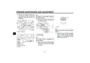 64
64 65
65 66
66 67
67 68
68 69
69 70
70 71
71 72
72 73
73 74
74 75
75 76
76 77
77 78
78 79
79 80
80 81
81 82
82 83
83 84
84 85
85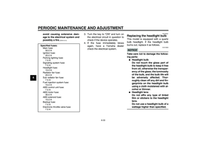 86
86 87
87 88
88 89
89 90
90 91
91 92
92 93
93 94
94 95
95 96
96 97
97 98
98 99
99 100
100 101
101 102
102 103
103 104
104 105
105