Page 57 of 96
PERIODIC MAINTENANCE AND ADJUSTMENT
6-11
2
3
4
5
67
8
9
TIP
Skip steps 5–7 if the oil filter element is
not being replaced.
5. Remove the oil filter element cover
by removing the bolts.6. Remove and replace the oil filter
element and O-rings.7. Install the oil filter element cover by
installing the bolts, and then tight-
en the bolts to the specified torque.
TIP
Make sure that the O-rings are properly
seated.
8. Install the engine oil drain bolts
and their new gasket, and then
tighten the bolts to the specified
torques.
1. Engine oil drain bolt B
2. Gasket
2
1
1. Oil filter element cover
2. Bolt
1
1
2
1. Oil filter element
2. O-ring
Tightening torque:
Oil filter element cover bolt:
10 Nm (1.0 m·kgf, 7.2 ft·lbf)
1
2
✼✥✯✣✲� ✤✤ �
���
�
����������������
Page 58 of 96

PERIODIC MAINTENANCE AND ADJUSTMENT
6-12
1
2
3
4
5
6
7
8
9
9. Refill with the specified amount of
the recommended engine oil, and
then install and tighten the oil filler
cap.
TIP
Be sure to wipe off spilled oil on any
parts after the engine and exhaust sys-
tem have cooled down.
NOTICE
ECA11620
�
In order to prevent clutch slip-
page (since the engine oil also
lubricates the clutch), do not
mix any chemical additives. Donot use oils with a diesel speci-
fication of “CD” or oils of a high-
er quality than specified. In
addition, do not use oils labeled
“ENERGY CONSERVING II” or
higher.
�
Make sure that no foreign mate-
rial enters the crankcase.
10. Start the engine, and then let it idle
for several minutes while checking
it for oil leakage. If oil is leaking, im-
mediately turn the engine off and
check for the cause.
11. Turn the engine off, and then
check the oil level and correct it if
necessary.
EAU20070
Coolant
The coolant level should be checked
before each ride. In addition, the cool-
ant must be changed at the intervals
specified in the periodic maintenance
and lubrication chart.
EAU38583
To check the coolant level
1. Place the vehicle on a level sur-
face and hold it in an upright posi-
tion.
TIP
�
The coolant level must be checked
on a cold engine since the level
varies with engine temperature.
�
Make sure that the vehicle is posi-
tioned straight up when checking
the coolant level. A slight tilt to the
side can result in a false reading.
2. Check the coolant level in the cool-
ant reservoir.
TIP
The coolant should be between the
minimum and maximum level marks.
Tightening torques:
Engine oil drain bolt A:
35 Nm (3.5 m·kgf, 25 ft·lbf)
Engine oil drain bolt B:
30 Nm (3.0 m·kgf, 21.7 ft·lbf)
Recommended engine oil:
See page 8-1.
Oil quantity:
Without oil filter element replace-
ment:
3.80 L (4.02 US qt, 3.34 Imp.qt)
With oil filter element replacement:
3.90 L (4.12 US qt, 3.43 Imp.qt)
✼✥✯✣✲� ✤✥ �
���
�
����������������
Page 59 of 96

PERIODIC MAINTENANCE AND ADJUSTMENT
6-13
2
3
4
5
67
8
9 For TDM900
For TDM900A
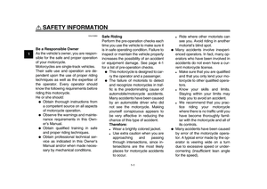
3. If the coolant is at or below the
minimum level mark, remove pan-
el B for TDM900 or panel A for
TDM900A (See page 6-7.), re-
move the reservoir cap, add cool-
ant to the maximum level mark,
and then install the reservoir cap
and the panel.
WARNING! Re-
move only the coolant reservoir
cap. Never attempt to remove
the radiator cap when the en-
gine is hot.
[EWA15161]
NOTICE:
If
coolant is not available, use dis-
tilled water or soft tap water in-
stead. Do not use hard water or
salt water since it is harmful to
the engine. If water has been
used instead of coolant, replace
it with coolant as soon as possi-
ble, otherwise the cooling sys-
tem will not be protected against
frost and corrosion. If water has
been added to the coolant, have
a Yamaha dealer check the anti-
freeze content of the coolant as
soon as possible, otherwise the
effectiveness of the coolant will
be reduced.
[ECA10472]
For TDM900
For TDM900A
1. Coolant reservoir
2. Maximum level mark
3. Minimum level mark
1. Maximum level mark
2. Coolant reservoir
3. Minimum level mark
1 2
33 1
2
1. Coolant reservoir cap
1. Coolant reservoir cap
Coolant reservoir capacity (up to the
maximum level mark):
0.25 L (0.26 US qt, 0.22 Imp.qt)
1
1
✼✥✯✣✲� ✤✦ �
���
�
����������������
Page 60 of 96

PERIODIC MAINTENANCE AND ADJUSTMENT
6-14
1
2
3
4
5
6
7
8
9
EAU27055
Replacing the air filter element
The air filter element should be re-
placed at the intervals specified in the
periodic maintenance and lubrication
chart. Replace the air filter element
more frequently if you are riding in un-
usually wet or dusty areas.
1. Remove the seat. (See
page 3-16.)
2. Remove cowlings A and B as well
as panels A and B. (See
page 6-7.)
3. Remove the fuel tank bolts.
TIP
For TDM900, skip steps 4 and 12.
4. Remove the rear brake fluid reser-
voir holder by removing the bolt.
For TDM900A
5. Lift the fuel tank away from the air
filter case, but do not disconnect
the fuel hoses.
WARNING! Make
sure that the fuel tank is well
supported. Do not tilt or pull the
fuel tank too much, otherwise
the fuel hoses may come loose,
which could cause fuel leakage
and a fire hazard.
[EWA10411]
6. Remove the air filter case cover by
removing the screws.
1. Bolt
1
1. Bolt1
1. Rear brake fluid reservoir
2. Rear brake fluid reservoir holder
3. Bolt
12
3
✼✥✯✣✲� ✤✧ �
���
�
����������������
Page 61 of 96

PERIODIC MAINTENANCE AND ADJUSTMENT
6-15
2
3
4
5
67
8
9
7. Pull the air filter element out.
8. Insert a new air filter element into
the air filter case.
NOTICE:
Make
sure that the air filter element is
properly seated in the air filtercase. The engine should never
be operated without the air filter
element installed, otherwise the
piston(s) and/or cylinder(s) may
become excessively worn.
[ECA10481]
9. Install the air filter case cover by in-
stalling the screws.
10. Place the fuel tank in its original
position. Make sure that the fuel
hoses are properly connected and
routed, and are not pinched. Be
sure to place the fuel tank breather
hose and the overflow hose in their
original position.
WARNING! Be-
fore installing the fuel tank,
make sure that the fuel hoses
are not damaged. If any fuel
hose is damaged, do not start
the engine but have a Yamaha
dealer replace the hose, other-
wise fuel may leak, creating a
fire hazard.
[EWA11331]
11. Install the fuel tank bolts.
12. Install the rear brake fluid reservoir
holder by installing the bolt.
13. Install the panels and cowlings.
14. Install the seat.
1. Air filter case cover
2. Screw
1. Air filter element
1 2
2 21
1. Fuel tank breather/overflow hose
2. Fuel hose
1. Original position (paint mark)
12
1
✼✥✯✣✲� ✤� �
���
�
����������������
Page 62 of 96

PERIODIC MAINTENANCE AND ADJUSTMENT
6-16
1
2
3
4
5
6
7
8
9
EAU34301
Adjusting the engine idling
speed
The engine idling speed must be
checked and, if necessary, adjusted as
follows at the intervals specified in the
periodic maintenance and lubrication
chart.
The engine should be warm before
making this adjustment.
Check the engine idling speed and, if
necessary, adjust it to specification by
turning the idle adjusting screw. To in-
crease the engine idling speed, turn the
screw in direction (a). To decrease the
engine idling speed, turn the screw in
direction (b).
TIP
If the specified idling speed cannot be
obtained as described above, have a
Yamaha dealer make the adjustment.
EAU21383
Checking the throttle cable
free play
The throttle cable free play should mea-
sure 3.0–5.0 mm (0.12–0.20 in) at the
inner edge of the throttle grip. Periodi-
cally check the throttle cable free play
and, if necessary, have a Yamaha
dealer adjust it.
1. Idle adjusting screw
Engine idling speed:
1100–1200 r/min
1(a)
(b)
1. Throttle cable free play
1
✼✥✯✣✲� ✤✩ �
���
�
����������������
Page 63 of 96

PERIODIC MAINTENANCE AND ADJUSTMENT
6-17
2
3
4
5
67
8
9
EAU21401
Valve clearance
The valve clearance changes with use,
resulting in improper air-fuel mixture
and/or engine noise. To prevent this
from occurring, the valve clearance
must be adjusted by a Yamaha dealer
at the intervals specified in the periodic
maintenance and lubrication chart.
EAU33042
Tires
To maximize the performance, durabil-
ity, and safe operation of your motorcy-
cle, note the following points regarding
the specified tires.
Tire air pressure
The tire air pressure should be checked
and, if necessary, adjusted before each
ride.
WARNING
EWA10501
Operation of this vehicle with im-
proper tire pressure may cause se-
vere injury or death from loss of
control.
�
The tire air pressure must be
checked and adjusted on cold
tires (i.e., when the temperature
of the tires equals the ambient
temperature).
�
The tire air pressure must be ad-
justed in accordance with the
riding speed and with the total
weight of rider, passenger, car-
go, and accessories approved
for this model.
WARNING
EWA10511
Never overload your vehicle. Opera-
tion of an overloaded vehicle could
cause an accident.
Tire air pressure (measured on cold
tires):
0–90 kg (0–198 lb):
Front:
225 kPa (2.25 kgf/cm
2
, 33 psi)
Rear:
250 kPa (2.50 kgf/cm
2
, 36 psi)
TDM900 90–201 kg (198–443 lb)
TDM900A 90–198 kg (198–437 lb):
Front:
225 kPa (2.25 kgf/cm
2
, 33 psi)
Rear:
290 kPa (2.90 kgf/cm
2
, 42 psi)
High-speed riding:
Front:
225 kPa (2.25 kgf/cm
2
, 33 psi)
Rear:
250 kPa (2.50 kgf/cm
2
, 36 psi)
Maximum load*:
TDM900 201 kg (443 lb)
TDM900A 198 kg (437 lb)
* Total weight of rider, passenger, car-
go and accessories
✼✥✯✣✲� ✤✪ �
���
�
����������������
Page 64 of 96

PERIODIC MAINTENANCE AND ADJUSTMENT
6-18
1
2
3
4
5
6
7
8
9Tire inspection
The tires must be checked before each
ride. If the center tread depth reaches
the specified limit, if the tire has a nail or
glass fragments in it, or if the sidewall is
cracked, have a Yamaha dealer re-
place the tire immediately.
TIP
The tire tread depth limits may differ
from country to country. Always comply
with the local regulations.
WARNING
EWA10470
�
Have a Yamaha dealer replace
excessively worn tires. Besides
being illegal, operating the vehi-
cle with excessively worn tires
decreases riding stability and
can lead to loss of control.
�
The replacement of all wheel
and brake related parts, includ-
ing the tires, should be left to a
Yamaha dealer, who has the
necessary professional knowl-
edge and experience.Tire information
This motorcycle is equipped with cast
wheels and tubeless tires with valves.
WARNING
EWA10901
�
The front and rear tires should
be of the same make and de-
sign, otherwise the handling
characteristics of the motorcy-
cle may be different, which
could lead to an accident.
�
Always make sure that the valve
caps are securely installed to
prevent air pressure leakage.
�
Use only the tire valves and
1. Tire tread depth
2. Tire sidewall
Minimum tire tread depth (front and
rear):
1.6 mm (0.06 in)
21
1. Tire air valve
2. Tire air valve core
3. Tire air valve cap with seal
123
✼✥✯✣✲� ✤✫ �
���
�
����������������