Page 33 of 96
INSTRUMENT AND CONTROL FUNCTIONS
3-17
2
34
5
6
7
8
9
TIP
Make sure that the seat is properly se-
cured before riding.
EAU14413
Storage compartment
This storage compartment is designed
to hold an optional genuine Yamaha
CYCLELOK. (Other locks may not fit.)
When placing a CYCLELOK in the stor-
age compartment, securely fasten it
with the straps. When the CYCLELOK
is not in the storage compartment, be
sure to secure the straps to prevent los-
ing them.
When storing the Owner’s Manual or
other documents in the storage com-
partment, be sure to wrap them in a
plastic bag so that they will not get wet.When washing the motorcycle, be
careful not to let any water enter the
storage compartment.
1. Projection
2. Seat holder
1
2
1. Yamaha CYCLELOK (optional)
2. Strap
3. CYCLELOK bar (optional)
3
2 1
✼✥✯✣✲� ✤✪ �
���
�
����������������
Page 34 of 96

INSTRUMENT AND CONTROL FUNCTIONS
3-18
1
2
3
4
5
6
7
8
9
EAU14782
Adjusting the front fork
WARNING
EWA10180
Always adjust both fork legs equal-
ly, otherwise poor handling and loss
of stability may result.
This front fork is equipped with spring
preload adjusting bolts and damping
force adjusting screws.
NOTICE
ECA10101
To avoid damaging the mechanism,
do not attempt to turn beyond the
maximum or minimum settings.
Spring preload
To increase the spring preload and
thereby harden the suspension, turn
the adjusting bolt on each fork leg in di-
rection (a). To decrease the spring pre-
load and thereby soften the
suspension, turn the adjusting bolt on
each fork leg in direction (b).
Align the appropriate groove on the ad-
justing mechanism with the top of the
front fork cap bolt.
Damping force
1. Turn the adjusting screw on each
fork leg in direction (a) until the
screw moves almost a 1/2 turn
without clicking.
2. Continue turning the adjusting
screw in direction (a) until it clicks.
This is the minimum setting.
3. To increase the damping force,
continue turning the adjusting
1. Spring preload adjusting bolt
1
(a)(b)
1. Standard setting
2. Current setting
3. Front fork cap bolt
2
31
7654321
8
Spring preload setting:
Minimum (soft):
8
Standard:
7
Maximum (hard):
1
1. Damping force adjusting screw
(a) 1
1
2
3 4
✼✥✯✣✲� ✤✫ �
���
�
����������������
Page 35 of 96
. The third
click after the minimum setting is
the maximum setting. If the adjust-
ing screw is turned further in direc")
INSTRUMENT AND CONTROL FUNCTIONS
3-19
2
34
5
6
7
8
9
screw in direction (a). The third
click after the minimum setting is
the maximum setting. If the adjust-
ing screw is turned further in direc-
tion (a), it will move half a turn
before returning to the minimum
setting.
TIP
Make sure that the adjusting screw is
turned to one of the four settings.
EAU15032
Adjusting the shock absorber
assembly
This shock absorber assembly is
equipped with a spring preload adjust-
ing ring and rebound and compression
damping force adjusting knobs.
NOTICE
ECA10101
To avoid damaging the mechanism,
do not attempt to turn beyond the
maximum or minimum settings.
Spring preload
To increase the spring preload andthereby harden the suspension, turn
the adjusting ring in direction (a). To de-
crease the spring preload and thereby
soften the suspension, turn the adjust-
ing ring in direction (b).
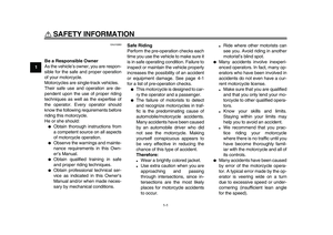
Rebound damping force
To increase the rebound damping force
and thereby harden the rebound damp-
ing, turn the adjusting knob in direction
Damping setting:
Minimum (soft):
1
Standard:
2
Maximum (hard):
4
1. Spring preload adjusting ring
2. Special wrench
3. Position indicator
(a) (b)3
1
2
1 2 3 4 5 6 7 8 9
Spring preload setting:
Minimum (soft):
1
Standard:
5
Maximum (hard):
9
1. Rebound damping force adjusting knob
1
(a)
(b)
✼✥✯✣✲� ✤✬�
���
�
����������������
Page 36 of 96
. To decrease the rebound damping
force and thereby soften the rebound
damping, turn the adjusting knob in di-
rection (b).
Compression")
INSTRUMENT AND CONTROL FUNCTIONS
3-20
1
2
3
4
5
6
7
8
9
(a). To decrease the rebound damping
force and thereby soften the rebound
damping, turn the adjusting knob in di-
rection (b).
Compression damping force
To increase the compression damping
force and thereby harden the compres-sion damping, turn the adjusting knob
in direction (a). To decrease the com-
pression damping force and thereby
soften the compression damping, turn
the adjusting knob in direction (b).
TIP
To obtain a precise adjustment, it is ad-
visable to check the actual total number
of clicks or turns of each damping force
adjusting mechanism. This adjustment
range may not exactly match the spec-
ifications listed due to small differences
in production.
WARNING
EWA10221
This shock absorber assembly con-
tains highly pressurized nitrogen
gas. Read and understand the fol-
lowing information before handlingthe shock absorber assembly.
�
Do not tamper with or attempt to
open the cylinder assembly.
�
Do not subject the shock ab-
sorber assembly to an open
flame or other high heat source.
This may cause the unit to ex-
plode due to excessive gas
pressure.
�
Do not deform or damage the
cylinder in any way. Cylinder
damage will result in poor
damping performance.
�
Do not dispose of a damaged or
worn-out shock absorber as-
sembly yourself. Take the shock
absorber assembly to a Yamaha
dealer for any service.
Rebound damping setting:
Minimum (soft):
20 clicks in direction (b)*
Standard:
12 clicks in direction (b)*
Maximum (hard):
3 clicks in direction (b)*
* With the adjusting knob fully turned in
direction (a)
1. Compression damping force adjusting
knob
1
(a)
(b)
Compression damping setting:
Minimum (soft):
12 clicks in direction (b)*
Standard:
11 clicks in direction (b)*
Maximum (hard):
1 clicks in direction (b)*
* With the adjusting knob fully turned in
direction (a)
✼✥✯✣✲� ✥✣ �
���
�
����������������
Page 37 of 96

INSTRUMENT AND CONTROL FUNCTIONS
3-21
2
34
5
6
7
8
9
EAU15140
Luggage strap holders
There are four luggage strap holders
below the passenger seat, two of which
can be turned out for easier access.
EAU15303
Sidestand
The sidestand is located on the left side
of the frame. Raise the sidestand or
lower it with your foot while holding the
vehicle upright.
TIP
The built-in sidestand switch is part of
the ignition circuit cut-off system, which
cuts the ignition in certain situations.
(See page 3-22 for an explanation of
the ignition circuit cut-off system.)
WARNING
EWA10240
The vehicle must not be ridden with
the sidestand down, or if the side-
stand cannot be properly moved up
(or does not stay up), otherwise the
sidestand could contact the ground
and distract the operator, resulting
in a possible loss of control.
Yamaha’s ignition circuit cut-off
system has been designed to assist
the operator in fulfilling the respon-
sibility of raising the sidestand be-
fore starting off. Therefore, check
this system regularly as described
below and have a Yamaha dealer re-pair it if it does not function proper-
ly.
1. Luggage strap holder
1
✼✥✯✣✲� ✥✤ �
���
�
����������������
Page 38 of 96
INSTRUMENT AND CONTROL FUNCTIONS
3-22
1
2
3
4
5
6
7
8
9
EAU44892
Ignition circuit cut-off system
The ignition circuit cut-off system (com-
prising the sidestand switch, clutch
switch and neutral switch) has the fol-
lowing functions.
�
It prevents starting when the trans-
mission is in gear and the side-
stand is up, but the clutch lever is
not pulled.
�
It prevents starting when the trans-
mission is in gear and the clutch le-
ver is pulled, but the sidestand is
still down.
�
It cuts the running engine when the
transmission is in gear and the sid-
estand is moved down.
Periodically check the operation of the
ignition circuit cut-off system according
to the following procedure.
✼✥✯✣✲� ✥✥ �
���
�
����������������
Page 39 of 96

INSTRUMENT AND CONTROL FUNCTIONS
3-23
2
34
5
6
7
8
9
With the engine turned off:
1. Move the sidestand down.
2. Make sure that the engine stop switch is set to “
3. Turn the key on.
4. Shift the transmission into the neutral position.
5. Push the start switch.
Does the engine start?
With the engine still running:
6. Move the sidestand up.
7. Keep the clutch lever pulled.
8. Shift the transmission into gear.
9. Move the sidestand down.
Does the engine stall?
After the engine has stalled:
10. Move the sidestand up.
11. Keep the clutch lever pulled.
12. Push the start switch.
Does the engine start?
The system is OK. The motorcycle can be ridden.The neutral switch may not be working correctly.
The motorcycle should not be ridden until
checked by a Yamaha dealer.
The sidestand switch may not be working correctly.
The motorcycle should not be ridden until
checked by a Yamaha dealer.
The clutch switch may not be working correctly.
The motorcycle should not be ridden until
checked by a Yamaha dealer.
YES NO YES NO YES NO
If a malfunction is noted, have a Yamaha
dealer check the system before riding.
WARNING
”.
✼✥✯✣✲� ✥✦ �
���
�
����������������
Page 40 of 96

4-1
1
2
3
4
5
6
7
8
9
FOR YOUR SAFETY – PRE-OPERATION CHECKS
EAU15596
Inspect your vehicle each time you use it to make sure the vehicle is in safe operating condition. Always follow the inspection
and maintenance procedures and schedules described in the Owner’s Manual.
WARNING
EWA11151
Failure to inspect or maintain the vehicle properly increases the possibility of an accident or equipment damage.
Do not operate the vehicle if you find any problem. If a problem cannot be corrected by the procedures provided in
this manual, have the vehicle inspected by a Yamaha dealer.
Before using this vehicle, check the following points:
ITEM CHECKS PAGE
Fuel
�
Check fuel level in fuel tank.
�
Refuel if necessary.
�
Check fuel line for leakage.
�
Check the fuel tank breather/overflow hose for obstructions, cracks or damage,
and check the hose connection.3-14, 3-15
Engine oil
�
Check oil level in engine.
�
If necessary, add recommended oil to specified level.
�
Check vehicle for oil leakage.6-9
Coolant
�
Check coolant level in reservoir.
�
If necessary, add recommended coolant to specified level.
�
Check cooling system for leakage.6-12
Front brake
�
Check operation.
�
If soft or spongy, have Yamaha dealer bleed hydraulic system.
�
Check brake pads for wear.
�
Replace if necessary.
�
Check fluid level in reservoir.
�
If necessary, add recommended brake fluid to specified level.
�
Check hydraulic system for leakage.6-22
✼✥✯✣✲� ✤ �
���
�
����������������