Page 49 of 72

PERIODIC MAINTENANCE AND ADJUSTMENT
7-13
2
3
4
5
6
78
9 sively worn tires decreases
riding stability and can lead to
loss of control.
�
The replacement of all
wheel-and brake-related parts,
including the tires, should be
left to a Yamaha dealer, who has
the necessary professional
knowledge and experience.
�
It is not recommended to patch
a punctured tube. If unavoid-
able, however, patch the tube
very carefully and replace it as
soon as possible with a
high-quality product.
EAU21940
Spoke wheels
To maximize the performance, durabil-
ity, and safe operation of your motorcy-
cle, note the following points regarding
the specified wheels.
�
The wheel rims should be checked
for cracks, bends or warpage, and
the spokes for looseness or dam-
age before each ride. If any dam-
age is found, have a Yamaha
dealer replace the wheel. Do not
attempt even the smallest repair to
the wheel. A deformed or cracked
wheel must be replaced.
�
The wheel should be balanced
whenever either the tire or wheel
has been changed or replaced. An
unbalanced wheel can result in
poor performance, adverse han-
dling characteristics, and a short-
ened tire life.
�
Ride at moderate speeds after
changing a tire since the tire sur-
face must first be “broken in” for it
to develop its optimal characteris-
tics.
EAU22120
Adjusting the brake lever free
play
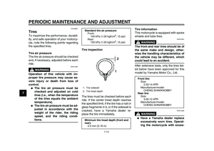
The brake lever free play should mea-
sure 10.0–20.0 mm (0.39–0.79 in) as
shown. Periodically check the brake le-
ver free play and, if necessary, adjust it
as follows.
1. Loosen the locknut at the brake le-
ver.
2. To increase the brake lever free
play, turn the adjusting bolt in di-
rection (a). To decrease the brake
lever free play, turn the adjusting
bolt in direction (b).
1. Brake lever free play
2. Locknut
3. Adjusting bolt
1
2
3
(a)
(b)
Page 50 of 72

PERIODIC MAINTENANCE AND ADJUSTMENT
7-14
1
2
3
4
5
6
7
8
9
3. If the specified brake lever free
play could be obtained as de-
scribed above, tighten the locknut
and skip the rest of the procedure,
otherwise proceed as follows.
4. Fully turn the adjusting bolt at the
brake lever in direction (a) to loos-
en the brake cable.
5. Loosen the locknut at the brake
shoe plate.
6. To increase the brake lever free
play, turn the adjusting nut in direc-
tion (a). To decrease the brake le-
ver free play, turn the adjusting nut
in direction (b).
7. Tighten the locknut at the brakeshoe plate and at the brake lever.
EAU39812
Adjusting the brake pedal free
play
The brake pedal free play should mea-
sure 10.0–20.0 mm (0.39–0.79 in) at
the brake pedal end as shown. Period-
ically check the brake pedal free play
and, if necessary, adjust it as follows.
To increase the brake pedal free play,
turn the adjusting nut at the brake rod in
direction (a). To decrease the brake
pedal free play, turn the adjusting nut in
direction (b).
1. Locknut
2. Adjusting nut
12
(a)
(b)
1. Brake pedal free play
1
Page 51 of 72
PERIODIC MAINTENANCE AND ADJUSTMENT
7-15
2
3
4
5
6
78
9
WARNING
EWA10680
�
After adjusting the drive chain
slack or removing and installing
the rear wheel, always check the
brake pedal free play.
�
If proper adjustment cannot be
obtained as described, have a
Yamaha dealer make this ad-
justment.
�
After adjusting the brake pedal
free play, check the operation of
the brake light.
EAU41052
Checking the front and rear
brake shoes
The front and rear brake shoes must be
checked for wear at the intervals spec-
ified in the periodic maintenance and
lubrication chart.
TIP
The wheels must be removed to check
brake shoe lining thickness.
�
To remove the front wheel: See
page 7-22.
�
To remove the rear wheel: See
page 7-24.
FrontRear
If the lining thickness of a brake shoe is
less than 1.5 mm (0.06 in), have a
Yamaha dealer replace the brake
shoes as a set.
TIP
Be sure to measure the brake lining at
the thinnest portion.
1. Brake pedal free play adjusting nut
1
(a)
(b)
Page 52 of 72

PERIODIC MAINTENANCE AND ADJUSTMENT
7-16
1
2
3
4
5
6
7
8
9
EAU22760
Drive chain slack
The drive chain slack should be
checked before each ride and adjusted
if necessary.
EAU22773
To check the drive chain slack
1. Place the motorcycle on the side-
stand.
TIP
When checking and adjusting the drive
chain slack, there should be no weight
on the motorcycle.
2. Shift the transmission into the neu-
tral position.
3. Move the rear wheel by pushing
the motorcycle to locate the tight-
est portion of the drive chain, and
then measure the drive chain slack
as shown.4. If the drive chain slack is incorrect,
adjust it as follows.
EAU40111
To adjust the drive chain slack
1. Loosen the brake pedal free play
adjusting nut, axle nut, and locknut
at each end of the swingarm.2. To tighten the drive chain, turn the
drive chain slack adjusting nut at
each end of the swingarm in direc-
tion (a). To loosen the drive chain,
turn the adjusting nut at each end
of the swingarm in direction (b),
and then push the rear wheel for-
ward.
NOTICE:
Improper drive
chain slack will overload the en-
gine as well as other vital parts
of the motorcycle and can lead
to chain slippage or breakage.
To prevent this from occurring,
keep the drive chain slack with-
Drive chain slack:
40.0–53.0 mm (1.57–2.09 in)
1. Drive chain slack
1
1. Brake pedal free play adjusting nut
2. Locknut
3. Drive chain slack adjusting nut
4. Wheel axle
2
14 3
Page 53 of 72
![YAMAHA PW80 2010 Owners Manual
PERIODIC MAINTENANCE AND ADJUSTMENT
7-17
2
3
4
5
6
78
9 in the specified limits.
[ECA10571]
TIP
Using the alignment marks on each
side of the swingarm, make sure that
both adjusting nuts ar](/manual-img/51/51154/w960_51154-52.png "YAMAHA PW80 2010 Owners Manual
PERIODIC MAINTENANCE AND ADJUSTMENT
7-17
2
3
4
5
6
78
9 in the specified limits.
[ECA10571]
TIP
Using the alignment marks on each
side of the swingarm, make sure that
both adjusting nuts ar")
PERIODIC MAINTENANCE AND ADJUSTMENT
7-17
2
3
4
5
6
78
9 in the specified limits.
[ECA10571]
TIP
Using the alignment marks on each
side of the swingarm, make sure that
both adjusting nuts are in the same po-
sition for proper wheel alignment.
3. Tighten both locknuts and the axle
nut to the specified torques.4. Adjust the brake pedal free play.
(See page 7-14.)
EAU23013
Cleaning and lubricating the
drive chain
The drive chain must be cleaned and
lubricated at the intervals specified in
the periodic maintenance and lubrica-
tion chart, otherwise it will quickly wear
out, especially when riding in dusty or
wet areas. Service the drive chain as
follows.
NOTICE
ECA10581
The drive chain must be lubricated
after washing the motorcycle and
riding in the rain.
1. Remove all dirt and mud from the
drive chain with a brush or cloth.
TIP
For a thorough cleaning, have a
Yamaha dealer remove the drive chain
and soak it in solvent.
2. Spray Yamaha Chain and Cable
Lube or a high-quality spray-type
drive chain lubricant on both sides
and on the middle of the chain,
making sure that all side plates and
rollers have been sufficiently oiled.
1. Alignment marks
2. Drive chain slack adjusting nut
3. Locknut
4. Washer
5. Axle nut
5
42
1
(a)
(b)3
Tightening torques:
Locknut:
6.5 Nm (0.7 m·kgf, 4.7 ft·lbf)
Axle nut:
60 Nm (6.0 m·kgf, 43.4 ft·lbf)
Page 54 of 72

PERIODIC MAINTENANCE AND ADJUSTMENT
7-18
1
2
3
4
5
6
7
8
9
EAU41842
Checking and lubricating the
cables
The operation of all control cables and
the condition of the cables should be
checked before each ride, and the ca-
bles and cable ends should be lubricat-
ed if necessary. If a cable is damaged
or does not move smoothly, have a
Yamaha dealer check or replace it.
WARNING! Damage to the outer
housing of cables may result in in-
ternal rusting and cause interfer-
ence with cable movement. Replace
damaged cables as soon as possi-
ble to prevent unsafe condi-
tions.
[EWA10711]
EAU23111
Checking and lubricating the
throttle grip and cable
The operation of the throttle grip should
be checked before each ride. In addi-
tion, the cable should be lubricated at
the intervals specified in the periodic
maintenance chart.
EAU23120
Adjusting the Autolube pump
The Autolube pump is a vital and so-
phisticated component of the engine,
which must be adjusted by a Yamaha
dealer at the intervals specified in the
periodic maintenance and lubrication
chart.
Recommended lubricant:
Yamaha Chain and Cable Lube or
4-stroke engine oil
Page 55 of 72

PERIODIC MAINTENANCE AND ADJUSTMENT
7-19
2
3
4
5
6
78
9
EAU43622
Checking and lubricating the
brake lever
The operation of the brake lever should
be checked before each ride, and the
lever pivot should be lubricated if nec-
essary.
EAU23182
Checking and lubricating the
brake pedal
The operation of the brake pedal
should be checked before each ride,
and the pedal pivot should be lubricat-
ed if necessary.
EAU23202
Checking and lubricating the
sidestand
The operation of the sidestand should
be checked before each ride, and the
sidestand pivot and metal-to-metal
contact surfaces should be lubricated if
necessary.
WARNING
EWA10731
If the sidestand does not move up
and down smoothly, have a Yamaha
dealer check or repair it. Otherwise,
the sidestand could contact the
ground and distract the operator, re-
sulting in a possible loss of control.
Recommended lubricant:
Lithium-soap-based grease
Recommended lubricant:
Lithium-soap-based grease
Recommended lubricant:
Lithium-soap-based grease
Page 56 of 72

PERIODIC MAINTENANCE AND ADJUSTMENT
7-20
1
2
3
4
5
6
7
8
9
EAU23272
Checking the front fork
The condition and operation of the front
fork must be checked as follows at the
intervals specified in the periodic main-
tenance and lubrication chart.
To check the condition
Check the inner tubes for scratches,
damage and excessive oil leakage.
To check the operation
1. Place the vehicle on a level sur-
face and hold it in an upright posi-
tion.
WARNING! To avoid injury,
securely support the vehicle so
there is no danger of it falling
over.
[EWA10751]
2. While applying the front brake,
push down hard on the handlebars
several times to check if the front
fork compresses and rebounds
smoothly.
NOTICE
ECA10590
If any damage is found or the front
fork does not operate smoothly,
have a Yamaha dealer check or re-
pair it.
EAU23283
Checking the steering
Worn or loose steering bearings may
cause danger. Therefore, the operation
of the steering must be checked as fol-
lows at the intervals specified in the pe-
riodic maintenance and lubrication
chart.
1. Place a stand under the engine to
raise the front wheel off the
ground. (See page 7-21 for more
information.)
WARNING! To
avoid injury, securely support
the vehicle so there is no danger
of it falling over.
[EWA10751]
2. Hold the lower ends of the front
fork legs and try to move them for-
ward and backward. If any free
play can be felt, have a Yamaha
dealer check or repair the steering.