Page 41 of 72

PERIODIC MAINTENANCE AND ADJUSTMENT
7-5
2
3
4
5
6
78
9
EAU19603
Checking the spark plug
The spark plug is an important engine
component, which is easy to check.
Since heat and deposits will cause any
spark plug to slowly erode, the spark
plug should be removed and checked
in accordance with the periodic mainte-
nance and lubrication chart. In addition,
the condition of the spark plug can re-
veal the condition of the engine.
To remove the spark plug
1. Remove the spark plug cap.
2. Remove the spark plug as shown,
with the spark plug wrench includ-
ed in the owner’s tool kit.
To check the spark plug
1. Check that the porcelain insulator
around the center electrode of the
spark plug is a medium-to-light tan
(the ideal color when the vehicle is
ridden normally).
TIP
If the spark plug shows a distinctly dif-
ferent color, the engine could be oper-
ating improperly. Do not attempt to
diagnose such problems yourself. In-
stead, have a Yamaha dealer check
the vehicle.
2. Check the spark plug for elec-
trode erosion and excessive car-
bon or other deposits, and replaceit if necessary.
To install the spark plug
1. Measure the spark plug gap with a
wire thickness gauge and, if nec-
essary, adjust the gap to specifica-
tion.
2. Clean the surface of the spark plug
gasket and its mating surface, and
then wipe off any grime from the
1. Spark plug cap
1
1. Spark plug wrench
1
Specified spark plug:
PW80
NGK/BPR6HS
PW80Z NGK/BP6HS
DENSO/W20FP
1. Spark plug gap
Spark plug gap:
0.6–0.7 mm (0.024–0.028 in)
1
Page 42 of 72

PERIODIC MAINTENANCE AND ADJUSTMENT
7-6
1
2
3
4
5
6
7
8
9
spark plug threads.
3. Install the spark plug with the
spark plug wrench, and then tight-
en it to the specified torque.
TIP
If a torque wrench is not available when
installing a spark plug, a good estimate
of the correct torque is 1/4–1/2 turn
past finger tight. However, the spark
plug should be tightened to the speci-
fied torque as soon as possible.
4. Install the spark plug cap.
EAU41102
Removing the power
reduction plate
To obtain full engine performance ca-
pability, removing the power reduction
plate is required.
1. Remove the exhaust manifold by
removing the bolts.
WARNING!
Always let the exhaust system
cool prior to touching exhaust
components.
[EWA14581]
2. Remove the gasket.
3. Remove the power reduction
plate.
TIP
Store the power reduction plate with the
Owner’s Manual so that it is readily
available whenever you want to reduce
the engine power.
4. Install the exhaust manifold by in-
stalling the bolts.
Tightening torque:
Spark plug:
25 Nm (2.5 m·kgf, 18.1 ft·lbf)
1. Exhaust manifold bolt
1
1. Exhaust manifold
2. Gasket
3. Power reduction plate
Tightening torque:
Exhaust manifold bolt:
18 Nm (1.8 m·kgf, 13.0 ft·lbf)
2 13
Page 43 of 72

PERIODIC MAINTENANCE AND ADJUSTMENT
7-7
2
3
4
5
6
78
9
EAU19943
Transmission oil
The transmission oil level should be
checked before each ride. In addition,
the transmission oil must be changed
at the intervals specified in the periodic
maintenance and lubrication chart.
To check the transmission oil level
1. Place the vehicle on a level sur-
face and hold it in an upright posi-
tion.
TIP
Make sure that the vehicle is positionedstraight up when checking the oil level.
A slight tilt to the side can result in a
false reading.
2. Wait a few minutes until the oil set-
tles, remove the oil filler cap, wipe
the dipstick clean, insert it back
into the oil filler hole (without
screwing it in), and then remove it
again to check the oil level.
TIP
The transmission oil should be be-
tween the minimum and maximum lev-
el marks.
3. If the oil is below the minimum lev-
el mark, add sufficient oil of the
recommended type to raise it to
the correct level.
4. Insert the dipstick into the oil filler
hole, and then tighten the oil filler
cap.
To change the transmission oil
1. Place an oil pan under the trans-
mission to collect the used oil.
2. Remove the oil filler cap and drain
bolt to drain the oil from the trans-
mission.
3. Install the transmission oil drain
bolt, and then tighten it to the spec-
ified torque.
4. Refill with the specified amount of
the recommended transmission
oil, and then install and tighten the
oil filler cap.
1. Transmission oil filler cap
2. Dipstick
3. Maximum level mark
4. Minimum level mark
2
3
41
1
1. Transmission oil drain bolt
Tightening torque:
Transmission oil drain bolt:
20 Nm (2.0 m·kgf, 14.5 ft·lbf)
1
Page 44 of 72
, do
not mix any chemi")
PERIODIC MAINTENANCE AND ADJUSTMENT
7-8
1
2
3
4
5
6
7
8
9
NOTICE
ECA10452
�
In order to prevent clutch slip-
page (since the transmission oil
also lubricates the clutch), do
not mix any chemical additives.
Do not use oils with a diesel
specification of “CD” or oils of a
higher quality than specified. In
addition, do not use oils labeled
“ENERGY CONSERVING II” or
higher.
�
Make sure that no foreign mate-
rial enters the transmission.
5. Start the engine, and then let it idle
for several minutes while checking
the transmission for oil leakage. If
oil is leaking, immediately turn the
engine off and check for the cause.
EAU41162
Cleaning the air filter element
The air filter element should be cleaned
at the intervals specified in the periodic
maintenance and lubrication chart.
Clean the air filter element more fre-
quently if you are riding in unusually
wet or dusty areas.
1. Remove the air filter case cover by
removing the screws.
2. Pull the air filter element out.3. Remove the sponge material from
the air filter case cover, clean it
with solvent, and then squeeze the
remaining solvent out.
Recommended transmission oil:
See page 9-1.
Oil change quantity:
0.65 L (0.69 US qt, 0.57 Imp.qt)
1. Air filter case cover
2. Screw
2
2
1
1. Sponge material
2. Air filter case cover
1
2
Page 45 of 72

PERIODIC MAINTENANCE AND ADJUSTMENT
7-9
2
3
4
5
6
78
9
4. Apply oil of the recommended type
to the entire surface of the sponge
material, and then squeeze the ex-
cess oil out.
TIP
The sponge material should be wet but
not dripping.
5. Install the sponge material onto
the air filter case cover.
6. Insert the air filter element into the
air filter case.
NOTICE:
Make sure
that the air filter element is prop-
erly seated in the air filter case.
The engine should never be op-erated without the air filter ele-
ment installed, otherwise the
piston(s) and/or cylinder(s) may
become excessively worn.
[ECA10481]
7. Install the air filter case cover by in-
stalling the screws.
EAU41232
Cleaning the spark arrester
The spark arrester should be cleaned
at the intervals specified in the periodic
maintenance and lubrication chart.
WARNING
EWA10980
�
Always let the exhaust system
cool prior to touching exhaust
components.
�
Do not start the engine when
cleaning the exhaust system.
1. Remove the tailpipe by removing
the bolt, and then pulling it out of
the muffler.
2. Tap the tailpipe lightly, and then
use a wire brush to remove any
Recommended oil:
Yamaha foam air filter oil or other
quality foam air filter oil
1. Bolt
1
Page 46 of 72

PERIODIC MAINTENANCE AND ADJUSTMENT
7-10
1
2
3
4
5
6
7
8
9
carbon deposits from the spark ar-
rester portion of the tailpipe and in-
side of the tailpipe housing.
3. Insert the tailpipe into the muffler,
and then install and tighten the bolt
to the specified torque.
TIP
Make sure to align the bolt hole when
inserting the tailpipe.
EAU39930
Adjusting the carburetor
The carburetor is an important part of
the engine and requires very sophisti-
cated adjustment. Therefore, most car-
buretor adjustments should be left to a
Yamaha dealer, who has the neces-
sary professional knowledge and expe-
rience. The adjustment described in the
following section, however, may be ser-
viced by the owner as part of routine
maintenance.
NOTICE
ECA10550
The carburetor has been set and ex-
tensively tested at the Yamaha fac-
tory. Changing these settings
without sufficient technical knowl-
edge may result in poor perfor-
mance of or damage to the engine.
EAU21340
Adjusting the engine idling
speed
The engine idling speed must be
checked and, if necessary, adjusted as
follows at the intervals specified in the
periodic maintenance and lubrication
chart.
The engine should be warm before
making this adjustment.
TIP
�
The engine is warm when it quickly
responds to the throttle.
�
A diagnostic tachometer is needed
to make this adjustment.
1. Attach the tachometer to the spark
plug lead.
2. Check the engine idling speed
and, if necessary, adjust it to spec-
ification by turning the throttle stop
screw. To increase the engine
idling speed, turn the screw in di-
rection (a). To decrease the en-
gine idling speed, turn the screw in
direction (b).
1. Tailpipe
2. Spark arrester
3. Bolt
Tightening torque:
Tailpipe bolt:
7.5 Nm (0.8 m·kgf, 5.5 ft·lbf)
23
1
Page 47 of 72
PERIODIC MAINTENANCE AND ADJUSTMENT
7-11
2
3
4
5
6
78
9
TIP
If the specified idling speed cannot be
obtained as described above, have a
Yamaha dealer make the adjustment.
EAU21370
Adjusting the throttle cable
free play
The throttle cable free play should mea-
sure 3.0–5.0 mm (0.12–0.20 in) at the
throttle grip. Periodically check the
throttle cable free play and, if neces-
sary, adjust it as follows.
TIP
The engine idling speed must be cor-
rectly adjusted before checking and ad-
justing the throttle cable free play.
1. Loosen the locknut.
2. To increase the throttle cable free
play, turn the adjusting nut in direc-
tion (a). To decrease the throttlecable free play, turn the adjusting
nut in direction (b).
3. Tighten the locknut.
1. Throttle stop screw
Engine idling speed:
1650–1750 r/min
1
(a) (b)
1. Throttle cable free play1
1. Locknut
2. Adjusting nut
1
2
(a)
(b)
Page 48 of 72

PERIODIC MAINTENANCE AND ADJUSTMENT
7-12
1
2
3
4
5
6
7
8
9
EAU39821
Tires
To maximize the performance, durabil-
ity, and safe operation of your motorcy-
cle, note the following points regarding
the specified tires.
Tire air pressure
The tire air pressure should be checked
and, if necessary, adjusted before each
ride.
WARNING
EWA14381
Operation of this vehicle with im-
proper tire pressure may cause se-
vere injury or death from loss of
control.
�
The tire air pressure must be
checked and adjusted on cold
tires (i.e., when the temperature
of the tires equals the ambient
temperature).
�
The tire air pressure must be ad-
justed in accordance with the
weight of the rider, the riding
speed, and the riding condi-
tions.Tire inspection
The tires must be checked before each
ride. If the center tread depth reaches
the specified limit, if the tire has a nail or
glass fragments in it, or if the sidewall is
cracked, have a Yamaha dealer re-
place the tire immediately.
Tire information
This motorcycle is equipped with spoke
wheels and tube tires.
WARNING
EWA10461
The front and rear tires should be of
the same make and design, other-
wise the handling characteristics of
the vehicle may be different, which
could lead to an accident.
After extensive tests, only the tires list-
ed below have been approved for this
model by Yamaha Motor Co., Ltd.
WARNING
EWA14390
�
Have a Yamaha dealer replace
excessively worn tires. Operat-
ing the motorcycle with exces-
Standard tire air pressure:
Front:
100 kPa (1.00 kgf/cm 2
, 15 psi)
Rear:
100 kPa (1.00 kgf/cm
2
, 15 psi)
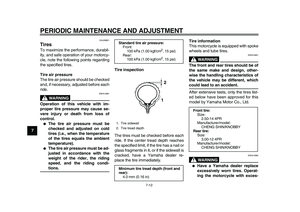
1. Tire sidewall
2. Tire tread depth
Minimum tire tread depth (front and
rear):
4.0 mm (0.16 in)
12
Front tire:
Size:
2.50-14 4PR
Manufacturer/model:
CHENG SHIN/KNOBBY
Rear tire:
Size:
3.00-12 4PR
Manufacturer/model:
CHENG SHIN/KNOBBY