Page 120 of 168
![YAMAHA GRIZZLY 700 2010 Owners Manual 8-30
85. Refill with the recommended differential gear
oil to the brim of the filler hole as shown.
NOTICE: Be sure no foreign material en-
ters the differential gear case.
[ECB00411]
6. Install the](/manual-img/51/50473/w960_50473-119.png "YAMAHA GRIZZLY 700 2010 Owners Manual 8-30
85. Refill with the recommended differential gear
oil to the brim of the filler hole as shown.
NOTICE: Be sure no foreign material en-
ters the differential gear case.
[ECB00411]
6. Install the")
8-30
85. Refill with the recommended differential gear
oil to the brim of the filler hole as shown.
NOTICE: Be sure no foreign material en-
ters the differential gear case.
[ECB00411]
6. Install the oil filler bolt, and then tighten it to the
specified torque.7. Check the differential gear case for oil leak-
age. If oil is leaking, check for the cause.
EBU23470Coolant The coolant level should be checked before each
ride. In addition, the coolant must be changed at
the intervals specified in the periodic maintenance
and lubrication chart.EBU27124To check the coolant level
1. Place the ATV on a level surface.TIPThe coolant level must be checked on a cold en-
gine since the level varies with engine tempera-
ture.2. Check the coolant level in the coolant reser-
voir.
1. Differential gear oil
2. Differential gear oil filler bolt
3. Correct oil levelRecommended differential gear oil:
See page 10-1.
Tightening torque:
Differential gear oil filler bolt:
23 Nm (2.3 m·kgf, 17 ft·lbf)
U43P62E0.book Page 30 Tuesday, February 17, 2009 1:09 PM
Page 121 of 168

4. Remove the coolant reservoir cap")
8-31
8
TIPThe coolant should be between the minimum and
maximum level marks.3. If the coolant is at or below the minimum level
mark, remove panel D. (See page 8-8.)
4. Remove the coolant reservoir cap, add cool-
ant or distilled water to the maximum level
mark, install the reservoir cap, and then install
the panel. NOTICE: If coolant is not avail-
able, use distilled water or soft tap water
instead. Do not use hard water or salt wa-
ter since they are harmful to the engine. Ifwater has been used instead of coolant, re-
place it with coolant as soon as possible,
otherwise the cooling system will not be
protected against frost and corrosion. If
water has been added to the coolant, have
a Yamaha dealer check the antifreeze con-
tent of the coolant as soon as possible,
otherwise the effectiveness of the coolant
will be reduced.
[ECB01011]
1. Maximum level mark
2. Minimum level mark
1. Coolant reservoir cap
2. Maximum level mark
3. Minimum level mark
U43P62E0.book Page 31 Tuesday, February 17, 2009 1:09 PM
Page 122 of 168
8-32
8
TIP�The radiator fan is automatically switched on or
off according to the coolant temperature in the
radiator.�If the engine overheats, see page 8-63 for fur-
ther instructions.EBU27762To change the coolant
WARNING
EWB01890Wait for the engine and radiator to cool before
removing the radiator cap. You could be
burned by hot fluid and steam blown out under
pressure. Always place a thick rag over the cap
when opening. Allow any remaining pressure
to escape before completely removing the cap.1. Place the ATV on a level surface.
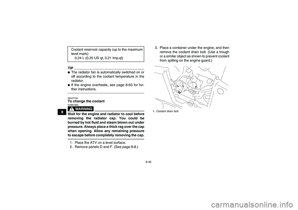
2. Remove panels D and F. (See page 8-8.)3. Place a container under the engine, and then
remove the coolant drain bolt. (Use a trough
or a similar object as shown to prevent coolant
from spilling on the engine guard.) Coolant reservoir capacity (up to the maximum
level mark):
0.24 L (0.25 US qt, 0.21 Imp.qt)
1. Coolant drain bolt
U43P62E0.book Page 32 Tuesday, February 17, 2009 1:09 PM
Page 124 of 168

8-34
810. Connect the coolant reservoir hose.
11. Pour the recommended coolant into the radia-
tor until it is full.
12. Pour the recommended coolant into the reser-
voir to the maximum level mark, and then in-
stall the reservoir cap. NOTICE: Mix
antifreeze with distilled water only. Howev-
er, if distilled water is not available, soft
water may be used for refilling. Do not use
hard water or salt water since they are
harmful to the engine.
[ECB00991]
13. Loosen the water pump air bleed bolt, without
removing it, to allow all of the air to escape
from the air bleed bolt hole.
14. When coolant begins to flow out of the bolt
hole, tighten the water pump air bleed bolt to
the specified torque.
15. Remove panel E. (See page 8-8.)
16. Loosen the clamp screw, and then remove the
V-belt cooling duct. Antifreeze/water mixture ratio:
1:1
Recommended antifreeze:
High-quality ethylene glycol antifreeze con-
taining corrosion inhibitors for aluminum en-
gines
Coolant quantity:
Radiator capacity (including all routes):
1.99 L (2.10 US qt, 1.75 Imp.qt)
Coolant reservoir capacity (up to the maxi-
mum level mark):
0.24 L (0.25 US qt, 0.21 Imp.qt)1. Water pump air bleed boltTightening torque:
Water pump air bleed bolt:
10 Nm (1.0 m·kgf, 7.2 ft·lbf)
U43P62E0.book Page 34 Tuesday, February 17, 2009 1:09 PM
Page 125 of 168
8-35
8 17. Loosen the cylinder head air bleed bolt, with-
out removing it, to allow all of the air to escape
from the air bleed bolt hole.18. When coolant begins to flow out of the bolt
hole, tighten the cylinder head air bleed bolt to
the specified torque.
19. Start the engine and let it idle for ten minutes.
20. Rev the engine five times.
21. Pour the recommended coolant into the radia-
tor until it is full.
1. V-belt cooling duct
2. Clamp screw
1. Cylinder head air bleed boltTightening torque:
Cylinder head air bleed bolt:
10 Nm (1.0 m·kgf, 7.2 ft·lbf)
U43P62E0.book Page 35 Tuesday, February 17, 2009 1:09 PM
Page 126 of 168

8-36
822. Stop the engine and allow it to cool. If the cool-
ant level has dropped after the engine has
cooled, add sufficient coolant until it reaches
the top of the radiator, and then install the ra-
diator cap.
23. Start the engine, and then check for coolant
leakage.
TIPIf any leakage is found, have a Yamaha dealer
check the cooling system.24. Install the V-belt cooling duct, and then tighten
the clamp screw.
25. Install the panels.EBU27805Cleaning the air filter element The air filter element should be cleaned at the in-
tervals specified in the periodic maintenance and
lubrication chart. Clean or, if necessary, replace
the air filter element more frequently if you are
riding in unusually wet or dusty areas.TIPThere are two check hoses at the bottom of the air
filter case, which are located behind panels D and
E. (See page 8-8 for an explanation on removingthe panels.) Check the hoses periodically and, if
dust or water collects in them, empty them and
clean the air filter element and air filter case.
1. Air filter case check hose
U43P62E0.book Page 36 Tuesday, February 17, 2009 1:09 PM
Page 128 of 168

8-38
85. Clean the mesh with solvent, and then wipe
the solvent off.
6. Wash the sponge material gently, but thor-
oughly, in solvent. WARNING! Always use
parts cleaning solvent to clean the sponge
material. Never use low-flash-point sol-
vents or gasoline to clean the sponge ma-
terial because the engine could catch fire
or explode.
[EWB01941]
7. Squeeze the excess solvent out of the sponge
material and let it dry. NOTICE: Do not twist
the sponge material when squeezing it.
[ECB00441]
8. Check the sponge material and replace it if
damaged.
9. Apply Yamaha foam air filter oil or other qual-
ity foam air filter oil to the sponge material.TIPThe sponge material should be wet but not drip-
ping.10. Install the mesh and the sponge material into
the air filter case. NOTICE: Make sure that
the air filter element is properly seated in
the air filter case. Never operate the engine
with the air filter element removed. This
will allow unfiltered air to enter the engine,
causing rapid engine wear and possible
1. Sponge material
2. Air filter meshU43P62E0.book Page 38 Tuesday, February 17, 2009 1:09 PM
Page 129 of 168
![YAMAHA GRIZZLY 700 2010 Owners Manual 8-39
8 engine damage. Additionally, operation
without the air filter element will affect the
fuel injection system with subsequent
poor performance and possible engine
overheating.
[ECB00761]
11. Ins](/manual-img/51/50473/w960_50473-128.png "YAMAHA GRIZZLY 700 2010 Owners Manual 8-39
8 engine damage. Additionally, operation
without the air filter element will affect the
fuel injection system with subsequent
poor performance and possible engine
overheating.
[ECB00761]
11. Ins")
8-39
8 engine damage. Additionally, operation
without the air filter element will affect the
fuel injection system with subsequent
poor performance and possible engine
overheating.
[ECB00761]
11. Insert the projections on the air filter case cov-
er into the holders on the air filter case, and
then install the air filter case cover by hooking
the holders onto the cover.
12. Place the hoses in their original position as
shown.13. Install the panel.
TIPThe air filter element should be cleaned every 20–
40 hours. It should be cleaned and lubricated more
often if the ATV is operated in extremely dusty ar-
eas. Each time the air filter element maintenance
is performed, check the air inlet of the air filter case
for obstructions. Check the air filter case rubber
joint to the throttle body and the rubber joint mani-
fold fittings for an air-tight seal. Tighten all fittings
securely to avoid the possibility of unfiltered air en-
tering the engine.1. Hose
1
U43P62E0.book Page 39 Tuesday, February 17, 2009 1:09 PM