Page 25 of 102
Safety information
18
waterways stay open for the enjoyment of a
variety of recreational opportunities.
UF2R71E0.book Page 18 Monday, July 13, 2009 11:28 AM
Page 26 of 102

Description
19
EJU40302
Watercraft glossary
Trolling speed
“Trolling” is the lowest maneuvering speed. You are applying little or no throttle. The watercraft
is down in the water, and there is no wake.
Sub-planing speed
“Sub-planing” is a medium speed. The bow of the watercraft is slightly up from the water sur-
face, but you are still traveling through the water. There is a wake.
Planing speed
“Planing” is a faster speed. The watercraft is more level and is skimming on top of the water.
There is a wake.
Bow
The front end of the watercraft.
Stern
The rear end of the watercraft.
Starboard
The right side of the watercraft when facing forward.
Port
The left side of the watercraft when facing forward.
Bilge water
Water that has collected in the engine compartment.
Yamaha Engine Management System (YEMS)
YEMS is an integrated, computerized management system that controls and adjusts ignition
timing, fuel injection, engine diagnostics, and the off-throttle steering (OTS) system.
UF2R71E0.book Page 19 Monday, July 13, 2009 11:28 AM
Page 27 of 102
Description
20
EJU31011
Location of main components
Exterior
3
4
5
6
10
9
7
8
1
2
1Fuel filler cap (page 46)
2Hood
3Handlebars
4Rear seat (page 39)
5Front seat (page 39)
6Footwell
7Bow eye
8Cooling water pilot outlet (page 28)
9Gunwale
10Sponson
UF2R71E0.book Page 20 Monday, July 13, 2009 11:28 AM
Page 28 of 102
Description
21
23
9
8
5 1
7
6
11
10
4
1Boarding platform
2Electric bilge pilot outlet
3Reboarding grip (page 40)
4Reboarding step (page 40)
5Jet thrust nozzle
6Reverse gate (page 30)
7Ride plate
8Stern drain plug (page 49)
9Stern eye (page 41)
10Speed sensor
11Intake grate
UF2R71E0.book Page 21 Monday, July 13, 2009 11:28 AM
Page 29 of 102
Description
22
1234
675
10
1112 1314 9 8
1Q.S.T.S. selector (page 31)
2Q.S.T.S. selector lock lever (page 31)
3Start switch (page 26)
4Engine shut-off switch (page 26)
5Clip (page 26)
6Engine stop switch (page 26)
7Engine shut-off cord (lanyard) (page 26)
8Dual analog meter unit (page 34)
9Rearview mirror
10Glove compartment (page 42)
11Remote control transmitter (page 24)
12Beverage holder (page 44)
13Shift lever (page 30)
14Throttle lever (page 27)
UF2R71E0.book Page 22 Monday, July 13, 2009 11:28 AM
Page 30 of 102
Description
23
Engine compartment
123
46 5
910
8
7
1Engine cover
2Air filter case
3Water separator (page 29)
4Fuel tank
5Battery (page 56)
6Flushing hose connector
7Electrical box
8Spark plug/Spark plug cap/Ignition coil
9Engine oil filler cap (page 48)
10Dipstick
UF2R71E0.book Page 23 Monday, July 13, 2009 11:28 AM
Page 31 of 102

Control function operation
24
EJU31024
Watercraft control functions EJU41390Remote control transmitter
The Yamaha Security System and Low RPM
Mode settings can be selected by operating
the remote control transmitter. (See page 25
for Yamaha Security System setting proce-
dures and page 32 for Low RPM Mode activa-
tion procedures.)
Since the watercraft is programmed to recog-
nize the internal code from this transmitter
only, the settings can only be selected with
this transmitter.
If you accidentally lose your remote control
transmitter or if it is not operating properly,
contact a Yamaha dealer.
When operating the watercraft, always keep
the transmitter with you, such as by storing itin the transmitter holder in the beverage hold-
er, so that it is not lost.
NOTICE
ECJ00752
�The remote control transmitter is not
completely waterproof. Do not sub-
merge the transmitter or operate it un-
derwater. If the transmitter is
submerged, dry it with a soft, dry cloth,
and then check that it is operating prop-
erly. If the transmitter is not operating
properly, contact a Yamaha dealer.
�Keep the remote control transmitter
away from high temperatures and do not
place it in direct sunlight.
�Do not drop the remote control transmit-
ter, subject it to strong shocks, or place
any heavy items on it.
�Use a soft, dry cloth to clean the remote
control transmitter. Do not use deter-
gent, alcohol, or other chemicals.
�Do not attempt to disassemble the re-
mote control transmitter yourself. Other-
wise, the transmitter may not operate
properly. If the transmitter needs a new
battery, contact a Yamaha dealer. Refer
to local hazardous waste regulations
when disposing of transmitter batteries.
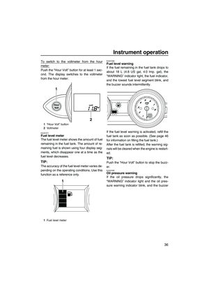
1Remote control transmitter
1Transmitter holder
1
UF2R71E0.book Page 24 Monday, July 13, 2009 11:28 AM
Page 32 of 102

Control function operation
25
EJU31384Yamaha Security System
The Yamaha Security System functions to
help prevent unauthorized use or theft of the
watercraft. The lock and unlock modes of the
security system can be selected by operating
the remote control transmitter that is included
with this watercraft. The engine cannot be
started if the lock mode of the security system
is selected. The engine can only be started if
the unlock mode is selected. (See page 24 for
information on the remote control transmitter.)
TIP:
The Yamaha Security System settings can
only be selected while the engine is stopped.
EJU37412Yamaha Security System settings
The Yamaha Security System settings will be
confirmed by the number of beeps when the
remote control transmitter is operated, and by
the “UNLOCK” indicator light of the dual ana-
log meter unit. (See page 34 for information
on the dual analog meter unit.)
TIP:
�The beeper sounds two times for the nor-
mal operation mode or three times for the
Low RPM Mode. (See page 32 for Low
RPM Mode activation procedures.)
�If the remote control transmitter is operated
while the dual analog meter unit is in the
standby state, the unit will perform the initial
operation, and then the setting is selected.To select the lock mode:
Push the lock button on the remote control
transmitter briefly. The beeper sounds once
and the “UNLOCK” indicator light blinks once,
then goes off. This indicates the lock mode is
selected.
To select the unlock mode:
Push the “L-Mode” (unlock) button on the re-
mote control transmitter briefly. The beeper
sounds two or three times and the “UNLOCK”
indicator light blinks two or three times, then
comes on. This indicates the unlock mode is
selected.
Number of
beepsYamaha Security
System mode“UN-
LOCK” in-
dicator
light
Lock Goes off
Unlock
(normal operation
mode)Comes
on
Unlock
(Low RPM Mode)Comes
on
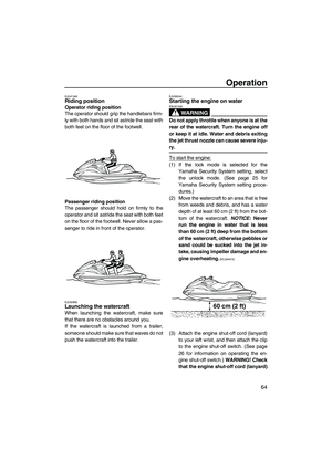
1Lock button
2“UNLOCK” indicator light
1“L-Mode” (unlock) button
2“UNLOCK” indicator light
1
2
L-Mode1
2
UF2R71E0.book Page 25 Monday, July 13, 2009 11:28 AM


2Hood
3Handlebars
4Rear seat (page 39)
5Front seat (page 39)
6Footwell
7Bow eye
8Cooling w")

4Reboarding step (page 40)
5Jet thrust nozzle
6Reverse gate (page 30)
7Ride plate
8Ster")

2Q.S.T.S. selector lock lever (page 31)
3Start switch (page 26)
4Engine shut-off switch (page 26)
5Clip (page 26)
6Engine stop swi")

4Fuel tank
5Battery (page 56)
6Flushing hose connector
7Electrical box
8Spark plug/Spark pl")