Page 105 of 146
8-27
1
2
3
4
5
6
78
9
10
11
9. Loosen the carburetor joint screws.10. Remove the mixing chamber cap.
11. Remove the throttle cable from the throttle
valve, and then remove the throttle cable hold-
er by removing the screws.
1. Mixing chamber cap securing plate
2. Screw
21
1. Joint screw
1
11
1
✦✯��✬�✩✧�✤✲✣ ✥✪ ��
����������������������
Page 107 of 146

8-29
1
2
3
4
5
6
78
9
10
11
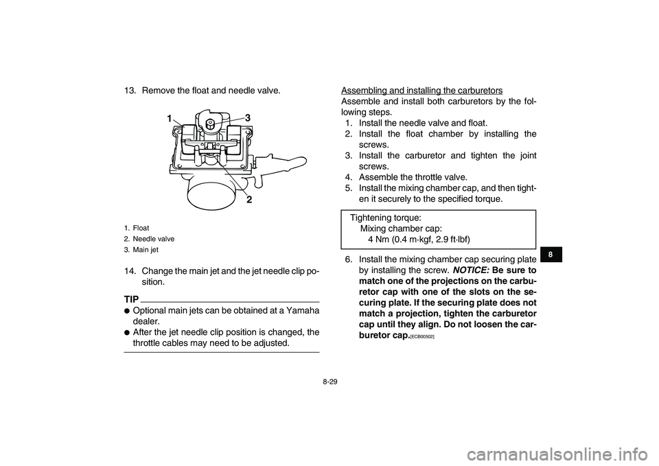
13. Remove the float and needle valve.
14. Change the main jet and the jet needle clip po-
sition.
TIP
�
Optional main jets can be obtained at a Yamaha
dealer.
�
After the jet needle clip position is changed, the
throttle cables may need to be adjusted.Assembling and installing the carburetors
Assemble and install both carburetors by the fol-
lowing steps.
1. Install the needle valve and float.
2. Install the float chamber by installing the
screws.
3. Install the carburetor and tighten the joint
screws.
4. Assemble the throttle valve.
5. Install the mixing chamber cap, and then tight-
en it securely to the specified torque.
6. Install the mixing chamber cap securing plate
by installing the screw.
NOTICE:
Be sure to
match one of the projections on the carbu-
retor cap with one of the slots on the se-
curing plate. If the securing plate does not
match a projection, tighten the carburetor
cap until they align. Do not loosen the car-
buretor cap.
[ECB00502]
1. Float
2. Needle valve
3. Main jet
1
2 3
Tightening torque:
Mixing chamber cap:
4 Nm (0.4 m·kgf, 2.9 ft·lbf)
✦✯��✬�✩✧�✤✲✣ ✥✬ ��
����������������������
Page 108 of 146
8-30
1
2
3
4
5
6
78
9
10
11
7. Tighten the mixing chamber cap securing
plate screw to the specified torque.
8. Tighten the carburetor joint screws.
Adjusting the throttle cables
1. Move the throttle lever a few times.
2. Push the throttle lever forward until it stops
and hold it in this position.
3. Check through each carburetor window to see
if the punch mark on the throttle valve is at the
specified position.
4. If not, loosen the locknut and turn the adjust-
ing nut until the specified position is obtained.
1. Mixing chamber cap securing plate
2. Projection
3. Slot
4. Screw
Tightening torque:
Mixing chamber cap securing plate screw:
3.5 Nm (0.35 m·kgf, 2.5 ft·lbf)
12
3
4
1. Punch mark
2. Specified position: 0–1mm
1
2
✦✯��✬�✩✧�✤✲✣ ✦✣ ��
����������������������
Page 127 of 146
8-49
1
2
3
4
5
6
78
9
10
11
6. Install the bulb holder cover.
NOTICE:
Make
sure the bulb holder cover is securely fit-
ted over the bulb holder and seated
against the reflector.
[ECB00681]
7. Place the headlight unit in the original posi-
tion, and then install the screw.
8. Adjust the headlight beam if necessary.
EBU25551
Adjusting a headlight beam NOTICE
ECB00690
It is advisable to have a Yamaha dealer make
this adjustment.
To raise a headlight beam, turn the headlight beam
1. Do not touch the glass part of the bulb.
1
1. Headlight bulb holder cover
2. Headlight bulb holder
3. Headlight unit
1
2
3
✦✯��✬�✩✧�✤✲✣ ✧✬ ��
����������������������