Page 24 of 146
3-1
1
23
4
5
6
7
8
9
10
11
EBU17680
DESCRIPTION
EBU17690
Left view
EBU17700
Right view
1. Front shock absorber assembly
2. Radiator
3. Fuel cock
4. Rear shock absorber assembly
5. Spark arrester
6. Starter (choke)
7. Shift pedal
12
34
5
7
6
1. Tail/brake light
2. Seat
3. Kickstarter
4. Fuel tank cap
5. Headlight
6. Brake pedal
7. Brake light switch
12
3
45
6
7
✦✯��✬�✩✧�✤✲✣ ✤ ��
����������������������
Page 92 of 146

8-14
1
2
3
4
5
6
78
9
10
11
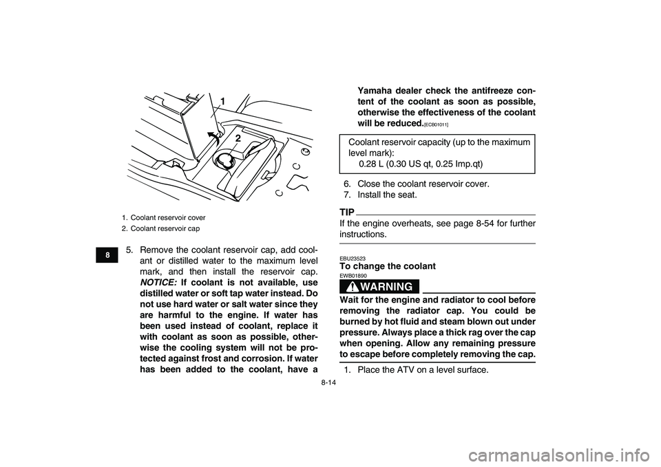
5. Remove the coolant reservoir cap, add cool-
ant or distilled water to the maximum level
mark, and then install the reservoir cap.
NOTICE:
If coolant is not available, use
distilled water or soft tap water instead. Do
not use hard water or salt water since they
are harmful to the engine. If water has
been used instead of coolant, replace it
with coolant as soon as possible, other-
wise the cooling system will not be pro-
tected against frost and corrosion. If water
has been added to the coolant, have aYamaha dealer check the antifreeze con-
tent of the coolant as soon as possible,
otherwise the effectiveness of the coolant
will be reduced.
[ECB01011]
6. Close the coolant reservoir cover.
7. Install the seat.
TIP
If the engine overheats, see page 8-54 for further
instructions.
EBU23523
To change the coolantWARNING
EWB01890
Wait for the engine and radiator to cool before
removing the radiator cap. You could be
burned by hot fluid and steam blown out under
pressure. Always place a thick rag over the cap
when opening. Allow any remaining pressure
to escape before completely removing the cap.
1. Place the ATV on a level surface.
1. Coolant reservoir cover
2. Coolant reservoir cap
1
2
Coolant reservoir capacity (up to the maximum
level mark):
0.28 L (0.30 US qt, 0.25 Imp.qt)
✦✯��✬�✩✧�✤✲✣ ✤✧ ��
����������������������
Page 93 of 146
8-15
1
2
3
4
5
6
78
9
10
11
2. Remove the radiator cover by removing the
screws.
3. Place a container under the engine and re-
move the coolant drain bolts.4. Remove the radiator cap.
1. Radiator cover
2. Screw
12
2
1. Coolant drain bolt
11
✦✯��✬�✩✧�✤✲✣ ✤� ��
����������������������
Page 94 of 146
8-16
1
2
3
4
5
6
78
9
10
11
5. Remove the coolant reservoir cap. 6. Disconnect the hose on the coolant reservoir
side and drain the coolant from the coolant
reservoir.
1. Radiator cap
1
1. Coolant reservoir cap
1
✦✯��✬�✩✧�✤✲✣ ✤✩ ��
����������������������
Page 95 of 146

8-17
1
2
3
4
5
6
78
9
10
11
7. After draining the coolant, thoroughly flush the
cooling system with clean tap water.
8. Replace the coolant drain bolt washers if they
are damaged, and then tighten the coolant
drain bolts to the specified torque.
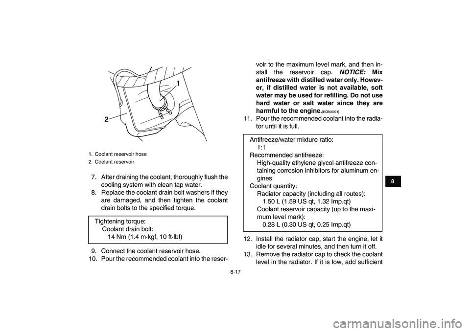
9. Connect the coolant reservoir hose.
10. Pour the recommended coolant into the reser-voir to the maximum level mark, and then in-
stall the reservoir cap.
NOTICE:
Mix
antifreeze with distilled water only. Howev-
er, if distilled water is not available, soft
water may be used for refilling. Do not use
hard water or salt water since they are
harmful to the engine.
[ECB00991]
11. Pour the recommended coolant into the radia-
tor until it is full.
12. Install the radiator cap, start the engine, let it
idle for several minutes, and then turn it off.
13. Remove the radiator cap to check the coolant
level in the radiator. If it is low, add sufficient
1. Coolant reservoir hose
2. Coolant reservoir
Tightening torque:
Coolant drain bolt:
14 Nm (1.4 m·kgf, 10 ft·lbf)
1
2
Antifreeze/water mixture ratio:
1:1
Recommended antifreeze:
High-quality ethylene glycol antifreeze con-
taining corrosion inhibitors for aluminum en-
gines
Coolant quantity:
Radiator capacity (including all routes):
1.50 L (1.59 US qt, 1.32 Imp.qt)
Coolant reservoir capacity (up to the maxi-
mum level mark):
0.28 L (0.30 US qt, 0.25 Imp.qt)
✦✯��✬�✩✧�✤✲✣ ✤✪ ��
����������������������
Page 96 of 146
8-18
1
2
3
4
5
6
78
9
10
11
coolant until it reaches the top of the radiator,
and then install the radiator cap.
14. Start the engine, and then check for coolant
leakage.
TIP
If any leakage is found, have a Yamaha dealer
check the cooling system.
15. Install the radiator cover by installing the
screws.
EBU23623
Cleaning the air filter element
The air filter element should be cleaned at the in-
tervals specified in the periodic maintenance and
lubrication chart. Clean or, if necessary, replace
the air filter element more frequently if you are
riding in unusually wet or dusty areas.
TIP
There is a check hose at the bottom of the air filter
case. If dust or water collects in this hose, empty
the hose and clean the air filter element and air fil-
ter case.1. Place the ATV on a level surface.
2. Remove the seat. (See page 4-11.)
3. Remove the air filter case cover by unhooking
the holders.
1. Air filter case check hose
1
✦✯��✬�✩✧�✤✲✣ ✤✫��
����������������������
Page 103 of 146

8-25
1
2
3
4
5
6
78
9
10
11
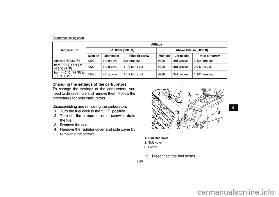
Carburetor setting chart
Changing the settings of the carburetors
To change the settings of the carburetors, you
need to disassemble and remove them. Follow the
procedures for both carburetors.
Disassembling and removing the carburetors
1. Turn the fuel cock to the “OFF” position.
2. Turn out the carburetor drain screw to drain
the fuel.
3. Remove the seat.
4. Remove the radiator cover and side cover by
removing the screws.
5. Disconnect the fuel hoses.
TemperatureAltitude
0
–1500 m (5000 ft) Above 1500 m (5000 ft)
Main jet Jet needle Pilot air screw Main jet Jet needle Pilot air screw
Above 0 °C (32 °F) #200 3rd groove 2.0 turns out #190 3rd groove 2 1/2 turns out
from +5 °C (41 °F) to
–15 °C (5 °F)#220 3rd groove 1 1/2 turns out #200 3rd groove 2.0 turns out
from –10 °C (14 °F) to
–30 °C (–22 °F)#240 4th groove 1 1/2 turns out #220 3rd groove 1 1/2 turns out
1. Radiator cover
2. Side cover
3. Screw
1
2 3 3
3
3
✦✯��✬�✩✧�✤✲✣ ✥� ��
����������������������
Page 109 of 146

8-31
1
2
3
4
5
6
78
9
10
11
5. Move the throttle lever a few times and re-
check the position.
6. Install the fuel tank, side cover, radiator cover
and air filter case cover.
7. Connect the fuel hoses.
8. Install the seat.
EBU24020
Adjusting the engine idling speed
The engine idling speed must be checked and, if
necessary, adjusted as follows at the intervals
specified in the periodic maintenance and lubrica-tion chart.TIP
�
A diagnostic tachometer is needed to make this
adjustment.
�
The carburetor synchronization and the throttle
cable free play must be checked, and adjusted if
necessary, before adjusting the engine idling
speed.
1. Start the engine and warm it up.
TIP
The engine is warm when it quickly responds to the
throttle.
2. Attach the tachometer to the spark plug lead.
3. Turn in both pilot air screws until they lightly
seat.
4. Turn out both pilot air screws to specification.
(See the “Changing the carburetor settings”
section on the page 8-23.)
1. Adjusting nut
2. Locknut
1
2
✦✯��✬�✩✧�✤✲✣ ✦✤ ��
����������������������