2010 VOLKSWAGEN TRANSPORTER ESP
[x] Cancel search: ESPPage 291 of 486
Vehicles with ParkPilot at the front and rear
Segment colour if an
Area of the vehicle Distance of the vehicle Acoustic sig-obstacle has been de-from an obstacle nal tected (colour display only)
® Rear centre approx. 31 -160 cm
Rear side approx. 31 -60 cm Intermittent Yellow
® Front centre approx. 31 -120 cm tone
Front side approx. 31 -60 cm
@and@ Obstacle close approx. 0 -30 cm Constant tone Red to the vehicle8)
•) The distance range for the constant lone to the rear of the vehicle is slightly larger for vehicles w1th a factory-filled towing bracket.
When towing a trailer
In vehicles with a factory-fitted towing bracket and a trailer connected via the vehicle electrics, a cor-responding display appears on the screen of the factory-fitted radio or navigation system, depend-ing on the vehicle equipment level. The distance behind the vehicle will then no longer be shown.
Muting the ParkPilot signal tones
The acoustic signals for the ParkPilot can be mut-ed by touching the @function button on the screen (in colour display only). Touch the function button again to switch the acoustic signals back on.
Reversing camera (Rear Assist)
o:n Introduction
This chapter contains information on the following subjects:
General information ..................... . Camera.
292 293
Operating the rear view camera system . . . . . 294
....................... 2%
The reversing camera (Rear Assist)
makes it easier for the driver to see be-
hind the vehicle when parking or revers-
ing.
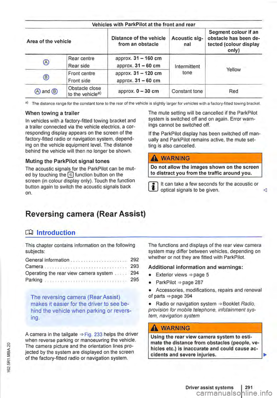
A camera in the tailgate 233 helps the driver when reverse parking or manoeuvring the vehicle. The camera picture and the orientation lines pro-jected by the system are displayed on the screen of the factory-fitted radio or navigation system.
The mute setting will be cancelled if the ParkPilot system is switched off and on again. Error warn-ings cannot be switched off.
If the ParkPilot display has been switched off man-ually and ParkPilot remains active, the mute set-ting is also cancelled.
A WARNING
Do not allow the Images shown on the screen to distract you from the traffic around you.
m it can take a few seconds for the acoustic or W optical signals to be given.
Additional information and warnings:
• Exterior views =>page 5
• ParkPilot 287
• Accessories, modifications, repairs and renewal of parts 394
• Radio or navigation system Radio, provision for mobile telephone, infotainment sys-tem, navigation system
A WARNING
Using the rear view camera system to esti-mate the distance from obstacles (people, ve-hicles etc.) Is Inaccurate and could cause ac-cidents and severe injuries. 11>
Driver assist systems I 291
Page 304 of 486
When the highest level is reached, the distance re-turns to the lowest level when the button is press-ed again.
The distance level can also be set using the Q or Q buttons on the multifunction steering wheel im-mediately after the(!) button on the multifunction steering Fig. 241 has been pressed.
Select the Settings menu, Assist systems submenu, ACC to set the distance to be used when the ACC is switched on 24.
Setting the gearbox programme
The acceleration response can be influenced by the gearbox programme selected. The programme can be set Using the ACC option in the Assistant submenu in the Settings menu. The following gearbox programmes can be selected:
• Normal
• Sport
• Eco
The following conditions can prevent the adaptive cruise control (ACC) from reacting:
• If the accelerator is depressed.
• If no gear is selected.
• If the ESC is taking corrective action.
• If there is a fault in several brake lights on the vehicle or on a trailer with an electrical connection to the vehicle.
• If the vehicle is reversing.
• System version 1: if the vehicle is travelling faster than approximately 160 km/h (1 00 m ph).
• System version 2: if the vehicle is travelling faster than approximately 210 km/h (130 mph).
A WARNING
If you do not maintain the minimum distance to a vehicle In front and the difference In speed between the two vehicles is so great that the braking action of the adaptive cruise control (ACC) is insufficient, you are In dan-ger of colliding with the vehicle in front. You should reduce the vehicle speed immediately with the foot brake.
• The adaptive cruise control (ACC) may not be able to detect all driving situations cor-rectly.
• Leaving your foot on the accelerator means that the adaptive cruise control (ACC) will not brake automatically. This is because manual acceleration overrides the system.
• You should always be prepared to brake the vehicle yourself.
• Observe country-specific regulations re-garding the minimum distance.
m The set speed will be deleted if the ignition or L!.J the adaptive cruise control (ACC) is switched off.
m The adaptive cruise control (ACC) is auto-L!.J matically deactivated when the traction con-trol system (TCS) is deactivated.
m In vehicles with a start/stop system, the en-L!.J gine is switched off automatically during the stationary phase of adaptive cruise control (ACC) and is then restarted for moving off.
situations
1""111 First read and observe the introductory L-J,:.IJ Information and safety warnings & on page 298.
The adaptive cruise control (ACC) should be switched off in the following situations due to sys-tem limitations &:
304 I While driving
• When turning off roads, driving around round-abouts, narrow curves, joining motorways, exiting from motorways or driving through road works, to prevent the vehicle from unnecessarily accelerat-ing to the set speed in these situations
• When driving through a tunnel as this situation could impair the system function.
• On roads with more than one lane, if other vehi-cles are driving more slowly in the fast lane. The slower vehicles In the other lane would be overtak-en from the right side in this case.
• In heavy rain, snow or spray as vehicles travel-ling ahead cannot be monitored sufficiently or maybe cannot be monitored at all. .,.
Page 306 of 486
Acceleration can be stopped at any time by de-pressing the brake pedal or pressing the(@ or @ button on the multifunction steering wheel 302.
When driving through bends
While driving through bends, the radar sensor may sometimes lose the vehicle travelling ahead or may react to a vehicle in the next lane 242 !Al. In such situations, the vehicle might decelerate unnecessarily or not react to the vehicle in front. In this case the driver must override the adaptive cruise control (ACC) by depressing the accelerator, or interrupt the braking procedure by depressing the brake pedal or pressing or @ button on the multifunction steering wheel 302.
Driving in tunnels
The radar sensor function may be restricted in tun-nels. Switch off the adaptive cruise control (ACC) in tunnels.
Narrow vehicles and a zig-zag traffic situation
Narrow vehicles and vehicles travelling slightly to the left or right of your vehicle will only be recog-nised by the radar sensor once they have entered the radar range 242@ This applies in par-ticular to narrow vehicles such as motorbikes. If re-quired, brake the vehicle yourself.
Vehicles with special load or special equipment
Any load or accessories on other vehicles that pro-trude from the side, rear or over the roof of the ve-hicle may not be detected by the adaptive cruise control (ACC) .
Switch off the adaptive cruise control (ACC) when the vehicle ahead has special load or special equipment, or while overtaking vehicles of this kind. If required. brake the vehicle yourself.
When other vehicles change lanes
Vehicles that are very close when they move into your lane can only be detected by the radar sen-sors when they have moved into the sensor range. This means that the adaptive cruise control (ACC) may have a delayed reaction =>Fig. 243@]. If re-quired, brake the vehicle yourself.
Stationary vehicles
The adaptive cruise control (ACC) does not detect stationary objects during a journey, e.g. stationary traffic or a vehicle that has broken down.
306 I While driving
If a stationary vehicle is hidden behind a vehicle that has been detected by the adaptive cruise con-trol (ACC) and this vehicle turns off the road or changes lane, the adaptive cruise control (ACC) will not be able to react to the stationary vehicle 243 [Q]. If required, brake the vehicle your-self.
Oncoming vehicles and vehicles crossing your path
The adaptive cruise control (ACC) does not react to approaching vehicles or vehicles crossing your path.
Metal objects
Metal objects, such as tracks in the road or metal plates used in roadworks, can confuse the radar sensor and cause incorrect reactions from the adaptive cruise control (ACC) .
Possible radar sensor function impairments
The adaptive cruise control (ACC) will switch off temporarily if the radar sensor function is impaired, e.g. due to heavy rain, spray, snow, ice or mud. A corresponding message will appear on the instru-ment cluster display. Clean the radar sensors as required.
The adaptive cruise control (ACC) will automatical-ly be available again as soon as the radar sensors are no longer impaired. The message on the in-strument cluster display goes out, and the adaptive cruise control (ACC) can be reactivated.
Strong reflected radiation of the radar signal, e.g. in multi-storey car parks, can impair the function of the radar sensor.
Towing a trailer
The adaptive cruise control (ACC) operates with reduced dynamics when the vehicle is towing a trailer.
Overheated brakes
If the brakes overheat, e.g. following heavy braking or when driving down steep inclines for long peri-ods, the adaptive cruise control (ACC) may be de-activated temporarily. A corresponding message will appear on the instrument cluster display. lt is then not possible to activate the adaptive cruise control (ACC).
As soon as the temperature of the brakes has de-creased sufficiently, the adaptive cruise control (ACC) can be activated again. The message on the instrument cluster display goes out. If the mes-sage ACC not ava i 1 able does not go out for a long time, there is a fault. Go to a qualified work-shop. Volkswagen recommends using a Volkswa-gen dealership for this purpose.
Page 307 of 486
Area monitoring system (Front Assist)
COJ Introduction
This chapter contains information on the following subjects:
Displays . . . . . . . . . 308
Radar sensor . . 309
Front scan system (Front Assist) 309 Temporarily switch off the front scan system (Front Assist) in the following situations 310
City Emergency Brake function 311
System limits . . . . . . . . . . . . . . . . 312
The area monitoring system (Front As-
sist) can help to avoid rear-end colli-
sions.
Within the limits of the system, Front Assist can warn the driver about imminent collisions, prepare the vehicle for emergency braking in case of dan-ger, assist with braking, and initiate automatic braking.
Front Assist is not a substitute for the full con-centration of the driver.
Additional information and warnings:
• Exterior views 5
• Volkswagen information system 24
• Cruise control system (CCS) 295
• Adaptive cruise control (ACC) 298
• Accessories, modifications, repairs and renewal of parts 394
Distance warning
If the system detects danger from driving too close to the vehicle in front, within the speed range of approx. 60 km/h (37 mph) up to 210 km/h (130 mph), the system warns the driver by showing a corresponding message on the instrument clus-ter display 244 [ID.
The warning period varies according to the traffic situation and the driver's response.
Advance warning
If the system detects a danger of collision with the vehicle ahead, within the speed range of approx. 30 km/h (18 m ph) up to 210 km/h (130 mph), the system warns the driver by emitting a signal tone and showing a corresponding message on the in-strument cluster display 245.
The warning period varies according to the traffic situation and the driver's response. At the same time it prepares the vehicle for possible emergency
Urgent warning
If the driver fails to respond to the advance warn-ing, within a speed range of approx. 30 km/h (18 mph) to 210 km/h (130 mph), the system can initiate a quick jolt of the brake in order to draw the driver's attention to the increasing danger of a colli-sion. The warning period varies according to the traffic situation and the driver's response.
Automatic braking
If the driver does not react to the acute warning, within a speed range of approx. 4 km/h (2.5 mph) to 210 km/h (130 mph), the vehicle can brake auto-matically using brake pressure with gradually in-creasing intensity. By reducing speed during a pos-sible collision the system can help to minimise the consequences of an accident.
Brake assistance
If the system detects that the driver is not braking sufficiently when there is a risk of collision, the sys-tem can increase the braking force and thereby help to prevent a collision from speeds of approxi-mately 4 km/h (2.5 mph) to 210 km/h (130 mph). Brake assistance works only for as long as the brake pedal is pressed hard.
A WARNING
The Intelligent technology used in Front As-sist cannot overcome the laws of physics, and functions only within the limits of the system. The driver Is always responsible for braking in time. If Front Assist issues a warn-ing, immediately apply the foot brake to slow the vehicle down or avoid the obstacle, de-pending on the traffic situation.
• Adapt your speed and distance from the vehicles ahead to suit visibility, weather, road and traffic conditions.
• Front Assist cannot prevent accidents and serious injuries on Its own.
• Front Assist can issue unnecessary warn-Ings and carry out unwanted braking inter-ventions in certain complex driving situa-tions, e.g. at traffic Islands.
Driver assist systems 307
Page 312 of 486
System limits
r-('n First read and observe the Introductory L-J,:.U Information and safety warnings & on page 307.
The area monitoring system (Front Assist) has physical and system-related limits. The driver may therefore feel that, in certain circumstances, some Front Assist reactions occur unexpectedly or with a delay. You should therefore always be prepared to take full control of the vehicle if necessary.
The following conditions can prevent Front Assist from reacting, or cause a delay in its reaction:
• In tight bends.
• If the accelerator is fully depressed.
• If Front Assist is switched off or there is a fault.
• If TCS or ESC is switched off manually.
• If the ESC is taking corrective action.
• If there is a fault in several brake lights on the vehicle or on a trailer with an electrical connection to the vehicle.
• If the radar sensor is dirty or covered.
• If the vehicle is reversing.
• Under hard acceleration.
• In snow or heavy rain.
• In case of narrow vehicles, e.g. motorbikes.
• If vehicles are travelling slightly to the left or right of your vehicle.
• If vehicles are crossing in front of your vehicle.
• If there is oncoming traffic.
• In uncertain traffic situations.
• 1/Vhen loads or attachment parts on other vehi-cles protrude to the side, rear or above the normal dimensions of the vehicle.
COJ Introduction
This chapter contains information on the following subjects:
Indicator lamp ... .
Operation ....... .
Driving situations ..........•.............
313
314
315
The lane change assist system (Side As-
sist) provides assistance when checking
for traffic behind the vehicle.
The lane change assist system cannot be switched on if the factory-fitted towing bracket is electrically connected to the trailer. The lane change assist system must be switched off manually for non-fac-tory-fitted towing brackets.
The lane change assist system has been designed for use on surfaced roads only.
Additional information and warnings:
• Exterior views =<>page 5
• Volkswagen information system =<>page 24
• Accessories, modifications, repairs and renewal of parts =<>page 394.
3121 While drivmg
A WARNING
The Intelligent technology of the lane change assist system (Side Assist) cannot change the laws of physics or the system-related ve-hicle limitations. Always take care when us-Ing the lane change assist system as you could otherwise cause accidents or Injuries. The system Is not a substitute for the full concentration of the driver.
• Adapt your speed and distance from the vehicles ahead to suit visibility, weather, road and traffic conditions.
• Your hands should always be on the steer-Ing wheel so that you can steer at any time.
• Pay attention to the visual displays in the exterior mirror housing and in the Instrument cluster display, and respond to the com-mands.
• The lane change assist system may react to special roadside structures, e.g. high or offset crash barriers. This can lead to error warnings. ,..
Page 314 of 486
Operation
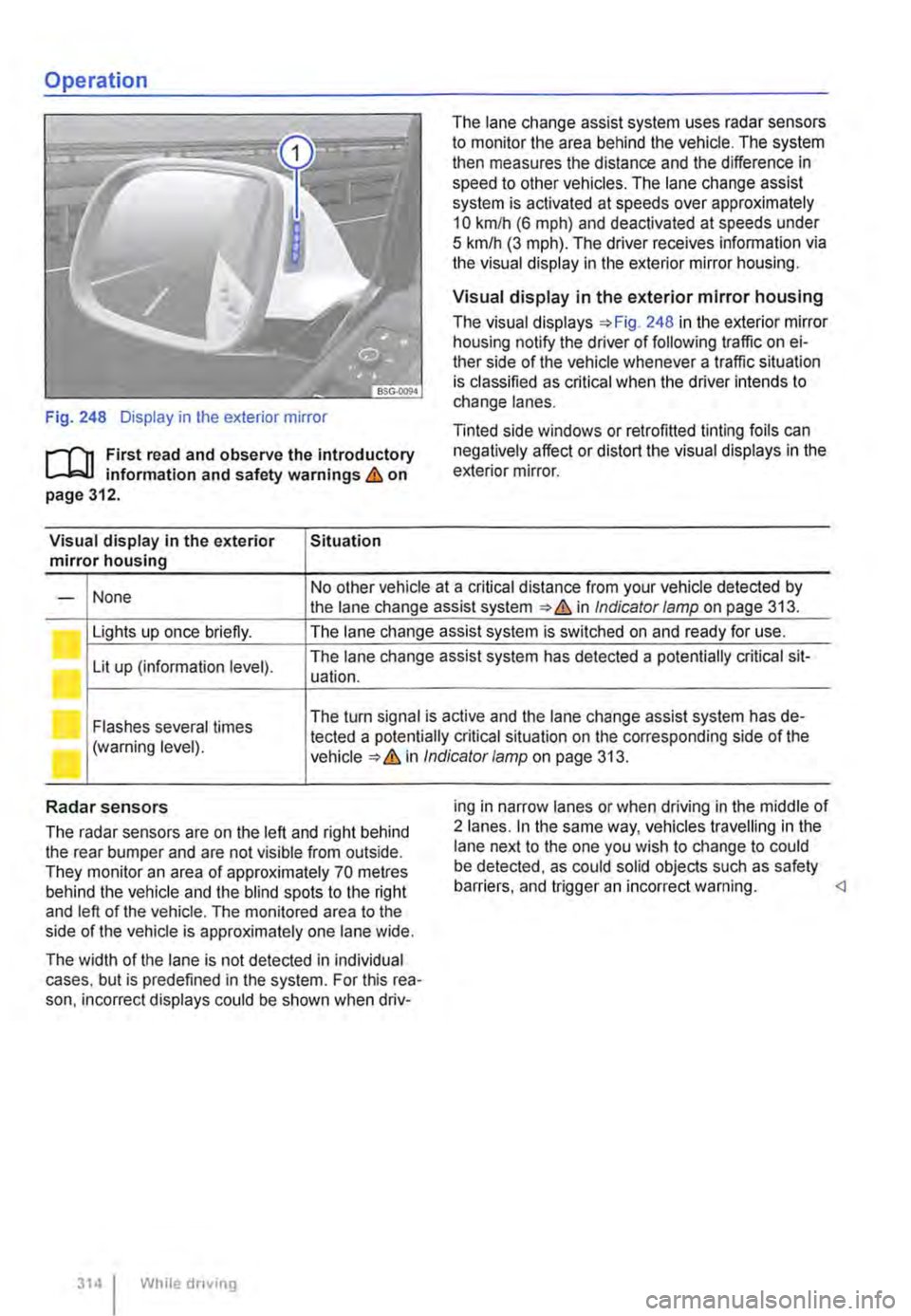
Fig. 248 Display in the exterior mirror
r-f"n First read and observe the introductory L-W! information and safety warnings & on page 312.
Visual display in the exterior Situation mirror housing
The lane change assist system uses radar sensors to monitor the area behind the vehicle. The system then measures the distance and the difference in speed to other vehicles. The lane change assist system is activated at speeds over approximately 10 km/h (6 m ph) and deactivated at speeds under 5 km/h (3 mph). The driver receives infonmation via the visual display in the exterior mirror housing.
Visual display in the exterior mirror housing
The visual displays 248 in the exterior mirror housing notify the driver of following traffic on ei-ther side of the vehicle whenever a traffic situation is classified as critical when the driver intends to change lanes.
Tinted side windows or retrofitted tinting foils can negatively affect or distort the visual displays in the exterior mirror.
None No other vehicle at a critical distance from your vehicle detected by -the lane change assist system & in Indicator lamp on page 313.
Lights up once briefly. The lane change assist system is switched on and ready for use.
Lit up (information level). The lane change assist system has detected a potentially critical sit-uation.
Flashes several times The turn signal is active and the lane change assist system has de-
(warning level). tected a potentially critical situation on the corresponding side of the in Indicator/amp on page 313.
Radar sensors
The radar sensors are on the left and right behind the rear bumper and are not visible from outside. They monitor an area of approximately 70 metres behind the vehicle and the blind spots to the right and left of the vehicle. The monitored area to the side of the vehicle is approximately one lane wide.
The width of the lane is not detected in individual cases. but is predefined in the system. For this rea-son. incorrect displays could be shown when driv-
314 I While driving
ing in narrow lanes or when driving in the middle of 2 lanes. In the same way, vehicles travelling in the lane next to the one you wish to change to could be detected, as could solid objects such as safety barriers. and trigger an incorrect warning.
Page 316 of 486
Additional information and warnings:
• Volkswagen information system =>page 24
• Accessories, modifications, repairs and renewal of parts (information stored in the control units) =>page 394
A WARNING
The Intelligent technology used In the Driver Alert System cannot overcome the laws of physics, and functions only within the limits of the system. Do not let the extra conven-ience afforded by the Driver Alert System tempt you Into taking any risks when driving -this can cause accidents. During a long trip, plan regular and sufficient breaks.
• The driver Is responsible at all times for their fitness to drive.
• Never drive a vehicle when you are tired.
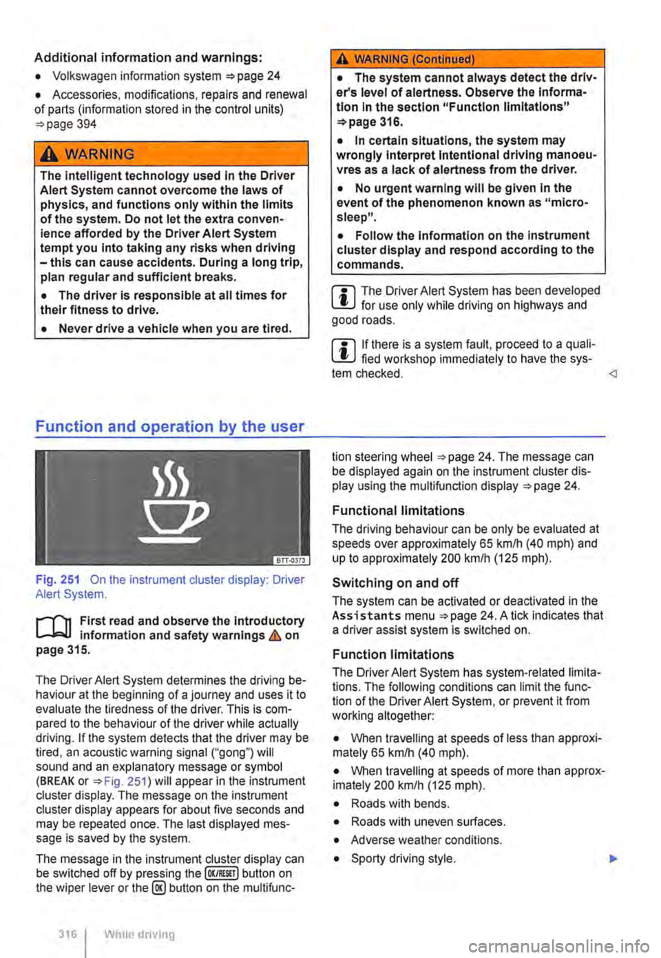
Fig. 251 On the instrument cluster display: Driver Alert System.
r--('n First read and observe the Introductory Information and safety warnings&. on page 315.
The Driver Alert System determines the driving be-haviour at the beginning of a journey and uses it to evaluate the tiredness of the driver. This is com-pared to the behaviour of the driver while actually driving. If the system detects that the driver may be tired, an acoustic warning signal ("gong") will sound and an explanatory message or symbol (BREAK or =>Fig. 251) will appear in the instrument cluster display. The message on the instrument cluster display appears for about five seconds and may be repeated once. The last displayed mes-sage is saved by the system.
The message in the instrument cluster display can be switched off by pressing the (OK/RESIT I button on the wiper lever or the@ button on the multifunc-
316 I Whole driving
A WARNING (Continued)
• The system cannot always detect the driv-er's level of alertness. Observe the Informa-tion In the section "Function limitations" =>page 316.
• In certain situations, the system may wrongly Interpret Intentional driving manoeu-vres as a lack of alertness from the driver.
• No urgent warning will be given In the event of the phenomenon known as "micro-sleep".
• Follow the Information on the Instrument cluster display and respond according to the commands.
m The Driver Alert System has been developed l!..J for use only while driving on highways and good roads.
m If there is a system fault, proceed to a quali-L!..J fied workshop immediately to have the sys-tem checked.
Functional limitations
The driving behaviour can be only be evaluated at speeds over approximately 65 kmlh (40 mph) and up to approximately 200 km/h (125 m ph).
Switching on and off
The system can be activated or deactivated in the Assistants menu =>page 24. A tick indicates that a driver assist system is switched on.
Function limitations
The Driver Alert System has system-related limita-tions. The following conditions can limit the func-tion of the Driver Alert System, or prevent it from working altogether:
• When travelling at speeds of less than approxi-mately 65 km/h (40 mph).
• When travelling at speeds of more than approx-imately 200 km/h (125 mph).
• Roads with bends.
• Roads with uneven surfaces.
• Adverse weather conditions.
• Sporty driving style. .,..
Page 318 of 486
Function and operation
•
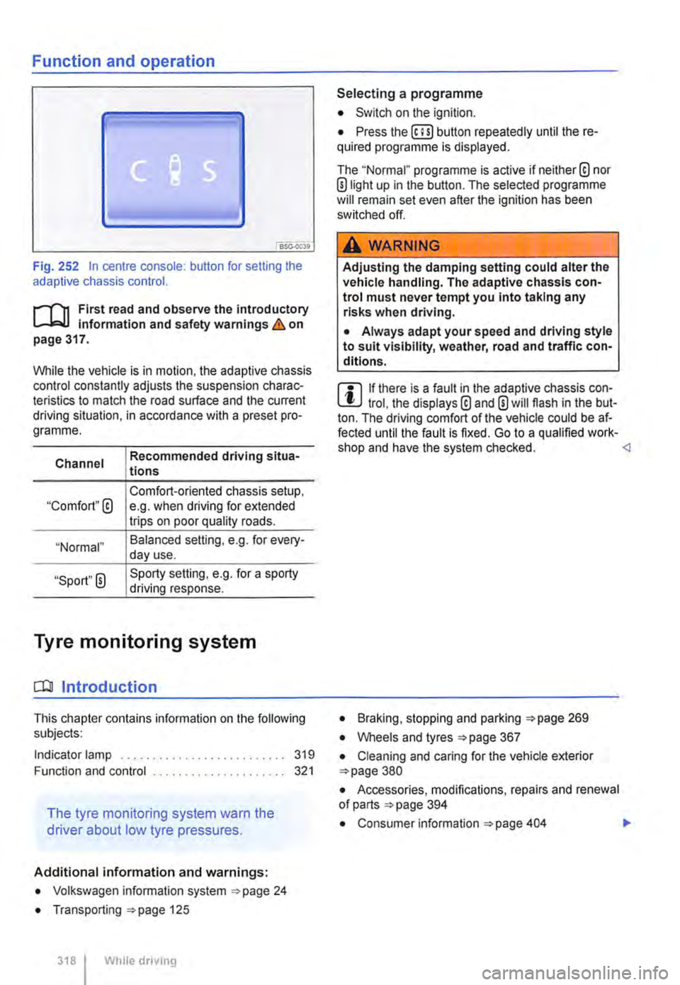
Fig. 252 In centre console: button for setting the adaptive chassis control.
r-f"n First read and observe the introductory Information and safety warnings & on page 317.
While the vehicle is in motion, the adaptive chassis control constantly adjusts the suspension charac-teristics to match the road surface and the current driving situation, in accordance with a preset pro-gramme.
Channel
"Comfort"@
"Normal"
"Sport" 0
Recommended driving situa-tions
Comfort-oriented chassis setup, e.g. when driving for extended trips on poor quality roads.
Balanced selling, e.g. for every-day use.
Sporty setting, e.g. for a sporty driving response.
Tyre monitoring system
CO! Introduction
This chapter contains information on the following subjects:
Indicator lamp .......................... 319
Function and control ..................... 321
The tyre monitoring system warn the
driver about low tyre pressures.
Additional information and warnings:
• Volkswagen information system ""page 24
• Transporting ""page 125
318 I While dnvmg
Selecting a programme
• Switch on the ignition.
• Press the (ili) button repeatedly until the re-quired programme Is displayed.
The "Normal" programme is active if neither® nor ®light up in the button. The selected programme will remain set even after the ignition has been switched off.
A WARNING
Adjusting the damping setting could alter the vehicle handling. The adaptive chassis con-trol must never tempt you into taking any risks when driving.
• Always adapt your speed and driving style to suit visibility, weather, road and traffic con-ditions.
m If there is a fault in the adaptive chassis con-l!:J trol, the displays® and 0 will flash in the but-ton. The driving comfort of the vehicle could be af-fected until the fault is fixed. Go to a qualified work-shop and have the system checked. <1
• Braking, stopping and parking :;.page 269
• Wheels and tyres =page 367
• Cleaning and caring for the vehicle exterior =page 380
• Accessories, modifications, repairs and renewal of parts =page 394
• Consumer information =page 404 .,.