2010 VOLKSWAGEN TRANSPORTER ECU
[x] Cancel search: ECUPage 157 of 486
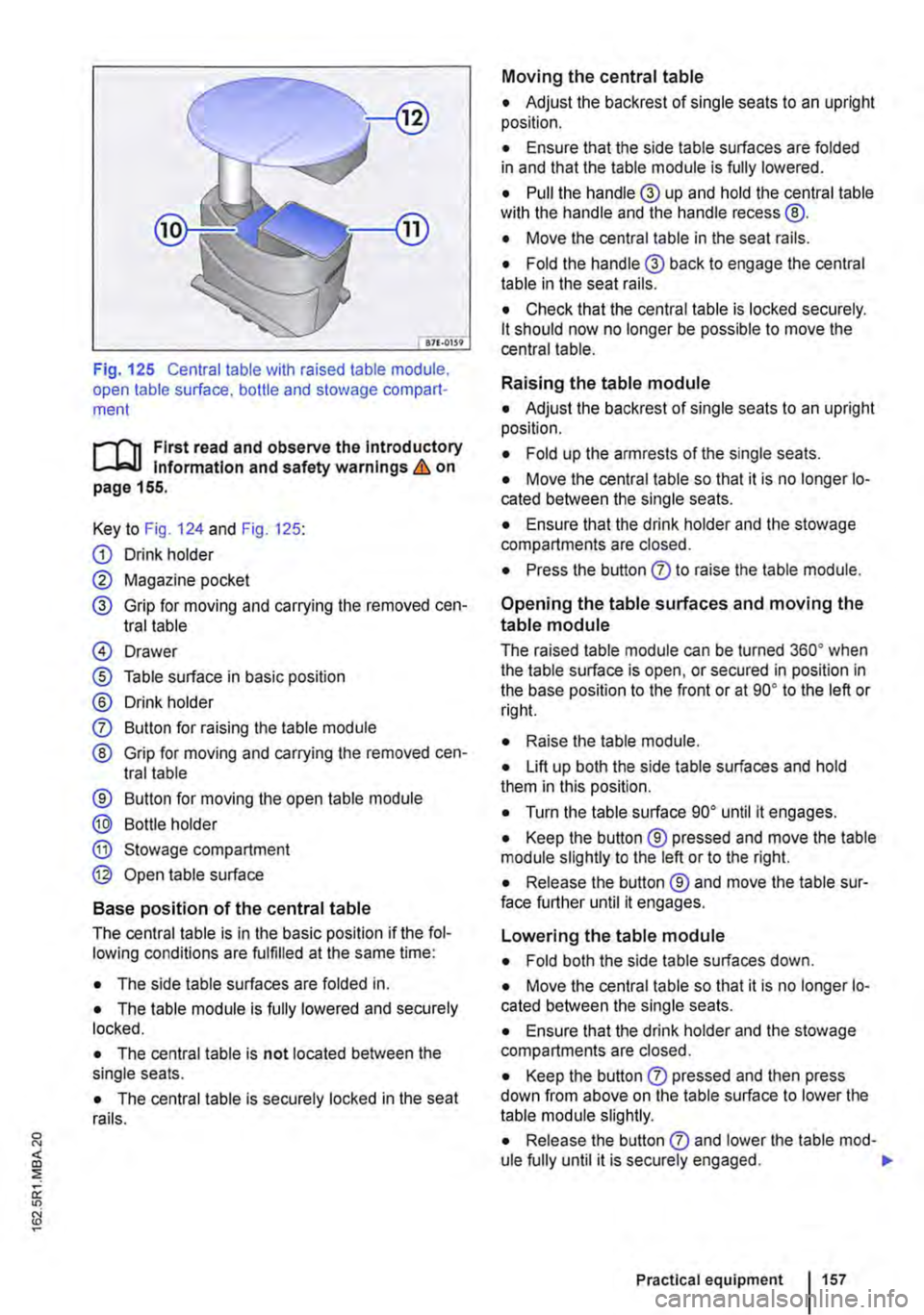
Fig. 125 Central table with raised table module, open table surface. bottle and stowage compart-ment
r-1'11 First read and observe the Introductory l.-Jr:-lJ Information and safety warnings & on page 155.
Key to Fig. 124 and Fig. 125:
G) Drink holder
0 Magazine pocket
® Grip for moving and carrying the removed cen-tral table
@ Drawer
® Table surface in basic position
® Drink holder
0 Button for raising the table module
® Grip for moving and carrying the removed cen-tral table
® Button for moving the open table module
® Bottle holder
® Stowage compartment
@ Open table surface
Base position of the central table
The central table is in the basic position if the fol-lowing conditions are fulfilled at the same time:
• The side table surfaces are folded in.
• The table module is fully lowered and securely locked.
• The central table is not located between the single seats.
• The central table is securely locked in the seat rails.
Moving the central table
• Adjust the backrest of single seats to an upright position.
• Ensure that the side table surfaces are folded in and that the table module is fully lowered.
• Pull the handle® up and hold the central table wilh the handle and the handle recess @.
• Move the central table in the seat rails.
• Fold the handle® back to engage the central table in the seat rails.
• Check that the central table is locked securely. lt should now no longer be possible to move the central table.
Raising the table module
• Adjust the backrest of single seats to an upright position.
• Fold up the armrests of the single seats.
• Move the central table so that it is no longer lo-cated between the single seats.
• Ensure that the drink holder and the stowage compartments are closed.
• Press the button 0 to raise the table module.
Opening the table surfaces and moving the
table module
The raised table module can be turned 36o• when the table surface is open, or secured in position in the base position to the front or at go• to the left or rig hi.
• Raise lhe table module.
• Lift up both the side table surfaces and hold them in this position.
• Turn the table surface go• until it engages.
• Keep the button ® pressed and move the table module slightly to the left or to the right.
• Release the button ® and move the table sur-face further until it engages.
Lowering the table module
• Fold both the side table surfaces down.
• Move the central table so that it is no longer lo-cated between the single seats.
• Ensure that the drink holder and the stowage compartments are closed.
• Keep the button 0 pressed and then press down from above on the table surface to lower the table module slightly.
• Release the button 0 and lower lhe table mod-ule fully until it is securely engaged. .,.
Practical equipment 1157
Page 158 of 486
Removing the central table
The central table can be removed more easily by two people than by one person.
• Remove front protective covers from the central seat rails.
• Turn the single seats so that they face the di-rection of travel.
• Adjust the back rest of single seats to an upright position.
• Fold up the armrests of the single seats.
• Pull the handle @ up and hold the central table with the handle and the handle recess@.
• Push the central table forwards to the point where it can be lifted out of the slots in the seat rails.
• Lift the central table out.
• Put down the central table carefully so that the rollers and feet are not soiled or damaged.
• Place the removed covers on the open slots in the seat rails.
Fitting the central table
The central table can be installed more easily by two people than by one person.
• Remove front protective covers from the central seat rails.
• Turn the single seats so that they face the di-rection of travel.
Cool box
c:cn Introduction
This chapter contains information on the following subjects:
Fitting and removing the cool box
Switching the cool box on and off 159 161
The cool box may be used while the vehicle is in motion only if it is fitted to the adapter plate.
Power for the cool box can be supplied by any of the 12-volt sockets in the vehicle. The power con-sumption is approx. 33 watts. The cool box has a capacity of 32 litres.
Follow instructions provided for the installation and use of the cool box and keep it in the vehicle wal-let.
As far as possible, keep food and drinks in the cool box in leak-proof containers. Do not overfill the cool box such that air circulation is impaired.
158 Before the journey
• Adjust the backrest of single seats to an upright position.
• Fold up the armrests of the single seats.
• Pull the handle @ up and hold the central table with the handle and the handle recess®.
• Insert the central table guides into the recesses in the seat rails.
• Insert the central table into the seat rails and push them back, so that the removed covers can be placed on the open slots in the seat rails.
• Fold the handle@ back to engage the central table in the seat rails.
• Check that the central table is locked securely. it should now no longer be possible to move the central table.
• Do not raise the table module when the cen-tral table Is located between the single seats. This could cause damage to the table.
The vehicle battery will be drained if the cool box is used when the engine is switched off. For this rea-son, the cool box is fitted with a battery monitor. The battery monitor will switch the cool box off if the vehicle battery has a low charge level. The bat-tery monitor will switch the cool box on again as soon as the battery has reached a suitable charge level, for example, after a long journey.
Additional information and warnings:
• Seat functions, front =>page 69
• Seat functions, rear =>page 72
• Seat functions, rear, Business =>page 182
• Seat functions, rear, California =>page 193
• Electrical sockets =>page 163
• Battery =>page 350
Page 159 of 486
• Cleaning and caring for the interior =:>page 380
• Accessories. modifications, repairs and renewal of parts =:>page 380
A WARNING
Objects that are not secured, or are secured Incorrectly, can cause serious Injuries In the event of a sudden driving or braking manoeu-vre or accident
• The cool box may be transported only if it Is fitted to the adapter plate.
• Make sure that the adapter plate is proper-ly fitted In the seat rails.
• The cool box lid must always be closed and latched when the vehicle Is In motion.
• Never use the cool box as a table or stow-age compartment when the vehicle Is In mo-tlon.
A WARNING
If the ambient temperature In the vehicle is too low, the temperature in the cool box could fall below +2•c (+35°F) degrees. This could cause the contents of the cool box to freeze and bottles and other containers to burst, potentially causing injuries.
• Do not use the cool box when the ambient temperature is too low.
CD
This could damage the cool box if the bed ex-tension is fitted (multi-flex board).
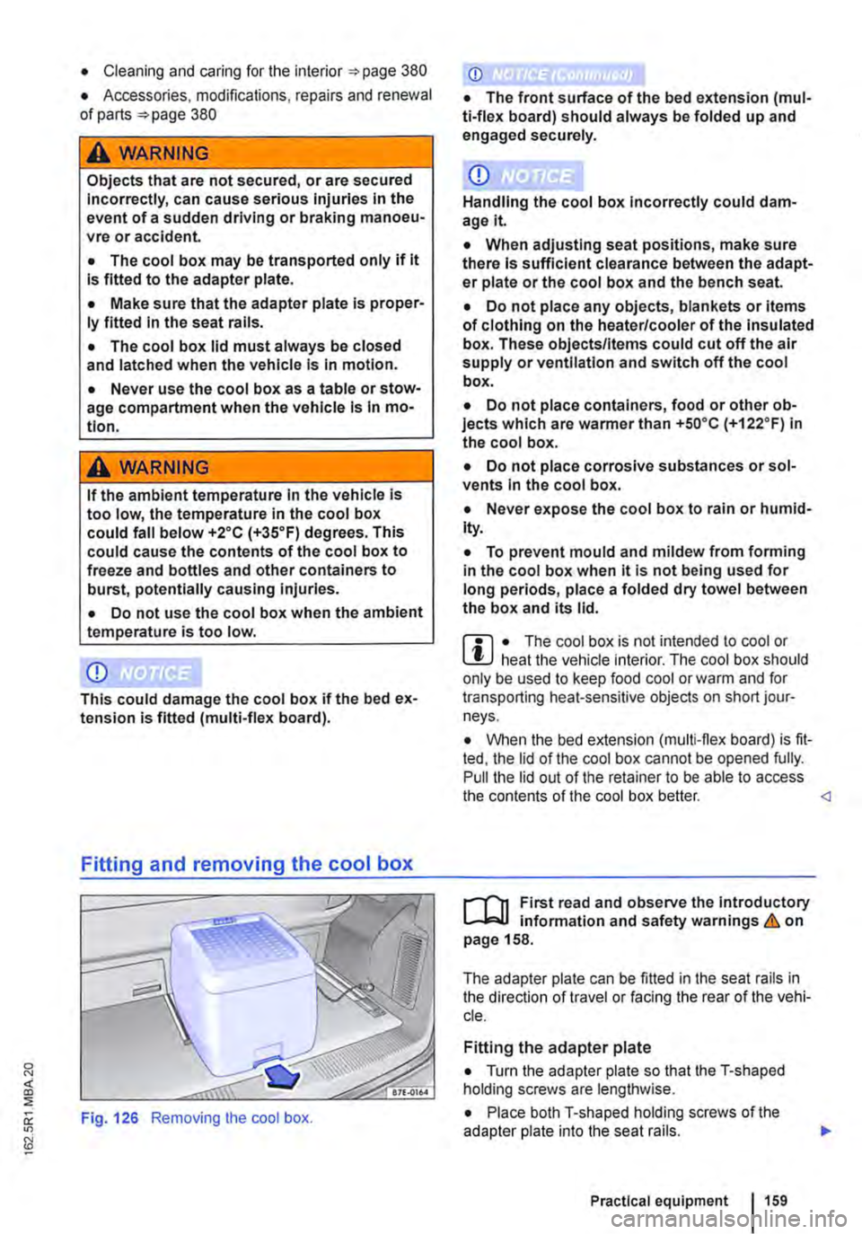
Fitting and removing the cool box
Fig. 126 Removing the cool box.
CD
• The front surface of the bed extension (mul-ti-flex board) should always be folded up and engaged securely.
CD
Handling the cool box Incorrectly could dam-age it
• When adjusting seat positions, make sure there Is sufficient clearance between the adapt-er plate or the cool box and the bench seat.
• Do not place any objects, blankets or items of clothing on the heater/cooler of the Insulated box. These objects/Items could cut off the air supply or ventilation and switch off the cool box.
• Do not place containers, food or other ob-jects which are warmer than +so•c (+122.F) in the cool box.
• Do not place corrosive substances or sol-vents In the cool box.
• Never expose the cool box to rain or humid-Ity.
• To prevent mould and mildew from forming in the cool box when it is not being used for long periods, place a folded dry towel between the box and its lid.
m • The cool box is not intended to cool or L!J heat the vehicle interior. The cool box should only be used to keep food cool or warm and for transporting heat-sensitive objects on short jour-neys.
• When the bed extension (multi-flex board) is fit-ted, the lid of the cool box cannot be opened fully. Pull the lid out of the retainer to be able to access the contents of the cool box better.
,...--("n First read and observe the Introductory L--J,:.U information and safety warnings & on page 158.
The adapter plate can be fitted in the seat rails in the direction of travel or facing the rear of the vehi-cle.
Fitting the adapter plate
• Turn the adapter plate so that the T-shaped holding screws are lengthwise.
• Place both T-shaped holding screws of the adapter plate into the seat rails.
Practical equipment 1159
Page 160 of 486
• Push both handles down.
• Turn both handles through go• so that the T-shaped holding screws are across the seat rails
• Tighten both the thumb wheels firmly.
• When fitting the adapter plate ensure sufficient clearance between the adapter plate or the cool box and the bench seat
Fitting the cool box
• Fit the adapter plate.
• Pull out the handle on the adapter plate.
• Place the cool box on the adapter plate.
• Make sure that all holding screws on the cool box are fully engaged in the corresponding holes on the adapter plate &..
• Pull the handle on the adapter plate right out.
• When fitting the cool box ensure sufficient clearance between the adapter plate or the cool box and the bench seat
Removing the cool box
• Pull out the handle on the adapter plate in the direction of the arrow 126 to unlock the cool box.
• Lift up the cool box to remove it.
• Pull the handle on the adapter plate right out.
Removing the adapter plate
• Remove the cool box.
• Turn the adapter plate so that the T-shaped holding screws are lengthwise.
• Lift up the adapter plate to remove it.
A WARNING
Objects that are not secured, or are secured incorrectly, can cause serious Injuries in the event of a sudden driving or braking manoeu-vre or accident.
160 I Before the journey
A WARNING (Continued)
• Make sure that the T-shaped holding screws In the seat rails are at right-angles (90°) to the adapter plate and correctly engag-ed.
• The T-shaped holding screws should nev-er be Inserted In the seat rails near the re-movable covers.
• Make sure that the cool box Is properly fit-ted In on the adapter plate.
CD
Handling the cool box Incorrectly could dam-agelt.
• When adjusting seat positions, make sure there Is sufficient clearance between the adapt-er plate or the cool box and the bench seat.
• Do not place any objects, blankets or Items of clothing on the heater/cooler of the Insulated box. These objects/Items could cut off the air supply or ventilation and switch off the cool box.
• Do not place containers, food or other ob-jects which are wanner than +5o•c (+122.F) In the cool box.
• Do not place corrosive substances or sol-vents In the cool box.
• Never expose the cool box to rain or humid-ity.
• To prevent mould and mildew from fonnlng In the cool box when it Is not being used for long periods, place a folded dry towel between the box and Its lid.
Page 161 of 486

Switching the cool box on and off
Fig. 127 Controls on the cool box
r-f'n First read and observe the Introductory Information and safety warnings & on page 158.
The interior temperature of the cool box is dependent on the temperature in the vehicle. In cooling mode, the interior temperature can be max. 20•c (68°F) below the temperature in the vehicle. In heating mode it can be max. 35•c (95.F) de-grees above the temperature in the vehicle. If you switch directly from cooling to heating (or vice ver-sa) it will take a relatively long time for the interior to reach the desired temperature.
Switching the cool box on
• Connect the 12-volt power supply.
• Press the red Fig. 127 G) to turn on the heating mode. An indicator lamp in the but-ton lights up above the button which was pressed.
• OR: press the blue button (!)®to switch on the cooling mode. An indicator lamp in the button lights up above the button which was pressed.
Ashtray and cigarette lighter
o:n Introduction
This chapter contains information on the following subjects:
Ashtray . . . . . . . . . . . . . . . . . . . 162
Removable ashtray in the drink holder 162
Cigarette lighter . . . . . . . . . . . . . . . . . . . 163
Additional information and warnings:
• Drink holder 153
• Electrical sockets 163
Switching cooling and heating mode off
• Press the red button(!) or the blue button (!). The corresponding warning lamp goes out.
Switching the cool box completely off
• Press the@) button @.
• OR: disconnect the 12-volt power supply.
Faults
If the cool box does not work, proceed as follows:
• Check whether the plug is securely in the sock-et.
• Check the connecting cable for damage.
• Check the 12-volt socket fuses.
• Run the engine to recharge the vehicle battery.
If these steps do not help, contact a qualified work-shop.
• Consumer information 404
A WARNING
Improper use of the ashtray and cigarette lighter could cause fires, burns and other se-rious Injuries.
• Never put paper or any other combustible materials In the ashtray.
Page 165 of 486
A DANGER (Continued)
• 230-volt socket with inverter switch:
CD
-Do not plug adapters or extension ca-bles into the 230-volt socket. Otherwise the built-in child lock will disengage and power will be supplied to the socket.
• Observe the operating instructions for any device that you plug into the socket.
• Never exceed the maximum power rating as this could damage the whole vehicle electrical system.
• Only use accessories that have been ap-proved in accordance with valid guidelines concerning electromagnetic compatibility.
CD
• Never feed electricity Into the socket.
• Do not plug any heavy devices or connec-tions, such as mains adapters, directly Into the socket.
• Only connect devices to the socket with a voltage that matches the voltage of the socket.
• 230-volt socket with inverter switch:
-Do not connect any lights which use neon tubes.
-With electrical devices that require a high level of current In the start phase, the built-In excess current switch will prevent the de-vice from being switched on. If this hap-pens, disconnect the device from the power supply and reconnect after waiting approxi-mately 10 seconds.
m Unshielded devices can cause interference W with radio reception and vehicle electronics.
[Q) Introduction
This chapter contains information on the following subjects:
Components ......... .
Folding the LCD screen out and in
DVD player ..
Controls on the LCD screen ...
Remote control ..
Settings on the LCD screen Settings on the DVD player
Care and protection
166
167 167
168
169
170 171
Use a suitable screen cleaner for cleaning the screen Be careful not to scratch the screen when cleaning it.
A WARNING
Improper use of the rear seat entertainment system could cause short-circuits, fire and serious Injuries.
• Protect the rear seat entertainment system against moisture and damp.
A WARNING
Objects that are loosely placed in the vehicle or not properly secured could be flung through the interior and cause injuries during a sudden driving or braking manoeuvre, or in the event of an accident.
• Always stow the remote control units and headsets securely In the stowage compart-ments.
A WARNING
Accidents and Injuries can occur If the driver Is distracted.
• Never allow use of the rear seat entertain-ment system to distract you from what Is happening on the road.
• Comply with legal regulations .
• Select volume settings that allow signals from outside the vehicle (such as emergency services sirens) to be easily heard at all times.
Practical equipment 165
Page 167 of 486
Folding the LCD screen out and in
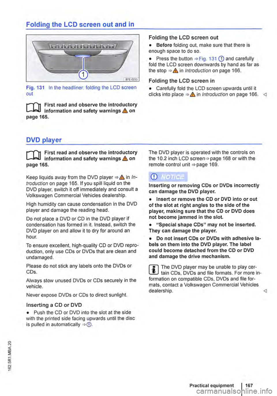
Fig. 131 In the headliner: folding the LCD screen out
r-111 First read and observe the introductory L-b.U information and safety warnings & on page 165.
DVD player
r-111 First read and observe the introductory L-b.U information and safety warnings & on page 165.
Keep liquids away from the DVD player & in In-troduction on page 165. If you spill liquid on the DVD player, switch it off immediately and consult a Volkswagen Commercial Vehicles dealership.
High humidity can cause condensation in the DVD player and damage the reading head.
Do not place a DVD or CD in the DVD player if condensation has formed in it. Instead, switch the DVD player on and allow it to dry for around an hour.
To ensure excellent, high-quality CD or DVD repro-duction, only use COs or DVDs that are clean and undamaged.
Please do not stick any labels onto the DVDs or COs.
Always stow unused DVDs or COs securely in the vehicle.
Never expose DVDs or COs to direct sunlight.
Inserting a CD or DVD
• Push the CD or DVD into the slot at the side with the printed side facing upwards until the disc is pulled in automatically
Folding the LCD screen out
• Before folding out. make sure that there is enough space to do so.
• Press the button 131 G) and carefully fold the LCD screen downwards by hand as far as the in Introduction on page 166.
Folding the LCD screen in
• Carefully fold the LCD screen upwards until it clicks into in Introduction on page 166.
CD
Inserting or removing COs or DVDs incorrectly can damage the DVD player.
• Insert or remove the CD or DVD into or out of the slot at right angles to the side of the player, making sure that the CD or DVD does not become jammed in the slot.
• "Special shape COs" may not be inserted. They can damage the player.
• Do not insert COs or DVDs with adhesive la-bels on them Into the DVD player. The label could become detached from the CD or DVD and damage the drive mechanism.
m The DVD player may be unable to play cer-L!J tain COs, DVDs and file formats. For more in-formation on compatible COs, DVDs and file for-mats, contact a Volkswagen Commercial Vehicles dealership.
Page 172 of 486
• Press the [ENTER! button to confirm your selec-tion.
• Press the [SETUP! button again to leave the main menu.
The following settings can be made in the subme-nus:
• Picture format.
• Camera perspective.
• Language.
• Subtitles.
• Screen saver.
• Saving the last item played.
Tachograph
o::D Introduction
This chapter contains information on the following subjects:
Notes on the tachograph . . . . . . . . . . . . . . . . . 172
The function and operation of the factory-fitted ta-chograph can be found in an additional operating manual delivered with the vehicle.
If you retro-fit a tachograph to the vehicle, ensure it complies with relevant legislation.
Additional information and warnings:
• Towing a trailer 139
• Accessories. modifications, repairs and renewal of parts 394
Notes on the tachograph
I""'""'J'n First read and observe the Introductory L-lo:.l.l Information given on page 172.
Location
Depending on the model, the factory-fitted tacho-graph could be located in the middle of the dash panel or in a console on the dash panel.
Time
For the time settings, refer to the additional operat-ing instructions for the tachograph.
Please note that in digital tachographs, the time must be displayed in local time. The time on the printouts is always given in UTC (Coordinated Uni-versal Time).
1721 Before the journey
• Various audio settings.
• Colour system.
• Playback control for video COs
• Parental lock 172.
• Reset to default settings.
• Password protection.
Childproof locks
This function is only available in the case of DVDs with restricted access for young people and chil-dren. This menu is used to specify whether a DVD with access restrictions is to be played or whether a password has to be entered first.
m Manipulation of the tachograph and its signal, l.!J and misuse of the tachograph discs can re-sult in prosecution.
The digital tachograph has a buffer battery to pre-vent data loss. The buffer battery can supply power for approx. one year without an external power supply. This function is used if, for example, the digital tachograph is removed from the vehicle and stored or if left in a vehicle with a battery fault or a flat battery.
Legal requirements
By law. the tachograph must be used in: