2010 VOLKSWAGEN TRANSPORTER ECU
[x] Cancel search: ECUPage 141 of 486

A WARNING (Continued)
• Never try to stop a trailer from snaking by Increasing your speed.
A WARNING
Accidents and severe injuries can occur if the maximum permitted draw bar weight is ex-ceeded.
• Never exceed the specified values.
A WARNING
The start/stop system must always be switch-ed off manually when a trailer Is to be towed with towing brackets that were not retrofitted by Volkswagen Commercial Vehicles. Other-wise faults can occur In the brake system, possibly resulting In accidents and serious Injuries.
Technical requirements
,...-.('n First read and observe the introductory 1--J,:.U information and safety warnings & on page 139.
If the vehicle is supplied with a factory-fitted tow-ing bracket it will already have the necessary tech-nical modifications and meet the statutory require-ments for towing a trailer.
Only use a towing bracket which is approved for the gross weight of the trailer you want to tow as a retrofit solution. The towing bracket must be suit-able for the vehicle and trailer and be securely bol-ted to the vehicle's chassis. Only a towing bracket with a removable ball coupling should be used. Al-ways check and follow the data provided by the towing bracket manufacturer. Never install a weight-distributing or load-balancing towing brack-et on the vehicle.
Towing brackets fitted to the rear bumper
Never fit a towing bracket to the rear bumper or to its fastenings. The towing bracket must not prevent the rear bumper from functioning correctly. Do not
A WARNING (Continued)
• Always switch off the start/stop system manually If a trailer is attached to a towing bracket that was not retrofitted by Volkswa-gen Commercial Vehicles.
m Always switch off the anti-theft alarm when a L!J trailer is being hitched or unhitched 43. The tilt sensor could otherwise trigger an alarm unnecessarily.
m In new vehicles, do not tow a trailer during L!J the first 1,000 km 394.
m Volkswagen Commercial Vehicles recom-L!J mends removing the ball coupling before driving without a trailer. The level of damage sus-tained during a rear-end collision could be greater for vehicles with a fitted ball coupling than for those without.
m By law, the ball coupling must be removed if L!J a trailer is not being towed if it obscures the number plate.
m In some models, the towing bracket is re-L!J qui red for towing vehicles. For this reason, the towing bracket ball coupling should be stored in the vehicle at all times.
Engine cooling system
There is an increased load on the engine and the cooling system when towing a trailer. The cooling system must contain sufficient coolant and be able to cope with the extra load added by the trailer.
Trailer brake
If the trailer is equipped with its own brake system, comply with the relevant regulations. The trailer's brake system must never be connected to the ve-hicle brake system.
Emergency breakaway cable
Always use safety chains between your vehicle and the trailer 144.
Trailer rear lights
The rear lights on the trailer must meet legal re-quirements 144.
Transporting items 1141
Page 143 of 486
Key to Fig. 113:
Q) Cap
® Ball coupling
@ Retaining balls
@ Catch for locking mechanism
® Shank
® Centring device
0 Handwheel
® Keys
® Cover
® Gap (pre-tensioned ball coupling)
® Green marking on the ball coupling
@ Green marking on handwheel
@ Red marking on handwheel
Step 1: preparations
• Before using the ball coupling for the first time, make a note of the number stamped on the key. This can be used if you need to acquire a replace-ment key.
• Remove the cap from the mounting.
• Check to ensure that the mounting, handwheel 0. shank® and retaining balls@ of the ball cou-pling are all clean and not damaged Clean as necessary.
Step 2: setting the ball coupling to the "ready" position
The ball coupling cannot be fitted properly unless the spring mechanism inside the ball joint is in the ready position.
• Take the ball coupling in your left hand.
• Remove the cover® from the lock and insert the key ® into the lock.
• Turn the key clockwise.
• Use your right hand to pull out the handwheel 0 in the direction of arrow 1 and keep it in this po-
• Turn the handwheel 0 in the direction of arrow 2 until it engages. The ball coupling is now in the ready position. The red marking @on the hand-wheel must point towards the green marking ® on the ball coupling. The handwheel is clearly visible in front of the ball coupling. The distance between the two is approximately 4 mm @.
• Check to see whether all retaining balls @can be pressed fully into the ball coupling mount @.
Step 3: attaching the pre-tensioned ball coupling to the vehicle
Do not touch the handwheel once the ball coupling has been pre-tensioned. When engaged, the hand-wheel will spring back to its original position and could cause injury = &.
• Guide the pre-tensioned ball coupling into the mounting pipe from below.
• Push the ball coupling firmly upwards until it en-gages. Both of the centring devices ® must en-gage in the insertion point on the vehicle.
• The handwheel has now returned to its original position. There is no longer a gap between the handwheel and the ball coupling.
• Turn the key ® anticlockwise in the handwheel and remove it.
• If the setting is correct, you will not be able to turn the handwheel or pull it out.
• Put the cover® over the lock and place the key in the vehicle toolkit.
Step 4: safety check
Check to see whether the ball coupling is attached properly:
• The green marking@ on the handwheel must point towards the green marking @ on the ball coupling.
• The handwheel must rest on the ball coupling and there may be no gap between them.
• Shake the ball coupling or pull it down with some force. lt must sit firmly in the mounting = &.
• The lock must be locked and the key removed. The cover must be fitted over the lock in the hand-wheel.
A wARNING
Improper fitting of the ball coupling can cause injuries and accidents.
• Only use the ball coupling when it is fitted properly.
• If the smallest diameter on the ball cou-pling ® is smaller than 49 mm, do not use the towing bracket.
• The ball coupling is heavy. When checking whether it is secure, the ball coupling could fall off and cause injuries.
• Do not touch the handwheel once the ball coupling has been pre-tensioned. When the ball coupling is pressed into the mounting, the handwheel will spring back to its original position. ..,
Transporting items 1143
Page 144 of 486
A WARNING (Continued)
• If the ball coupling will not fit properly, the towing bracket should be checked by a quali-fied workshop.
• Do not use the towing bracket If the ball coupling does not engage properly or if you are unable to set it to the "ready" position.
• Do not use the towing bracket if you are unable to remove the key from the handwheel once the ball coupling has been mounted. This means that ball coupling Is not locked properly.
Removing the ball coupling
r--T'n First read and observe the Introductory L-J.:.IJ information and safety warnings & on page 139.
• Unhitch the trailer => &.
• Remove the cover =>Fig. 113 ®from the lock on the handwheel.
• Insert the key® into the lock and turn it clock-wise.
• Hold the ball coupling tightly in your left hand =>&.
• Use your right hand to pull out the handwheel 0 in the direction of arrow 1 and keep it in this po-sition.
• Turn the handwheel 0 in the direction of arrow 2 until it engages.
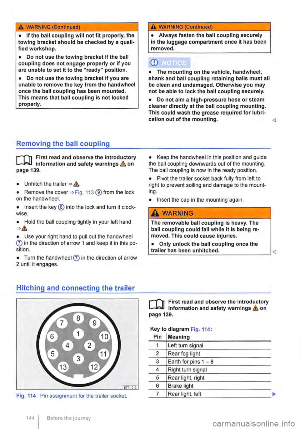
Hitching and connecting the trailer
Fig. 114 Pin assignment for the trailer socket.
1441 Before the journey
A WARNING (Continued)
• Always fasten the ball coupling securely In the luggage compartment once it has been removed.
CD
• The mounting on the vehicle, handwheel, shank and ball coupling retaining balls must all be clean and undamaged. Otherwise you may not be able to lock the ball coupling securely.
• Do not aim a high-pressure hose or steam cleaner directly at the ball coupling mounting. This could wash the grease required for lubri-cation out of the mounting.
• Pivot the trailer socket back fully from left to right to prevent soiling and damage to the mount-ing.
• Insert the cap in the mounting again.
A WARNING
The removable ball coupling Is heavy. The ball coupling could fall while it Is being re-moved. This could cause Injuries.
• Only unlock the ball coupling once the L-tr_a_ile_r_h_a_s __ be_e_n __ u_n_hi_tc_h_e_d_. ____________
r--T'n First read and observe the Introductory L-J.:.IJ information and safety warnings & on page 139.
Key to diagram Fig. 114:
Pin Meaning
1 Left turn signal
2 Rear fog light
3 Earth for pins 1 -8
4 Right turn signal
5 Rear light, right
6 Brake light
7 Rear light, left
Page 146 of 486
m If the vehicle battery charge level is low, the W electrical connection to the trailer will be in-terrupted automatically.
Loading the trailer
ill1 First read and observe the introductory L-W.! information and safety warnings & on page 139.
Trailer weight and drawbar load
The trailer weight is the weight that the vehicle can pull &. The drawbar load is the weight that the towing bracket exerts on the ball coupling vertically from above.
The figures for trailer weights and draw bar weights that are given on the data plate of the towing bracket are for certification purposes only. The cor-rect values for your specific model, which may be lower than these figures, are given in the vehicle registration documents. All data in the official vehi-cle documents take precedence over these data.
In the interest of road safety, Volkswagen Commer-cial Vehicles recommends that you always trans-port the maximum drawbar load. The response of the trailer on the road will be poor if the drawbar load is too small.
The drawbar load increases the weight on the rear axle and reduces the maximum load level as a re-sult.
Gross combination weight rating
The combination weight is made up of the actual weight of the loaded vehicle and of the loaded trail-er.
Loading the trailer
The weight of the load should be distributed even-ly. The maximum permitted drawbar load should be utilised. Do not place the load only at the front or the rear of the trailer:
Towing a trailer
ill1 First read and observe the introductory L-W.! information and safety warnings & on page 139.
146 Before the Journey
m When the engine is running, electrical con-w sumers in the trailer are supplied with voltage via the electrical connection (pin 9 and pin 10 of the trailer socket).
• Secure all loads on the trailer properly.
Tyre pressure
Follow the trailer manufacturer's recommendations concerning the tyre pressure for the trailer tyres.
When towing a trailer, inflate the wheels on the towing vehicle with the maximum permitted tyre pressure 367.
A WARNING
Accidents and serious injuries can occur if you exceed the vehicle's maximum permitted gross axle weight rating, drawbar load, gross vehicle weight rating or gross combination weight rating.
• Never exceed the specified values .
• Never let the actual weights at the front and rear axles exceed the gross axle weight ratings. Never exceed the permissible gross vehicle weight for the vehicle with weight at the front and rear of the vehicle.
A wARNING
Loads that may slide can severely Impair sta-bility and driving safety, which can cause ac-cidents and severe injuries.
• Always load trailers correctly .
• Always secure loads using suitable and undamaged securing straps.
Headlight adjustment
Towing a trailer can raise the front end of the vehi-cle enough for the dipped beam to blind other road users. Use the headlight range control to lower the
Page 150 of 486
Practical equipment
Stowage area
o::n Introduction
This chapter contains information on the following subjects:
Stowage compartments on the dash panel . . 151 Stowage compartment on the front passenger side . . . . . . . . . . . . . . . . . . . . . . . . . 151 Other stowage compartments . . . . . . . . . . . . . 152
Only use stowage compartments to stow light or smaller objects.
A factory-fitted AUX-IN socket or the USB sock-may be located in the storage compartment on the front passenger side =>Booklet Radio, provi-sion for mobile telephone, infotainment system, navigation system.
Additional information and warnings:
• Seat functions, front => page 69
• Seat functions, rear =>page 72
• Stowage =>page 150
• Drink holder => page 153
• Central table =>page 155
• Seat functions, rear. Business =>page 182
• Seat functions, rear, California =>page 193
• Cleaning and caring for the interior =>page 388
A WARNING
Loose objects may be flung through the vehi-cle Interior In the event of a sudden driving or braking manoeuvre. This can cause serious injury and can also lead to loss of control of the vehicle.
• Do not stow any pets or any hard, heavy or sharp objects In the vehicle's open stow-age areas, on the dash panel, on the shelf be-hind the rear seats, or in items of clothing and bags in the vehicle Interior.
• Store any objects in open stowage com-partments in such a way that they do not project over the edges of the stowage com-partment.
• Always keep stowage compartments with a lid closed while the vehicle is in motion.
150 I Before the journey
A WARNING
External devices in the vehicle that are not properly secured can be flung though the in-terior and cause Injuries, if there is a sudden driving or braking manoeuvre, or in the event of an accident.
• You should never position or attach an ex-ternal device on a door, on the windscreen or above or near to the areas marked "AIRBAG" on the steering wheel, the dash panel and the seat backrests, or between these areas and the vehicle occupants. External devices can cause serious Injury in an accident, especial-ly when the alrbags deploy.
A WARNING
Objects in the driver footwell can hinder ped-al operation. This can lead to loss of control of the vehicle and increase the risk of serious injury.
• Please ensure that all pedals can always be operated without any hindrance.
• The foot mats must always be properly se-cured in the footwell.
• No additional foot mats or other floor cov-erings should be placed over the fitted foot mat.
• Ensure that no objects can enter the driv-er footwell while the vehicle Is in motion.
• If there are any objects in the footwell, re-move them when the vehicle is parked.
A WARNING
Cigarette lighters in the vehicle could be damaged or accidentally lit. This could lead to serious burns and other Injuries.
• Before adjusting the seats always make sure that there Is no lighter on or near the moveable parts of the seat.
• Before closing stowage areas or compart-ments always ensure that there Is no lighter in the way. 11>
Page 153 of 486
A WARNING
Objects that are not secured, or are secured Incorrectly, can cause serious Injuries In the event of a sudden driving or braking manoeu·
Torch behind front passenger seat
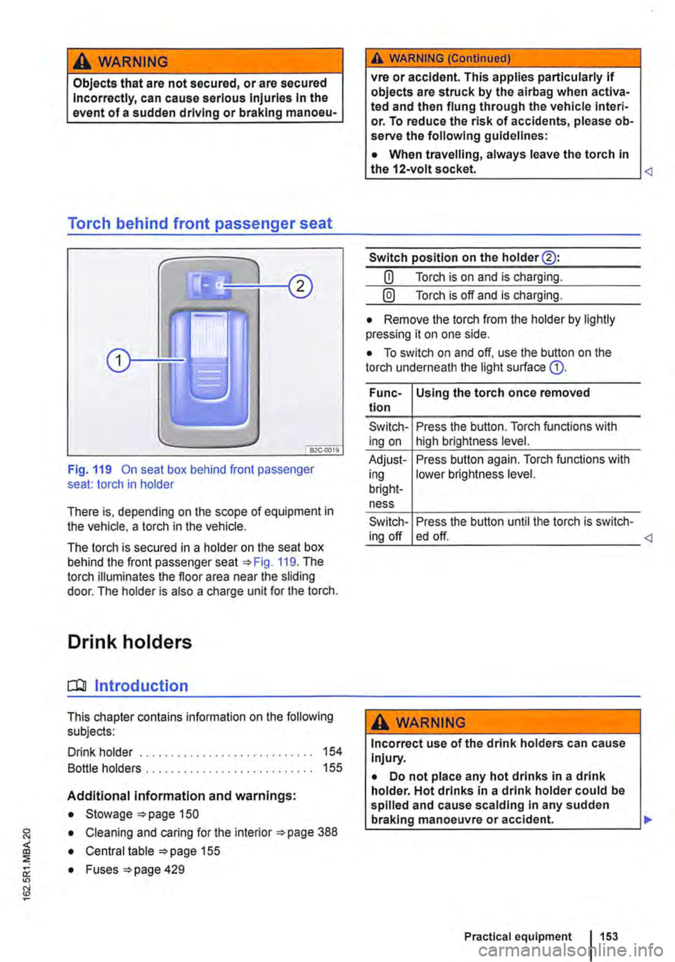
Fig. 119 On seat box behind front passenger seat: torch in holder
There is, depending on the scope of equipment in the vehicle, a torch in the vehicle.
The torch is secured in a holder on the seat box behind the front passenger seat 119. The torch illuminates the floor area near the sliding door. The holder is also a charge unit for the torch.
Drink holders
CQJ Introduction
This chapter contains information on the following subjects:
Drink holder . . . . . . . . . . . . . . . . . . . . . . . . . . . . 154
Bottle holders . . . . . . . . . . . . . . . . . . . . . . . . . 155
Additional information and warnings:
• Stowage 150
• Cleaning and caring for the interior 388
• Central table 155
0: • Fuses =>page 429
"'
A WARNING (Continued)
vre or accident. This applies particularly if objects are struck by the airbag when activa-ted and then flung through the vehicle interi· or. To reduce the risk of accidents, please ob-serve the following guidelines:
• When travelling, always leave the torch in the 12-volt socket.
Switch position on the holder@:
CD Torch is on and is charging.
@) Torch is off and is charging.
• Remove the torch from the holder by lightly pressing it on one side.
• To switch on and off, use the button on the torch underneath the light surface G).
Func-Using the torch once removed tion
Switch-Press the button. Torch functions with ing on high brightness level.
Adjust-Press button again. Torch functions with ing lower brightness level. bright-ness
Switch-Press the button until the torch is switch-ing off ed off.
A WARNING
Incorrect use of the drink holders can cause Injury.
• Do not place any hot drinks in a drink holder. Hot drinks in a drink holder could be spilled and cause scalding In any sudden braking manoeuvre or accident. .,.
Practical equipment 153
Page 155 of 486
Opening the drink holder in the centre console
• Press onto drink holder "'Fig. 120 G). The drink holder will then open automatically.
• Push the holder® slightly to the side and place the bottle or can into the drink holder.
Opening and closing the drink holder in the rear side trim panel
• Press button "'Fig. 121 G). The drink holder will then open automatically.
Bottle holders
1"'111 First read and observe the introductory L-J,::.ll information and safety warnings & on page 153.
Depending on the vehicle equipment level, the bot-tle holders may be found at the following locations:
• In the front door trims
• In the lower section of the centre console
• In the side trim panels in the living area.
• In the central table
Opening and closing the bottle holder in the centre console
• To open, pull the handle of the bottle holder. The bottle holder will then open automatically.
• To close, push the bottle holder until it clicks in-to place.
Tables
o:::n Introduction
This chapter contains information on the following subjects:
Folding table in the side panel . . . . . . • . . . . . . 156 Central table . . . . . . . . . . . . 156
Additional information and warnings:
• Stowage "'page 150
• Drink holder 153
Opening the drink holder in the central table
• Press lhe symbol i on the cover of the drink holder and pull the drink holder out fully.
Closing the drink holder
• Remove the bottle or can.
• Push the drink holder in until it engages secure-
Bottle holder in the central table
The bottle holder in the central table can be ac-cessed after the table module has been raised.
m The bottle holder in the centre console must W be removed to gain access to the fuses in Multivan with left-hand drive 429.
A WARNING
Improper use of the tables could cause seri-ous injury.
• Never use the tables while the vehicle is in motion.
• All tables must be securely stowed while the vehicle is In motion.
• Never sit or stand on the tables.
CD
Never place hot objects, such as pots or pans, on the tables. Such objects could damage these surfaces.
Practical equipment 155
Page 156 of 486
Folding table in the side panel
l
1---c:J--'
t,J
171·0160
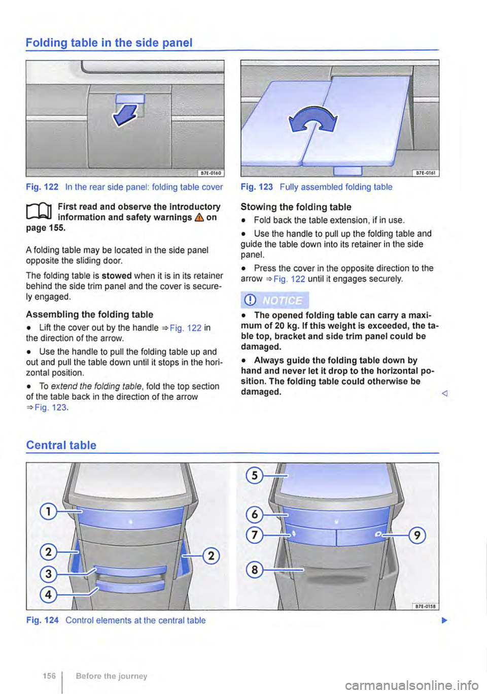
Fig. 122 In the rear side panel: folding table cover
f"'"""'(""'n First read and observe the Introductory Information and safety warnings & on page 155.
A folding table may be located in the side panel opposite the sliding door.
The folding table is stowed when it is in its retainer behind the side trim panel and the cover is secure-ly engaged.
Assembling the folding table
• Lift the cover out by the handle 122 in the direction of the arrow.
• Use the handle to pull the folding table up and out and pull the table down until it stops in the hori-zontal position.
• To extend the folding table, fold the top section of the table back in the direction of the arrow 123.
Central table
Fig. 124 Control elements at the central table
156 I Before the journey
Fig. 123 Fully assembled folding table
Stowing the folding table
• Fold back the table extension, if in use.
• Use the handle to pull up the folding table and guide the table down into its retainer in the side panel.
• Press the cover in the opposite direction to the arrow 122 until it engages securely.
CD
• The opened folding table can carry a maxi-mum of 20 kg. If this weight is exceeded, theta-ble top, bracket and side trim panel could be damaged.
• Always guide the folding table down by hand and never let it drop to the horizontal po-sition. The folding table could otherwise be damaged.