2010 SUZUKI SX4 trans axle
[x] Cancel search: trans axlePage 224 of 297
7-19INSPECTION AND MAINTENANCE
80J23-03E
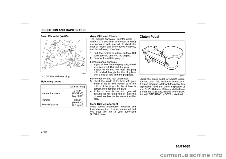
Rear differential (i-AWD)
80J015
(1) Oil filler and level plug
Tightening torque
Gear Oil Level CheckThe manual transaxle, transfer gears (i-
AWD CVT) and rear differential (i-AWD)
are lubricated with gear oil. To check the
gear oil level in any of the above locations,
use the following procedure:
1) Park the vehicle on a level surface. Set
parking brake and stop the engine.
2) Remove the oil filler plug (1).
For the manual transaxle;
3) If gear oil flow from the plug hole, the oil
level is correct. Reinstall the plug.
If gear oil do not flow from the plug
hole, add oil through the filler plug hole
until a little oil flow from the plug hole.
For the transfer and rear differential;
3) Check the inside of the hole with your
finger. If the oil level comes up to the
bottom of the plug hole, the oil level is
correct. If so, reinstall the plug.
4) If the oil level is low, add gear oil
through the filler plug hole (1) until the
oil level reaches the bottom of the filler
hole.Gear Oil ReplacementSince special procedures, materials and
tools are required, it is recommended that
you trust this job to your authorized
SUZUKI dealer.
Clutch Pedal
80J004
Check the clutch pedal for smooth opera-
tion and clutch fluid level from time to time.
If clutch dragging is felt with the pedal fully
depressed, have the clutch inspected by
your SUZUKI dealer. If the clutch fluid level
is near the “MIN” line, fill it up to the “MAX”
line with SAE J1703 or DOT3 brake fluid. Oil Filler Plug
Manual transaxle27 Nm
(19.5 lb-ft)
(2.7 kg-m)
Transfer 23 Nm
(16.6 lb-ft)
(2.3 kg-m) Rear differential
(1)
Page 225 of 297
7-20
INSPECTION AND MAINTENANCE
80J23-03E
Continuously Variable
Transaxle (CVT) FluidSpecified FluidUse a CVT fluid SUZUKI CVT FLUID
GREEN-1 or Shell GREEN-1V.Fluid Level CheckYou must check the fluid level with the CVT
fluid at normal operating temperature.
To check the fluid level:
1) To warm up the transaxle fluid, drive the
vehicle or idle the engine until the tem-
perature gauge indicates normal oper-
ating temperature.
2) Then drive for ten more minutes.
NOTE:
Do not check the fluid level if you have just
driven the vehicle for a long time at high
speed, or if you have driven in city traffic inhot weather. Wait until the fluid cools down
(about 30 minutes), or the fluid level indica-
tion will not be correct.
3) Park your vehicle on level ground.
4) Apply the parking brake and then start
the engine in “P” (Park). Let it idle for
two minutes and keep it running during
the fluid level check.
5) With your foot on the brake pedal, move
the gearshift lever through each gear,
pausing for about three seconds in
each range. Then move it back to the
“P” (Park) position.
75F08680J2071
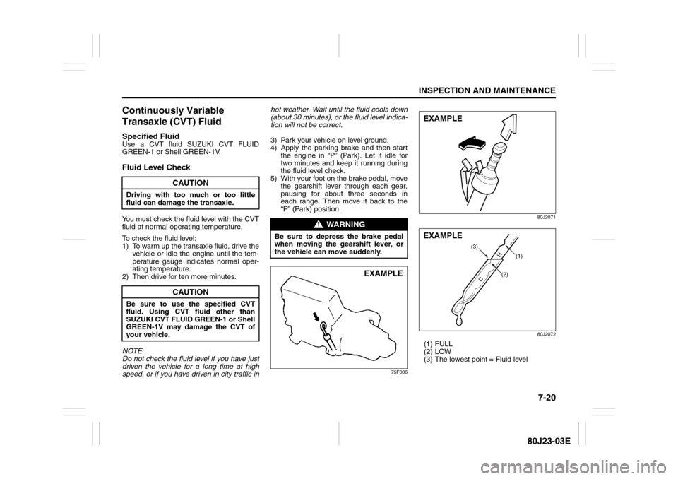
80J2072
(1) FULL
(2) LOW
(3) The lowest point = Fluid level
CAUTION
Driving with too much or too little
fluid can damage the transaxle.
CAUTION
Be sure to use the specified CVT
fluid. Using CVT fluid other than
SUZUKI CVT FLUID GREEN-1 or Shell
GREEN-1V may damage the CVT of
your vehicle.
WARNING
Be sure to depress the brake pedal
when moving the gearshift lever, or
the vehicle can move suddenly.
EXAMPLE
EXAMPLE
(2)H
C
(1) (3)
EXAMPLE
Page 226 of 297
7-21INSPECTION AND MAINTENANCE
80J23-03E
6) The handle of the CVT fluid dipstick is
colored red or orange for easy identifi-
cation.
Remove the dipstick, clean it and push
it back in until the cap seats. Pull out
the dipstick and read the fluid level.
The fluid level should be between the
two marks in the “HOT” range on the
dipstick.
7) Add just enough specified fluid through
the dipstick hole to fill the transaxle to
the proper level. It takes only 0.6 liters
(1.27 US pt) for CVT to raise the level
from “LOW” to “FULL”.Deterioration Checking or Chang-
ing OilSince special procedures, materials and
tools are required to check the deteriora-
tion of CVT oil or change, it is recom-
mended that you trust this job to your
authorized SUZUKI dealer.
BrakesBrake Fluid
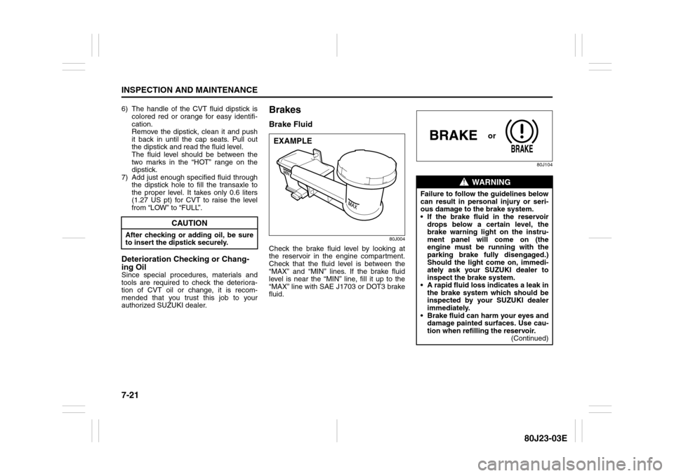
80J004
Check the brake fluid level by looking at
the reservoir in the engine compartment.
Check that the fluid level is between the
“MAX” and “MIN” lines. If the brake fluid
level is near the “MIN” line, fill it up to the
“MAX” line with SAE J1703 or DOT3 brake
fluid.
80J104
CAUTION
After checking or adding oil, be sure
to insert the dipstick securely.
EXAMPLE
WARNING
Failure to follow the guidelines below
can result in personal injury or seri-
ous damage to the brake system.
If the brake fluid in the reservoir
drops below a certain level, the
brake warning light on the instru-
ment panel will come on (the
engine must be running with the
parking brake fully disengaged.)
Should the light come on, immedi-
ately ask your SUZUKI dealer to
inspect the brake system.
A rapid fluid loss indicates a leak in
the brake system which should be
inspected by your SUZUKI dealer
immediately.
Brake fluid can harm your eyes and
damage painted surfaces. Use cau-
tion when refilling the reservoir.
(Continued)
or
Page 229 of 297
7-24
INSPECTION AND MAINTENANCE
80J23-03E
Power Steering (if equipped)
54G225
(1) UPPER
(2) LOWER
Check the steering box case, vane pump
and hose connections for leaks or damage.Power Steering FluidCheck the fluid level by looking at the res-
ervoir in the engine compartment when the
fluid is cold (about room temperature).
Check that the fluid level is between the (1)
and (2) lines. If the fluid level is near the (2)
line, fill it up to the (1) line with an auto-
matic transaxle fluid equivalent to ATF
DEXRON
®-II (Esso JWS 2326) or
DEXRON®-III. Do not overfill.
TiresFor safe operation of your vehicle, it is
important that the tires be the correct
type and size, in good condition, and
properly inflated. Be sure to follow the
requirements and recommendations in
this section.
Tire Sidewall Labeling
Useful information about a tire is
molded into its sidewall. The example
below shows a typical passenger car
tire.
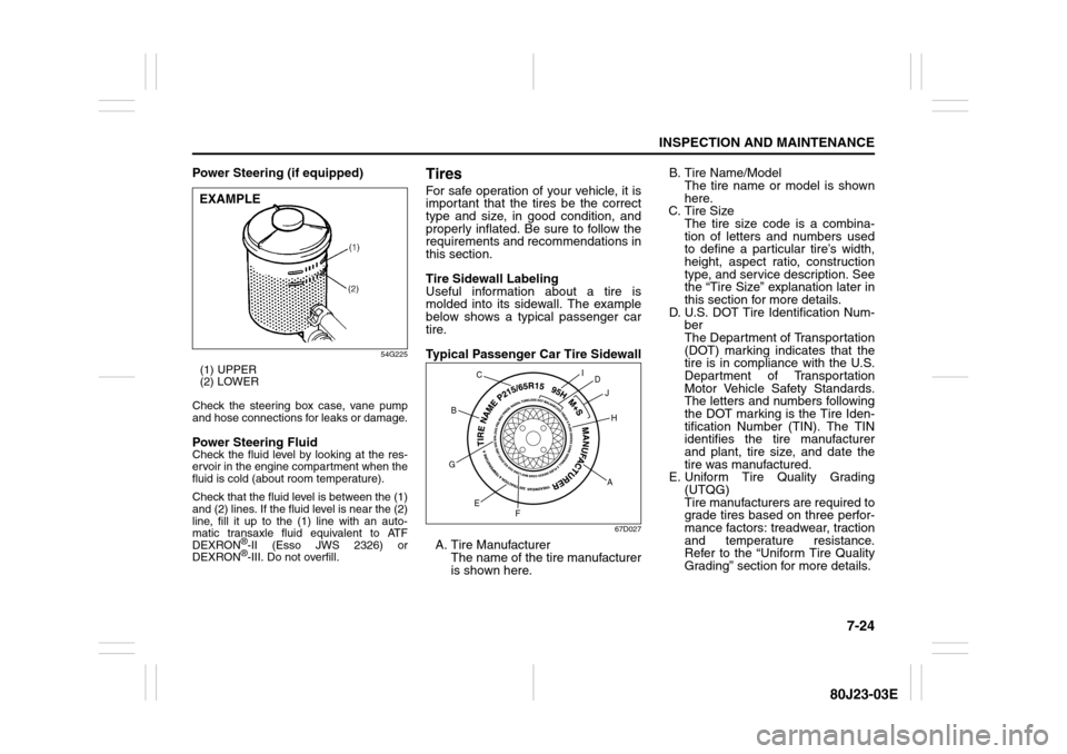
Typical Passenger Car Tire Sidewall
67D027
A. Tire Manufacturer
The name of the tire manufacturer
is shown here.B. Tire Name/Model
The tire name or model is shown
here.
C. Tire Size
The tire size code is a combina-
tion of letters and numbers used
to define a particular tire’s width,
height, aspect ratio, construction
type, and service description. See
the “Tire Size” explanation later in
this section for more details.
D. U.S. DOT Tire Identification Num-
ber
The Department of Transportation
(DOT) marking indicates that the
tire is in compliance with the U.S.
Department of Transportation
Motor Vehicle Safety Standards.
The letters and numbers following
the DOT marking is the Tire Iden-
tification Number (TIN). The TIN
identifies the tire manufacturer
and plant, tire size, and date the
tire was manufactured.
E. Uniform Tire Quality Grading
(UTQG)
Tire manufacturers are required to
grade tires based on three perfor-
mance factors: treadwear, traction
and temperature resistance.
Refer to the “Uniform Tire Quality
Grading” section for more details.
EXAMPLE
AH B
G
E
FD
J I
C
Page 239 of 297
7-34
INSPECTION AND MAINTENANCE
80J23-03E
trailer). Contact your dealer for further
information.
Actual weight of the loaded vehicle
and actual loads at the front and rear
axles can only be determined by
weighing the vehicle using a vehicle
scale. To measure the weight and
load, try making your vehicle to a high-
way weighing station, shipping com-
pany or inspection station for trucks,
etc. Compare these weights to the
GVWR and GAWR (front and rear)
listed on the Safety Certification Label.
If the gross vehicle weight or the load
on either axle exceeds these ratings,
you must remove enough weight to
bring the load down to the rated
capacity.Steps for Determining Correct Load
Limit
1) Locate the statement “The com-
bined weight of occupants and
cargo should never exceed XXX kg
or XXX lbs” on your vehicle’s plac-
ard.
2) Determine the combined weight of
the driver and passengers that will
be riding in your vehicle.
3) Subtract the combined weight of
the driver and passengers from
XXX kg or XXX lbs.
4) The resulting figure equals the
available amount of cargo and lug-
gage load capacity. For example, if
the “XXX” amount equals 1400 lbs
and there will be five 150 lb passen-
gers in your vehicle, the amount of
available cargo and luggage load
capacity is 650 lbs (1400 – 750 (5 x
150) = 650 lbs).
5) Determine the combined weight of
luggage and cargo being loaded on
the vehicle. That weight may not
safely exceed the available cargo
and luggage load capacity calcu-
lated in Step 4.
6) If your vehicle will be towing a
trailer, load from your trailer will be
transferred to your vehicle. Consult
this manual to determine how this
reduces the available cargo and lug-
gage load capacity of your vehicle.
WARNING
Never overload your vehicle. Over-
loading your vehicle can cause
damage to your tires and lead to
poor steering and braking which
can result in an accident. The
gross vehicle weight (sum of the
weights of the loaded vehicle,
driver and passengers) must
never exceed the Gross Vehicle
Weight Rating (GVWR) listed on
the Safety Certification Label. In
addition, never distribute a load so
that the weight on either the front
or rear axle exceeds the Gross
Axle Weight Rating (GAWR) listed
on the Safety Certification Label.
WARNING
Always distribute cargo evenly.
To avoid personal injury or
damage to your vehicle, always
secure cargo to prevent it from
shifting if the vehicle moves
suddenly.
Place heavier objects on the
floor and as far forward in the
cargo area as possible. Never
pile cargo higher than the top of
the seatbacks.
Page 242 of 297

7-37INSPECTION AND MAINTENANCE
80J23-03E
The main fuse, primary fuses and some of
the individual fuses are located in the
engine compartment. If the main fuse
blows, no electrical component will func-
tion. If a primary fuse blows, no electrical
component in the corresponding load
group will function. When replacing the
main fuse, a primary fuse or an individual
fuse, use a genuine SUZUKI replacement.
To remove a fuse, use the fuse puller pro-
vided in the fuse box. The amperage of
each fuse is shown in the back of the fuse
box cover.
60A243
NOTE:
Make sure that the fuse box always carries
spare fuses. MAIN FUSE / PRIMARY FUSE
(1) 80A All electric load
(2) 50APower window, Ignition,
Wiper, Starter
(3) 50ATail light, Rear defogger,
Door lock, Hazard/Horn,
Dome
(4) – Blank
(5) – Blank
(6) 15A Head light (Right) fuse
(7) 15A Head light (Left) fuse
(8) 20A Front fog light fuse
(9) – Blank
(10) 40A ABS motor fuse
(11) 30A Radiator fan fuse
(12) 30A ABS solenoid fuse
(13) 30A Starting motor fuse
(14) 50A Ignition switch fuse
(15) 30A Blower fan fuse
(16) 20A Air compressor fuse
(17) 15A Throttle motor fuse
(18) 15A Automatic transaxle fuse
(19) 15A Fuel injection fuse
(20) – Automatic transaxle relay
(21) – Air compressor relay
(22) – Fuel pump relay
(23) – Condenser fan relay
(24) – Front fog light relay
(25) – Throttle motor relay
(26) – FI MAIN relay
(27) – Starting motor relay
(28) – Radiator fan relay
(29) – Radiator fan relay 2
(30) – Radiator fan relay 3
WARNING
If the main fuse or a primary fuse
blows, be sure to have your vehicle
inspected by an authorized SUZUKI
dealer. Always use a genuine SUZUKI
replacement. Never use a substitute
such as a wire even for a temporary
fix, or extensive electrical damage
and a fire can result.
BLOWNOK
Page 259 of 297
8-2
EMERGENCY SERVICE
80J23-03E
Jacking Instructions
75F062
1) Place the vehicle on level, hard ground.
2) Set the parking brake firmly and shift
into “P” (Park) if your vehicle has a CVT,
or shift into “R” (Reverse) if your vehicle
has a manual transaxle.
3) Turn on the hazard warning flasher if
your vehicle is near traffic.4) Block the front and rear of the wheel
diagonally opposite of the wheel being
lifted.
5) Place the spare wheel near the wheel
being lifted as shown in the illustration
in case that the jack slips.
54G253
WARNING
The jack should be used only to
change wheels. It is important to read
the jacking instructions in this sec-
tion before attempting to use the
jack.
WARNING
After using the jack, jack handle and
wheel wrench, be sure to stow them
securely or they can cause injury if
an accident occurs.
WARNING
Be sure to shift into “P” (Park) for a
CVT vehicle, or into “R” (Reverse)
for a manual transaxle vehicle
when you jack up the vehicle.
Never jack up the vehicle with the
transaxle in “N” (Neutral). Other-
wise, an unstable jack may cause
an accident.
Trailer Towing: 5, 11, 13
Towing Your Vehicle (recreational towing): 13
Page 261 of 297

8-4
EMERGENCY SERVICE
80J23-03E
Changing WheelsTo change a wheel, use the following pro-
cedure:
1) Remove the jack, tools and spare wheel
from the vehicle.
2) Loosen, but do not remove the wheel
nuts.
3) Jack up the vehicle (follow the jacking
instructions in this section).
4) Remove the wheel nuts and wheel.
5) Before installing the new wheel, clean
any mud or dirt off from the surface of
the wheel and hub with a clean cloth.
Clean the hub carefully; it may be hot
from driving.
6) Install the new wheel and replace the
wheel nuts with their cone shaped end
facing the wheel. Tighten each nut
snugly by hand until the wheel is
securely seated on the hub.
81A057
7) Lower the jack and fully tighten the nuts
in a crisscross fashion with a wrench as
shown in the illustration.
Full Wheel Cover (if equipped)
60G309
(1) or (2) Flat end tool
Your vehicle includes two tools, a wheel
brace and a jack crank, one of which has a
flat end.
Use the tool with the flat end to remove the
full wheel cap, as shown above.
54G117
When installing the cover, make sure that it
is positioned so that it does not cover or
foul the air valve.
WARNING
Be sure to shift into “P” (Park) in
CVT, or shift into “R” (Reverse) in
manual transaxle when you jack up
the vehicle.
Never jack up the vehicle with the
transaxle in “N” (Neutral). Other-
wise, unstable jack may cause an
accident.
Wheel tightening torque
85 Nm (61.5 lb-ft, 8.5 kg-m)
WARNING
Use genuine wheel nuts and tighten
them to the specified torque as soon
as possible after changing wheels.
Incorrect wheel nuts or improperly
tightened wheel nuts may come
loose or fall off, which can result in
an accident. If you do not have a
torque wrench, have the wheel nut
torque checked by an authorized
SUZUKI dealer.
EXAMPLEEXAMPLE
Towing Your Vehicle (recreational towing): 13