2010 SUZUKI SX4 radio
[x] Cancel search: radioPage 106 of 297
3-5OPERATING YOUR VEHICLE
80J23-03E
If you leave any of the doors open with the
ignition switch in the “ACC” position for a
while (and no key inserted), the engine
may not start when you turn the ignition
switch to “START”. If the engine does not
start, close all doors completely or turn the
ignition switch back to the “LOCK” position,
then start the engine.
The ignition switch has the following four
positions:
LOCK (1)
This is the normal parking position. It is the
only position in which the key can be
removed. It locks the ignition, and prevents
normal use of the steering wheel.
For vehicles with a CVT, the gearshift lever
must be in the “P” (Park) position to turn
the key to the “LOCK” position.
To release the steering lock, turn the igni-
tion switch clockwise to one of the other
positions. If you have trouble turning the
ignition switch to unlock the steering, try
turning the steering wheel slightly to the
right or left while turning the switch.
Manual transaxle vehicle
You must push in the ignition switch to
turn it from the “LOCK” position to the
“ACC” position. To return to the “LOCK”
position from the “ACC” position, turn the
ignition switch counterclockwise while
pushing in the switch.CVT vehicle
To turn the ignition switch, push the
switch.
ACC (2)
Accessories such as the radio can oper-
ate, but the engine is off.
ON (3)
This is the normal operating position. All
electrical systems are on.
START (4)
This is the position for starting the engine
using the starter motor. The switch should
be released from this position as soon as
the engine starts.
Ignition switch reminder
(When using the keyless start system)
A buzzer sounds intermittently to remind
you to return the ignition switch to the
“LOCK” position if it is in the “ACC” position
when the driver’s door is opened.You can also turn the ignition switch by
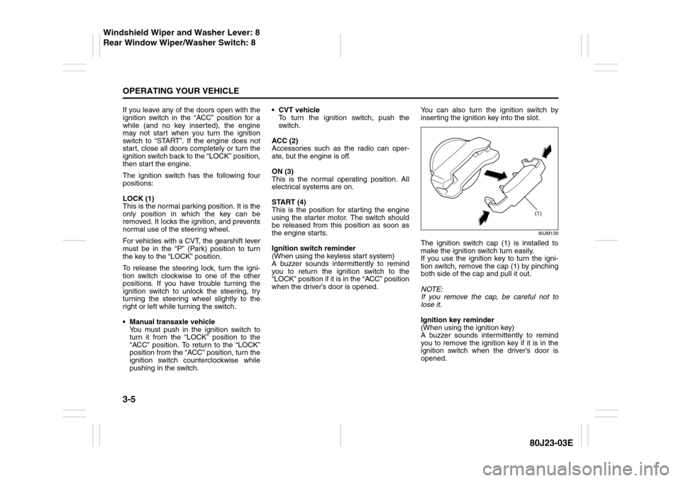
inserting the ignition key into the slot.
80JM139
The ignition switch cap (1) is installed to
make the ignition switch turn easily.
If you use the ignition key to turn the igni-
tion switch, remove the cap (1) by pinching
both side of the cap and pull it out.
NOTE:
If you remove the cap, be careful not to
lose it.
Ignition key reminder
(When using the ignition key)
A buzzer sounds intermittently to remind
you to remove the ignition key if it is in the
ignition switch when the driver’s door is
opened.
(1)
Windshield Wiper and Washer Lever: 8
Rear Window Wiper/Washer Switch: 8
Page 130 of 297

3-29OPERATING YOUR VEHICLE
80J23-03E
When you turn off the engine, however, the
malfunction indicator resets. It takes about
ten minutes after restarting the engine for
the malfunction to be detected again and
for the light to start flashing.
TPMS LimitationsThe tire pressure monitoring system may
not function properly under certain circum-
stances. In the following situations, the low
tire pressure warning light may come on
and remain on or may blink.
When you replace a flat tire with the
spare tire.
When you include the spare tire during a
tire rotation.
When the TPMS sensor is damaged dur-
ing a tire replacement or liquid sealants
are used to repair a flat tire. When the TPMS sensor’s electronic sig-
nal is disturbed in one of the following
ways:
– Electric devices or facilities using simi-
lar radio wave frequencies are nearby.
– A lot of snow or ice covers the vehicle,
in particular, around the wheels or
wheel housings.
– Snow tires or tire chains are used.
When you use non-genuine SUZUKI
wheels or tires.
Replacing Tires and/or WheelsIf you get a flat tire, Suzuki recommends
that you have an authorized SUZUKI
dealer mount a new tire on the wheel that
had the flat tire, and reinstall this tire on the
vehicle in place of the spare. The TPMS is
already set up to recognize the ID code of
the original wheel, and normal TPMS oper-
ation will be restored.
If you need to replace original wheels on
your vehicle, your dealer must make sure
that TPMS sensors are installed in the new
wheels and must set up the TPMS to rec-
ognize the new sensors.
NOTE:
A TPMS sensor is not installed in the spare
tire. You should use the spare tire only in
an emergency situation, and should
replace the spare tire as soon as possible
to restore normal TPMS operation.
WARNING
When the malfunction indicator is
illuminated, the system may not be
able to detect or signal low tire pres-
sure as intended. TPMS malfunctions
may occur for a variety of reasons,
including the installation of replace-
ment or alternate tires or wheels on
the vehicle that prevent the TPMS
from functioning properly. Always
check the TPMS malfunction telltale
after replacing one or more tires or
wheels on your vehicle to ensure that
the replacement or alternate tires and
wheels allow the TPMS to continue to
function properly.
CAUTION
The tire pressure sensors can be
damaged by the installation or
removal of tires. When tires must
be repaired or replaced, we highly
recommend that you have them
repaired or replaced by an autho-
rized SUZUKI dealer.
Do not use liquid sealants for a flat
tire as air pressure sensors can be
damaged.
If the low tire pressure warning
light comes on frequently, there
may be something wrong with one
of the tires or with the monitoring
system. Have your vehicle
inspected by an authorized SUZUKI
dealer.
Page 141 of 297
OTHER CONTROLS AND EQUIPMENT
5
80J23-03E
60G407
OTHER CONTROLS AND EQUIPMENTHeating and Air Conditioning System ............................... 5-1
Radio Antenna ..................................................................... 5-15
Audio Systems .................................................................... 5-15
Fuel Filler Cap ..................................................................... 5-43
Engine Hood ........................................................................ 5-44
Sun Visor ............................................................................. 5-45
Interior Light Switch ........................................................... 5-45
Luggage Compartment Light (SX4) ................................... 5-46
Trunk Light (SX4 SEDAN) ................................................... 5-46
Spot Light ............................................................................ 5-47
Accessory Socket (if equipped) ......................................... 5-47
Cigarette Lighter and Ashtray (if equipped) ..................... 5-47
Assist Grips (if equipped) .................................................. 5-48
Glove Box ............................................................................ 5-49
Cup Holder and Storage Area (if equipped) ..................... 5-49
Front Seat Back Pocket (if equipped) ............................... 5-50
Armrest (if equipped) .......................................................... 5-51
Shopping Hook (if equipped) ............................................. 5-51
Floor Mats (if equipped) ..................................................... 5-51
Luggage Compartment Cover (if equipped) ..................... 5-52
Luggage Compartment Board (if equipped) ..................... 5-53
Roof Rails or Roof Rack Anchors (if equipped) ............... 5-55
Frame Hooks ....................................................................... 5-56
Page 156 of 297
5-15OTHER CONTROLS AND EQUIPMENT
80J23-03E
Radio AntennaSX4
63J055
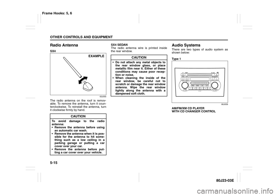
The radio antenna on the roof is remov-
able. To remove the antenna, turn it coun-
terclockwise. To reinstall the antenna, turn
it clockwise firmly by hand.SX4 SEDAN
The radio antenna wire is printed inside
the rear window.
Audio SystemsThere are two types of audio system as
shown below:
Ty p e 1
80J059
AM/FM/XM CD PLAYER
WITH CD CHANGER CONTROL
CAUTION
To avoid damage to the radio
antenna:
Remove the antenna before using
an automatic car wash.
Remove the antenna when it is pos-
sible for the antenna to hit some-
thing such as a low ceiling in a
parking garage or putting a car
cover over your car.
Remove the antenna before put-
ting a car cover over your vehicle.
EXAMPLE
CAUTION
Do not attach any metal objects to
the rear window glass, or place
metallic film near it. Either of these
conditions may cause poor recep-
tion or noise.
When cleaning the inside of the
rear window, be careful not to
scratch or damage the rear window
antenna. Wipe the rear window
lightly along the antenna with a
dampened soft cloth.
Frame Hooks: 5, 6
Page 161 of 297

5-20
OTHER CONTROLS AND EQUIPMENT
80J23-03E
Listening to the Radio
80J062
(1)
(4)(6)
(2)
(3)
(5)
(5)
(1)
(4)(6)
(2)
(3)
Type 1 AM/FM/XM CD PLAYER WITH CD CHANGER CONTROL
Type 2 AM/FM/XM 6-CD PLAYER WITH CD CHANGER CONTROL
Display
66J097
(1) Band switch button (FM/AM)
(2) Seek up button
(3) Seek down button
(4) Manual tuning knob
(5) Preset buttons (1 to 6)
(6) Auto store button (AS)/
Scan button (SCAN)
(A) Band
(B) Preset channel number
(C) Stereo indicator
(D) Frequency
(A)
(B)
(C)
(D)
Page 162 of 297
5-21OTHER CONTROLS AND EQUIPMENT
80J23-03E
Selecting the reception band
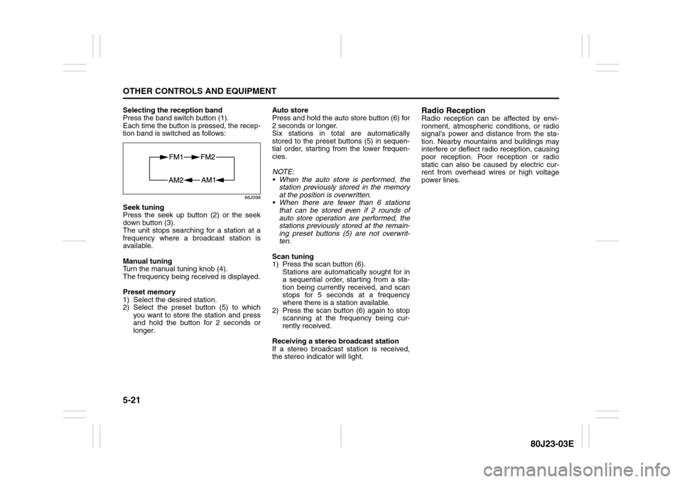
Press the band switch button (1).
Each time the button is pressed, the recep-
tion band is switched as follows:
66J098
Seek tuning
Press the seek up button (2) or the seek
down button (3).
The unit stops searching for a station at a
frequency where a broadcast station is
available.
Manual tuning
Turn the manual tuning knob (4).
The frequency being received is displayed.
Preset memory
1) Select the desired station.
2) Select the preset button (5) to which
you want to store the station and press
and hold the button for 2 seconds or
longer.Auto store
Press and hold the auto store button (6) for
2 seconds or longer.
Six stations in total are automatically
stored to the preset buttons (5) in sequen-
tial order, starting from the lower frequen-
cies.
NOTE:
When the auto store is performed, the
station previously stored in the memory
at the position is overwritten.
When there are fewer than 6 stations
that can be stored even if 2 rounds of
auto store operation are performed, the
stations previously stored at the remain-
ing preset buttons (5) are not overwrit-
ten.
Scan tuning
1) Press the scan button (6).
Stations are automatically sought for in
a sequential order, starting from a sta-
tion being currently received, and scan
stops for 5 seconds at a frequency
where there is a station available.
2) Press the scan button (6) again to stop
scanning at the frequency being cur-
rently received.
Receiving a stereo broadcast station
If a stereo broadcast station is received,
the stereo indicator will light.
Radio ReceptionRadio reception can be affected by envi-
ronment, atmospheric conditions, or radio
signal’s power and distance from the sta-
tion. Nearby mountains and buildings may
interfere or deflect radio reception, causing
poor reception. Poor reception or radio
static can also be caused by electric cur-
rent from overhead wires or high voltage
power lines.
Page 172 of 297
5-31OTHER CONTROLS AND EQUIPMENT
80J23-03E
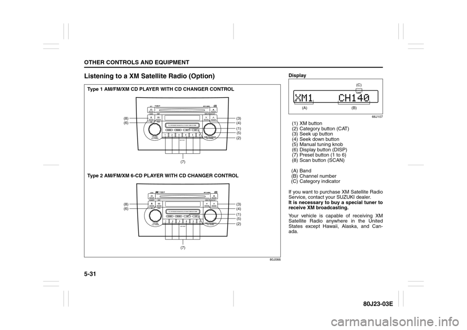
Listening to a XM Satellite Radio (Option)
80J066
(5)(2)
(8)
(6)
(3)
(4)
(7)
(1)(5)(2)
(8)
(6)
(3)
(4)
(7)
(1)
Type 1 AM/FM/XM CD PLAYER WITH CD CHANGER CONTROL
Type 2 AM/FM/XM 6-CD PLAYER WITH CD CHANGER CONTROL
Display
66J107
(1) XM button
(2) Category button (CAT)
(3) Seek up button
(4) Seek down button
(5) Manual tuning knob
(6) Display button (DISP)
(7) Preset button (1 to 6)
(8) Scan button (SCAN)
(A) Band
(B) Channel number
(C) Category indicator
If you want to purchase XM Satellite Radio
Service, contact your SUZUKI dealer.
It is necessary to buy a special tuner to
receive XM broadcasting.
Your vehicle is capable of receiving XM
Satellite Radio anywhere in the United
States except Hawaii, Alaska, and Can-
ada.
(A)
(B) (C)
Page 173 of 297
5-32
OTHER CONTROLS AND EQUIPMENT
80J23-03E
XM MODE
Selecting a band
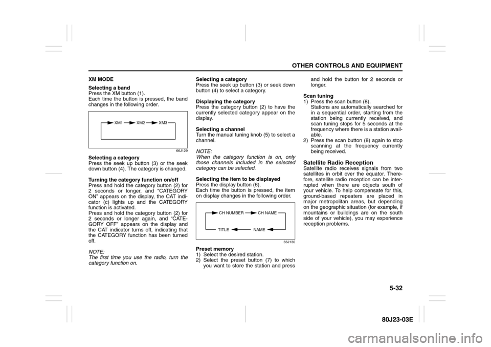
Press the XM button (1).
Each time the button is pressed, the band
changes in the following order.
66J129
Selecting a category
Press the seek up button (3) or the seek
down button (4). The category is changed.
Turning the category function on/off
Press and hold the category button (2) for
2 seconds or longer, and “CATEGORY
ON” appears on the display, the CAT indi-
cator (c) lights up and the CATEGORY
function is activated.
Press and hold the category button (2) for
2 seconds or longer again, and “CATE-
GORY OFF” appears on the display and
the CAT indicator turns off, indicating that
the CATEGORY function has been turned
off.
NOTE:
The first time you use the radio, turn the
category function on.Selecting a category
Press the seek up button (3) or seek down
button (4) to select a category.
Displaying the category
Press the category button (2) to have the
currently selected category appear on the
display.
Selecting a channel
Turn the manual tuning knob (5) to select a
channel.
NOTE:
When the category function is on, only
those channels included in the selected
category can be selected.
Selecting the item to be displayed
Press the display button (6).
Each time the button is pressed, the item
on display changes in the following order.
66J130
Preset memory
1) Select the desired station.
2) Select the preset button (7) to which
you want to store the station and pressand hold the button for 2 seconds or
longer.
Scan tuning
1) Press the scan button (8).
Stations are automatically searched for
in a sequential order, starting from the
station being currently received, and
scan tuning stops for 5 seconds at the
frequency where there is a station avail-
able.
2) Press the scan button (8) again to stop
scanning at the frequency currently
being received.
Satellite Radio ReceptionSatellite radio receives signals from two
satellites in orbit over the equator. There-
fore, satellite radio reception can be inter-
rupted when there are objects south of
your vehicle. To help compensate for this,
ground-based repeaters are placed in
major metropolitan areas, but depending
on the geographic situation (for example, if
mountains or buildings are on the south
side of your vehicle), you may experience
reception problems.
XM1 XM2
XM3
CH NUMBER CH NAME
NAME TITLE