2010 SUZUKI SX4 Meter
[x] Cancel search: MeterPage 91 of 297

2-74
BEFORE DRIVING
80J23-03E
Odometer / Illumination Control Setting
When the ignition switch is in the “ON”
position, the display (D) shows the odome-
ter.
If you turn the indicator selector knob (2)
clockwise or counterclockwise, the display
will change to the illumination control set-
ting.
Odometer
The odometer records the total distance
the vehicle has been driven.Illumination control setting
When the ignition switch is turned to the
“ON” position, the instrument panel lights
come on.
Your vehicle has a system to automatically
dim the brightness of the instrument panel
lights when the position lights or headlights
are on.
You can change the brightness of the
instrument panel lights regardless of
whether the position lights or headlights
are off or on.
To increase the brightness of the instru-
ment panel lights, turn the indicator selec-
tor knob (1) clockwise.
To reduce the brightness of the instrument
panel lights, turn the indicator selector
knob (1) counterclockwise.
80JM039
CAUTION
Keep track of your odometer reading
and check the maintenance schedule
regularly for required services.
Increased wear or damage to certain
parts can result from failure to per-
form required services at the proper
mileage intervals.
(Brightest)
(Initial setting)
(Dimmest)
Page 92 of 297

2-75BEFORE DRIVING
80J23-03E
NOTE:
If you push the indicator selector knob or
do not turn the knob for more than 5 sec-
onds while activating the illumination
control, the illumination control will be
canceled automatically and the display
(D) will show the odometer indication.
You can change the brightness when the
position lights or headlights are on even
if the ignition switch is in the “ACC” or
“LOCK” position.
When you reconnect the negative (–) ter-
minal to the battery, the brightness of the
instrument panel lights will be reinitial-
ized. Readjust the brightness according
to your preference.
NOTE:
If you select the lowest brightness level
when the position lights or headlights are
on, the instrument panel lights other than
meter lights are turned off.
Clock (if equipped)
When the ignition switch is in the “ON”
position, the display (E) shows the time.To change the time indication:
1) Push the trip meter selector knob (1)
and the indicator selector knob (2)
together.
2) To change the hour indication, turn the
indicator selector knob (2) left or right
repeatedly when the hour indication
flashes. To change the hour indication
quickly, turn and hold the indicator
selector knob (2). To set the hour indi-
cation, push the the indicator selector
knob (2) and the minute indication will
flash.
3) To change the minute indication, turn
the indicator selector knob (2) left or
right repeatedly when the minute indi-
cation flashes. To change the minute
indication quickly, turn and hold the
indicator selector knob (2). To set the
minute indication, push the indicator
selector knob (2).
NOTE:
When you reconnect the negative (–) ter-
minal to the battery, the clock indication will
be reinitialized. Change the indication
again to your preference.
Lighting Control Lever
65D611
WARNING
If you attempt to adjust the display
while driving, you could lose control
of the vehicle.
Do not attempt to adjust the display
while driving.
WARNING
If you attempt to adjust the display
while driving, you could lose control
of the vehicle.
Do not attempt to adjust the display
while driving.
WARNING
To avoid possible injury, do not oper-
ate controls by reaching through the
steering wheel.
Page 111 of 297
3-10
OPERATING YOUR VEHICLE
80J23-03E
3) Close the engine hood securely before
starting the engine.
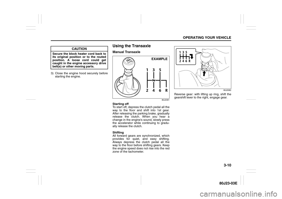
Using the TransaxleManual Transaxle
80J2081
Starting off
To start off, depress the clutch pedal all the
way to the floor and shift into 1st gear.
After releasing the parking brake, gradually
release the clutch. When you hear a
change in the engine’s sound, slowly press
the accelerator while continuing to gradu-
ally release the clutch.
Shifting
All forward gears are synchronized, which
provides for quiet, and easy shifting.
Always depress the clutch pedal all the
way to the floor before shifting gears. Keep
the engine speed does not rise into the red
zone of the tachometer.
80J2082
Reverse gear: with lifting up ring, shift the
gearshift lever to the right, engage gear.
CAUTION
Secure the block heater cord back to
its original position or to the routed
position. A loose cord could get
caught in the engine accessory drive
belt(s) or other moving parts.
EXAMPLE
Page 137 of 297
4-4
DRIVING TIPS
80J23-03E
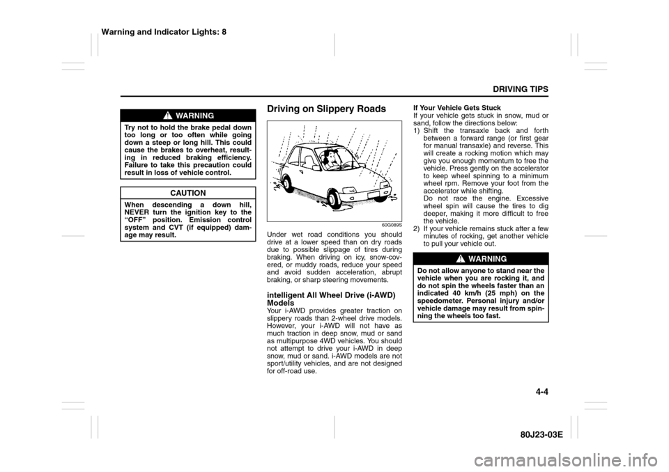
Driving on Slippery Roads
60G089S
Under wet road conditions you should
drive at a lower speed than on dry roads
due to possible slippage of tires during
braking. When driving on icy, snow-cov-
ered, or muddy roads, reduce your speed
and avoid sudden acceleration, abrupt
braking, or sharp steering movements.intelligent All Wheel Drive (i-AWD)
ModelsYour i-AWD provides greater traction on
slippery roads than 2-wheel drive models.
However, your i-AWD will not have as
much traction in deep snow, mud or sand
as multipurpose 4WD vehicles. You should
not attempt to drive your i-AWD in deep
snow, mud or sand. i-AWD models are not
sport/utility vehicles, and are not designed
for off-road use.If Your Vehicle Gets Stuck
If your vehicle gets stuck in snow, mud or
sand, follow the directions below:
1) Shift the transaxle back and forth
between a forward range (or first gear
for manual transaxle) and reverse. This
will create a rocking motion which may
give you enough momentum to free the
vehicle. Press gently on the accelerator
to keep wheel spinning to a minimum
wheel rpm. Remove your foot from the
accelerator while shifting.
Do not race the engine. Excessive
wheel spin will cause the tires to dig
deeper, making it more difficult to free
the vehicle.
2) If your vehicle remains stuck after a few
minutes of rocking, get another vehicle
to pull your vehicle out.
WARNING
Try not to hold the brake pedal down
too long or too often while going
down a steep or long hill. This could
cause the brakes to overheat, result-
ing in reduced braking efficiency.
Failure to take this precaution could
result in loss of vehicle control.
CAUTION
When descending a down hill,
NEVER turn the ignition key to the
“OFF” position. Emission control
system and CVT (if equipped) dam-
age may result.
WARNING
Do not allow anyone to stand near the
vehicle when you are rocking it, and
do not spin the wheels faster than an
indicated 40 km/h (25 mph) on the
speedometer. Personal injury and/or
vehicle damage may result from spin-
ning the wheels too fast.
Warning and Indicator Lights: 8
Page 140 of 297
4-7DRIVING TIPS
80J23-03E
MEMO
Warning and Indicator Lights: 8
A/T Selector Position Indicator: 8
Speedometer/Odometer/Trip meter: 8
Page 183 of 297
5-42
OTHER CONTROLS AND EQUIPMENT
80J23-03E
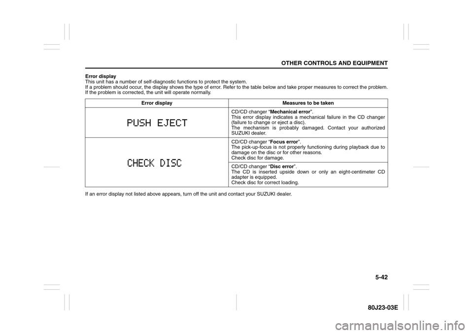
Error display
This unit has a number of self-diagnostic functions to protect the system.
If a problem should occur, the display shows the type of error. Refer to the table below and take proper measures to correct the problem.
If the problem is corrected, the unit will operate normally.
If an error display not listed above appears, turn off the unit and contact your SUZUKI dealer. Error display Measures to be taken
CD/CD changer “Mechanical error”.
This error display indicates a mechanical failure in the CD changer
(failure to change or eject a disc).
The mechanism is probably damaged. Contact your authorized
SUZUKI dealer.
CD/CD changer “Focus error”.
The pick-up-focus is not properly functioning during playback due to
damage on the disc or for other reasons.
Check disc for damage.
CD/CD changer “Disc error”.
The CD is inserted upside down or only an eight-centimeter CD
adapter is equipped.
Check disc for correct loading.
Page 207 of 297
7-2
INSPECTION AND MAINTENANCE
80J23-03E
NOTICE (for U.S.A.)
Maintenance, replacement or repair of
the emission control devices and sys-
tems may be performed by any automo-
bile repair establishment or individual
using any part which has been certified
under the provisions in the Clean Air
Act sec. 207. (a) (2).
Maintenance ScheduleThe following table shows the times when
you should perform regular maintenance
on your vehicle. This table shows in miles,
kilometers and months when you should
perform inspections, adjustments, lubrica-
tion and other services. These intervals
should be shortened if driving is usually
done under severe conditions (refer to
“Maintenance Recommended Under
Severe Driving Conditions”).
WARNING
SUZUKI recommends that mainte-
nance on items marked with an aster-
isk (*) be performed by your
authorized SUZUKI dealer or a quali-
fied service technician. If you are
qualified, you may perform mainte-
nance on the unmarked items by
referring to the instructions in this
section. If you are not sure whether
you can successfully complete any of
the unmarked maintenance jobs, ask
your authorized SUZUKI dealer to do
the maintenance for you.
CAUTION
Whenever it becomes necessary to
replace parts on your vehicle, it is
recommended that you use genuine
SUZUKI replacement parts or their
equivalent.
WARNING
The shock absorbers are filled with
high pressure gas. Never attempt to
disassemble them or throw them into
a fire. Avoid storing them near a
heater or heating device. When
scrapping the absorber, the gas must
be released from the absorber safely.
Ask your dealer for assistance.
Driving on Hills: NO
Driving on Slippery Roads: NO
Page 208 of 297

7-3INSPECTION AND MAINTENANCE
80J23-03E
Periodic Maintenance ScheduleR: Replace or change
I : Inspect, clean, adjust, lubricate or replace as necessary
#1: Be sure to perform the engine coolant level check under the daily inspection in “OPERATING YOUR VEHICLE” section.
If you replace the engine coolant other than the SUZUKI LLC: Super (Blue), follow the schedule of SUZUKI LLC: Standard (Green).Interval: This interval should be judged by
odometer reading or months, whichever comes
first.miles (x 1000) 7.5 15 22.5 30 37.5 45 52.5 60 67.5 75
km (x 1000) 12.5 25 37.5 50 62.5 75 87.5 100 112.5 125
months 7.5 15 22.5 30 37.5 45 52.5 60 67.5 75ENGINE & EMISSION CONTROL
1. Drive belt
Inspect for damage
–
–
–
I
–
–
–
I
–
–
*2.Valve lash (clearance) ––––––– I ––3.Engine oil and oil filter
R
R
R
R
R
R
R
R
R
R
*4. Cooling system hoses and connections – – – I – – – I – –5.Engine coolant
SUZUKI LLC: Standard (Green)
–
–
–
R
–
–
–
R
–
–
SUZUKI LLC: Super (Blue) (#1) First time only: Replace at 150000 km (90000 miles) or 90 months
Second time and after: Replace every 75000 km (45000 miles) or 45 months
*6. Exhaust pipes and mountings – – – I – – – I – –*7.
EVAP canister
Replace every 250000 km (150000 miles) or 180 months
*8.Emission-related hoses & tubes ––––––– I ––9.Spark plugs
–
–
–
–
–
–
–
R
–
–
*10. Ignition coil (plug cap) – – – I – – – I – –*11.
Fuel tank & cap
–
I
–
I
–
I
–
I
–
I
12. Air cleaner filter element (paved road) – – – R – – – R – –*13.
Fuel filter
–
–
–
–
–
–
–
–
–
–
*14. Fuel lines and connections – – – I – – – I – –*15.
Canister air suction filter
Replace every 250000 km (150000 miles) or 180 months
Driving on Slippery Roads: NO